1
Optimux-XLT1 Installation and Operation Manual
Chapter 5 Troubleshooting & Diagnostics
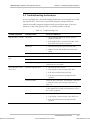
5.2 Troubleshooting Instructions
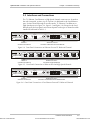
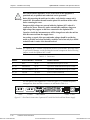
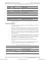
In case a problem arises, check the displayed indications and using this section and
the Optimux-XLT1 Front Panel Controls table attempt to interpret and solve.
Identify the trouble symptoms and perform the actions listed under "Corrective
Measures" in the order given in Table 5-2, until the problem is solved.
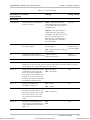
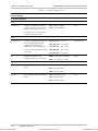
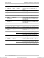
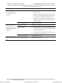
Table 5-2. Troubleshooting Chart
Trouble Symptoms
Probable Cause
Corrective Measures
Optimux-XLT1 is "dead".
No power
1. Check that both ends of the power cable are
properly connected.
2. If the Optimux-XLT1 is powered from DC, check
the polarity of the power connections.
Blown fuse
1. Disconnect the power cable from both ends
2. Replace the fuse with another fuse of the same
rating.
One of the PWR LEDs is
red.
The LINK SYNC LOSS
LED is ON
Defective Optimux-XLT1
Replace Optimux-XLT1
Power connection
Check the connection of the power cable.
Blown fuse.
Replace the fuse with another fuse of the same rating.
Defective power supply
If the PWR LED is still RED, have the Optimux-XLT1
repaired as soon as possible.
Defective Optimux-XLT1
1. Set the clock source to INT.
2. Loop the link connection with a short fiber.
3. If the LED is still ON replace the link.
4. If the LED is still ON have the Optimux-XLT1
repaired.
External problem
The LINK AIS LED is ON External problem
Order from: Cutter Networks
Defective Optimux-XLT1
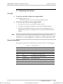
Check the link connections. Use loopback connections
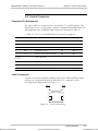
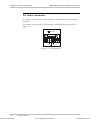
to isolate the faulty unit (see Loop Connections on
page 5-1).
The remote equipment connected to the fiber optic link
of the Optimux-XLT1 sends an AIS sequence. Check
the remote equipment.
1. Set the clock source to INT.
2. Loop the link connection with a short fiber/coax.
3. If the LED is still ON have the Optimux-XLT1
repaired.
Troubleshooting Instructions
Ph:727-398-5252/Fax:727-397-9610
5-3
www.bestdatasource.com