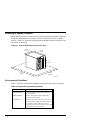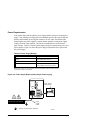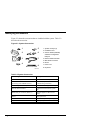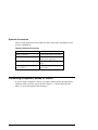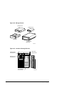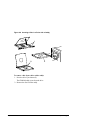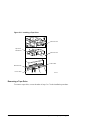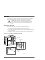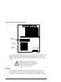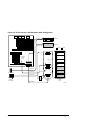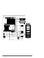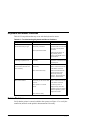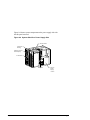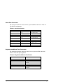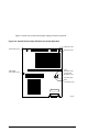
1
AlphaServer 1000A Owner's Guide Order Number: EK–ALPSV–OG. A02 Digital Equipment Corporation Maynard, Massachusetts February 1996 October 1996 Digital Equipment Corporation makes no representations that the use of its products in the manner described in this publication will not infringe on existing or future patent rights, nor do the descriptions contained in this publication imply the granting of licenses to make, use, or sell equipment or software in accordance with the description. Possession, use, or copying of the software described in this publication is authorized only pursuant to a valid written license from Digital or an authorized sublicensor. Copyright Digital Equipment Corporation, 1996. All Rights Reserved. The following are trademarks of Digital Equipment Corporation: Alpha, AlphaGeneration, DEC, DECchip, Digital, OpenVMS, OpenVMS Alpha, and the DIGITAL logo. Digital UNIX Version 3.0 is an X/Open UNIX 93 branded product. The following are third party trademarks: Microsoft is a registered trademark, and Microsoft Windows and Microsoft Windows NT are trademarks of Microsoft Corporation. OSF/1 is a trademark of the Open Software Foundation, Inc. PostScript is a trademark of Adobe Systems, Inc. All other trademarks and registered trademarks are the property of their respective holders. S3379 FCC ID: AO9-PB702 FCC NOTICE: This equipment has been tested and found to comply with the limits for a Class B digital device, pursuant to Part 15 of the FCC rules. These limits are designed to provide reasonable protection against harmful interference in a residential installation. Any changes or modifications made to this equipment may void the user's authority to operate this equipment. This equipment generates, uses, and can radiate radio frequency energy and, if not installed and used in accordance with the instructions, may cause harmful interference to radio communications. However, there is no guarantee that interference will not occur to radio or television reception. If this equipment does cause harmful interference to radio or television reception, which can be determined by turning the equipment off and on, the user is encouraged to try to correct the interference by one or more of the following measures: - Reorient or relocate the receiving antenna. - Increase the separation between the equipment and receiver. - Connect the equipment into an outlet on a circuit different from that to which the receiver is connected. - Consult the dealer or an experienced radio/TV technician for help. The user may find the following booklet prepared by the Federal Communications Commission helpful: How to Identify and Resolve Radio-TV Interference Problems. This booklet is available from the U.S. Government Printing Office, Washington, D.C., 20402. Stock No. 004-00398-5. All external cables connecting to this basic unit need to be shielded. For cables connecting to option boards, see the option manual or installation instructions. This digital apparatus does not exceed the Class B limits for radio noise emissions set out in the radio interference regulations of the Canadian Department of Communications. ACOUSTIC DECLARATION: Preliminary declared values per ISO 9296 and ISO 7779: AlphaServer 1000A (PB73A-A9/PB74A-A9) LwAd, B LpAm, dBA (Bystander Positions) Idle Operating 5.6 5.6 36 36 5.7 5.8 38 39 AlphaServer 1000A (PB73A-A9/PB74A-A9) with 6xRZ26L Idle Operating Current values for specific configurations are available from Digital representatives. 1 B = 10 dBA. Contents Preface About This Guide.............................................................................................................. xi Purpose and Audience ......................................................................................... xi Before You Use This Guide ................................................................................. xi Reader's Comment's ............................................................................................ xi Online Version.................................................................................................... xi Organization .....................................................................................................xiii Conventions.................................................................................................................... xiv Related Documentation .................................................................................................... xv 1 Overview Introduction ....................................................................................................................1-1 System Overview ............................................................................................................1-1 Supported Operating Systems............................................................................1-2 System Console Firmware .................................................................................1-2 System Features.................................................................................................1-4 Front Panel Controls and Indicators ..................................................................1-6 Rear Panel Ports and Slots.................................................................................1-9 Internal System Options ..................................................................................1-10 External Options ............................................................................................. 1-12 Ordering Options ............................................................................................1-12 2 Hardware Installation Introduction ....................................................................................................................2-1 Hardware Setup Overview...............................................................................................2-1 Selecting a System Location............................................................................................2-2 Environmental Conditions.................................................................................2-2 Power Requirements..........................................................................................2-4 Identifying Accessories ...................................................................................................2-6 Optional Accessories .........................................................................................2-7 Connecting a Keyboard, Mouse, or Printer ......................................................................2-7 Connecting a Monitor or Terminal..................................................................................2-8 AlphaServer 1000A Owner's Guide Contents • v Connecting to Network Hardware ................................................................................... 2-8 Verifying Hardware Setup............................................................................................... 2-9 Locking Your System ................................................................................................... 2-11 Recording the System Unit Key Number ......................................................... 2-12 3 Preparing to Install an Operating System Introduction.................................................................................................................... 3-1 Preparing to Install Windows NT.................................................................................... 3-2 Preparing the System ........................................................................................ 3-2 Installing Microsoft Windows NT ..................................................................... 3-7 Preparing to Install Digital UNIX ................................................................................... 3-7 Installation Preparation ..................................................................................... 3-7 Installing Digital UNIX .................................................................................... 3-8 Preparing to Install OpenVMS Alpha ............................................................................. 3-8 Preparing the System ........................................................................................ 3-8 Installing OpenVMS Alpha............................................................................. 3-10 4 Basic Operation Introduction.................................................................................................................... 4-1 Turning the System On................................................................................................... 4-1 Turning the System Off .................................................................................................. 4-3 Accessing the System from a Remote Location ............................................................... 4-4 Interpreting Startup Messages......................................................................................... 4-5 Reading the Startup Test Results ....................................................................... 4-7 Using the Consoles ......................................................................................................... 4-8 Invoking Console Mode .................................................................................... 4-8 When to Switch Consoles.................................................................................. 4-8 Switching to the Digital UNIX and OpenVMS Alpha (SRM) Console............... 4-9 Switching to the Windows NT (ARC) Console .................................................. 4-9 Windows NT (ARC) Console Menus............................................................... 4-10 Digital UNIX and OpenVMS Alpha (SRM) Console Commands .................... 4-11 SRM Console Security Features....................................................................... 4-13 Getting Help on the Windows NT (ARC) Console........................................... 4-15 Getting Help on the Digital UNIX and OpenVMS Alpha (SRM) Console ....... 4-17 Booting the Operating System....................................................................................... 4-19 Booting Windows NT...................................................................................... 4-23 Booting Digital UNIX or OpenVMS Alpha Operating Systems ....................... 4-25 Using Storage Drives .................................................................................................... 4-26 Using a Diskette Drive .................................................................................... 4-28 Using a CDROM Drive ................................................................................... 4-29 Using a StorageWorks Disk Drive................................................................... 4-32 Caring for Your System ................................................................................................ 4-32 vi • Contents AlphaServer 1000A Owner's Guide Cleaning Your System Unit.............................................................................4-32 Cleaning Your Mouse .....................................................................................4-32 Cleaning Your Keyboard .................................................................................4-33 Moving Your System.......................................................................................4-33 Packing Your System ......................................................................................4-33 Installing Your System at a New Location....................................................... 4-33 5 Installing and Removing Components Introduction ....................................................................................................................5-1 Preparing to Install or Remove Components....................................................................5-2 Required Equipment..........................................................................................5-2 Antistatic Precautions........................................................................................5-2 Top Cover and Side Panels .............................................................................................5-3 Removing the Top Cover and Side Panels .........................................................5-3 Replacing the Top Cover and Side Panels..........................................................5-5 Memory Modules ............................................................................................................5-6 Removing Memory Modules..............................................................................5-7 Installing Memory Modules...............................................................................5-8 PCI, EISA, and ISA, Option Cards ............................................................................... 5-10 Installing an Option Card................................................................................ 5-11 Removing an Option Card............................................................................... 5-13 Testing an Option Card Installation................................................................. 5-14 Configuring an Option Card............................................................................ 5-16 Network Interface Card ...................................................................................5-16 Storage Devices ............................................................................................................5-16 Identifying the Drive Bays...............................................................................5-17 Installing a Tape Drive.................................................................................... 5-18 Removing a Tape Drive...................................................................................5-19 Installing a CDROM Drive.............................................................................. 5-20 Removing a CDROM Drive.............................................................................5-20 Installing a StorageWorks Disk Drive ............................................................. 5-20 Installing a Diskette Drive............................................................................... 5-22 Removing a Diskette Drive..............................................................................5-23 Power Supply................................................................................................................5-24 CPU Card .....................................................................................................................5-27 6 Configuring Introduction ....................................................................................................................6-1 Viewing the System Configuration..................................................................................6-1 ARC Console Configuration Options.................................................................6-2 SRM Console Configuration Commands ...........................................................6-4 Memory ........................................................................................................................6-11 AlphaServer 1000A Owner's Guide Contents • vii Network Connections.................................................................................................... 6-12 Setting Network Configuration........................................................................ 6-12 Power Supply................................................................................................................ 6-12 Keyboard Type.............................................................................................................. 6-13 EISA and ISA Options.................................................................................................. 6-14 EISA Bus ........................................................................................................ 6-14 ISA Bus .......................................................................................................... 6-15 EISA Configuration Utility (ECU) .................................................................. 6-16 Configuring EISA Options.............................................................................. 6-18 Configuring ISA Options ................................................................................ 6-20 PCI Option Cards ......................................................................................................... 6-22 Storage Devices ............................................................................................................ 6-23 Determining SCSI Storage Device IDs ............................................................ 6-23 On-board SCSI Bus Configuration .................................................................. 6-25 Rules for Configuring SCSI Controller Option Cards ...................................... 6-25 SCSI Device Configurations............................................................................ 6-26 Single-Controller Configuration...................................................................... 6-28 Dual-Controller Configuration ........................................................................ 6-31 Dual-Controller, Split-Backplane Configuration.............................................. 6-34 Triple-Controller, Split-Backplane Configuration............................................ 6-37 7 Upgrading Introduction.................................................................................................................... 7-1 Planning Your Upgrade .................................................................................................. 7-1 Access from the Internet.................................................................................... 7-3 Digital Systems and Options Catalog ................................................................ 7-3 Upgrade Options............................................................................................................. 7-4 Firmware .......................................................................................................... 7-4 Updating Firmware Using the CDROM Drive................................................... 7-5 Updating Firmware Using the Network ............................................................. 7-6 Updating Firmware Using the Diskette Drive .................................................... 7-6 8 Troubleshooting Introduction.................................................................................................................... 8-1 Troubleshooting Overview .............................................................................................. 8-2 System Diagnostics......................................................................................................... 8-3 Interpreting Error Beep Codes........................................................................... 8-3 Reading the Console Event Log......................................................................... 8-4 The test Command ............................................................................................ 8-4 The kill and kill_diags Commands.................................................................... 8-7 The show_status Command............................................................................... 8-7 Power Problems .............................................................................................................. 8-8 viii • Contents AlphaServer 1000A Owner's Guide Console Problems ...........................................................................................................8-8 Boot Problems...............................................................................................................8-10 Problems Detected by the Operating System.................................................................. 8-12 Storage Problems ..........................................................................................................8-13 Option Card Problems...................................................................................................8-15 Network Problems ...........................................................................................8-15 EISA/ISA Bus Problems..................................................................................8-15 PCI Bus Problems ...........................................................................................8-16 Monitor and Terminal Problems ................................................................................... 8-17 Keyboard and Mouse Problems .....................................................................................8-19 Printer Problems ...........................................................................................................8-19 Overheating Problems...................................................................................................8-20 RAID Device Problems .................................................................................................8-20 Using the Fail-Safe Loader............................................................................................8-21 9 Quick Reference Introduction ....................................................................................................................9-1 Messages ........................................................................................................................9-1 Hardware Overview ........................................................................................................9-2 System Front View ............................................................................................9-2 System Rear View .............................................................................................9-3 System Side View..............................................................................................9-4 System Board Connectors, Chips, and Slots.......................................................9-6 Port Pinouts.......................................................................................................9-7 Indicator Lights ............................................................................................................ 9-11 System Board and CPU Card Jumper Settings............................................................... 9-12 SCSI ID Settings...........................................................................................................9-17 Single-Controller Configuration Jumper Options............................................. 9-17 Dual-Controller Configuration Jumper Options ...............................................9-18 Triple-Controller Configuration Jumper Options ............................................. 9-19 Specifications................................................................................................................9-20 System Architecture......................................................................................................9-22 Glossary of Terms Index AlphaServer 1000A Owner's Guide Contents • ix Preface About This Guide Purpose and Audience This guide describes how to set up, operate, troubleshoot, and maintain your server system. This information is intended for users, system managers, and others who perform system management tasks. Before You Use This Guide If you have not already installed the system, refer to the installation card shipped with the system and to Chapter 2, "Hardware Installation," in this guide. Some procedures in this document require that you refer to your operating system documentation. Please have your operating system documentation available for use with this guide. Reader's Comment's Digital welcomes your comments on this or any other manual. You can send your comments in the following ways: Internet electronic mail to: [email protected] Mail to: Digital Equipment Corporation Shared Engineering Services 129 Parker Street PKO3-2/A9 Maynard, MA 01754-2199 Online Version Your system shipment should include documentation on a CDROM. This CD contains an easy-to-navigate, electronic version of the information in this printed AlphaServer 1000A Owner's Guide Preface • xi user's guide, plus an additional resource guide. You can install the CDROM on any personal computer running Microsoft Windows 3.1 or later, Microsoft Windows NT 3.1, or a Windows emulator. The disk on which you install the CDROM must have approximately four megabytes of free space available. Organization This guide is organized as follows: The Preface provides an overview of this guide. Chapter 1, "Overview," provides an overview of the system features and capabilities. Chapter 2, "Hardware Installation," provides instructions for installing your system hardware. Chapter 3, "Preparing to Install an Operating System," explains how to prepare your system for installation of an operating system. Chapter 4, "Basic Operation," describes how to turn the system on and off, interpret startup messages, use console mode, boot an operating system, and use storage devices. Chapter 5, "Installing and Removing Components," explains how to install and remove internal system components and options. Chapter 6, "Configuring," describes how to configure the system. Chapter 7, "Upgrading," describes how to plan for upgrading the system with additional memory, network connections, power supply, options, and firmware. Chapter 8, "Troubleshooting," explains how to identify and solve system problems and how to perform diagnostics. Chapter 9, "Quick Reference" contains system messages, jumper settings, SCSI ID settings, specifications, and the system diagram. The Glossary defines technical terms related to the system. The Index provides a listing of main topics in this guide. xii • Preface AlphaServer 1000A Owner's Guide Conventions The following table lists the typographical conventions used in this guide. Convention Meaning Ctrl/x Ctrl/x indicates that you hold down the Ctrl key while you press another key, indicated here by x. Warning: Warnings contain information to prevent personal injury. Caution: Cautions provide information to prevent damage to equipment or software. Note: Notes provide important additional information that you may need when performing certain procedures. boot Commands that you enter are shown in this special typeface. Commands shown in lowercase letters can be entered in either uppercase or lowercase. Commands shown in uppercase letters must be entered in uppercase for the command to work. show config Console command abbreviations must be entered exactly as shown. [] In command descriptions, brackets indicate optional elements. {} In command descriptions, braces containing items separated by commas indicate mutually exclusive items. <> In console mode online help, angle brackets enclose a placeholder for which you must specify a value. italic type Italic type in console command sections indicates a variable. 1 In figures, a numbered callout labels a part of a figure. In text, the numbered callout refers to a labeled part of a corresponding figure. AlphaServer 1000A Owner's Guide Preface • xiii Related Documentation This section lists related documents that you may find helpful when operating your system or adding options. To Learn More about the System: Document Part Number Alpha Architecture Concepts (Digital UNIX) EY-N389E Alpha Architecture Concepts (OpenVMS Alpha) EY-K725E To Install the System: Document Part Number AlphaServer 1000A Basic Installation Card EK-ALPSV-IN DEC OSF/1 AXP Factory Installed Software User Information EK-SFFIS-UG OpenVMS Factory Installed Software User Information EK-A0377-UG To Install and Operate Options: Document Part Number RRD45 CDROM Disc Drive Operating Guide EK-RRDDD-IN TZK11 Tape Backup System User's Guide EK-TZK11-UG StorageWorks RAID Array 200 Subsystem Family Installation and Configuration Guide EK-SWRA2-IG To Service the System: xiv • Preface Document Part Number AlphaServer 1000A Service Guide EK-ALPSV-SV AlphaServer 1000A Illustrated Parts Breakdown EK-ALPSV-IP AlphaServer 1000A Owner's Guide 1 Overview Introduction This chapter provides an overview of your system features and capabilities. The following topics are covered: System Overview Supported Operating Systems Console Firmware System Features Front Panel Controls and Indicators Rear Panel Ports and Slots Internal System Options External Options Ordering Options System Overview This high-performance, single-processor system is intended for use as a local area network (LAN) server or commercial applications server. It is housed in a deskside enclosure, which is divided into two sides. One side contains components: the system board, CPU card, other logic modules, and fans. The other side contains up to two power supplies and a StorageWorks backplane. The system uses the DECchip 21064 and DECchip 21064A RISC microprocessors based on the Alpha architecture, and provides all the power of a 64-bit computing environment. The Alpha Privileged Architecture Library code (PALcode) supports multiple operating environments that offer a choice of applications. AlphaServer 1000A Owner's Guide Overview • 1-1 This system is intended for the following types of uses: As an applications server, running relational databases, electronic mail, communications, or other applications As a print server, providing common printing resources to PCs and other systems in a LAN As a file server, providing disk storage to PCs and other systems in a LAN As a compute server, displaying the output of applications that you run remotely on the server Supported Operating Systems This system supports the following operating systems: Microsoft Windows NT OpenVMS Alpha Digital UNIX (DEC OSF/1) While the operating system is running, it controls the system, which is in program mode. When the operating system is not running, a second mode, console mode, allows you to control system management functions, described in the next section. System Console Firmware You perform many of the tasks for managing and configuring your server system in console mode, where the system is controlled by the console subsystem, rather than the operating system. The console subsystem, located in ROM (read-only memory) on the system board, contains special software, called firmware, that interacts directly with hardware components and facilitates interaction between the system hardware and the operating system. Because the system is designed to support multiple operating systems, it offers two separate interfaces to the console subsystem. The Windows NT operating system is supported by the Advanced RISC Computing (ARC) console. The OpenVMS Alpha and Digital UNIX operating systems are supported by the Alpha System Reference Manual (SRM) console. Regardless of the operating system you use, you may need to access both consoles, depending on the particular task. Console Firmware Tasks The console firmware allows you to perform the tasks listed in Table 1-1 through either the ARC or the SRM console. The Windows NT (ARC) console firmware has 1-2 • Overview AlphaServer 1000A Owner's Guide a menu-based interface designed to facilitate hardware interaction with the Windows NT operating system. The OpenVMS Alpha and Digital UNIX (SRM) console firmware has a command line interface for hardware interaction with the Digital UNIX or OpenVMS Alpha operating systems. Table 1-1 Console Firmware Tasks You Are Using... And You Want to... Console to Use Windows NT Boot Windows NT ARC Run the EISA Configuration Utility ARC Run an adapter configuration utility ARC Update firmware ARC Switch to the SRM console ARC Run programs written to run within the ARC firmware ARC List Windows NT device names ARC Change Windows NT boot configurations and environment variables ARC Initialize the system ARC Display system configuration ARC Perform diagnostic tests SRM Boot Digital UNIX or OpenVMS Alpha SRM Update firmware SRM Switch to Windows NT console SRM Initialize the system SRM Display system configuration SRM Display system storage devices SRM Set and display environment variables specific to Digital UNIX and OpenVMS Alpha SRM Digital UNIX or OpenVMS Alpha Set and display environment variables that are common SRM to Digital UNIX, OpenVMS Alpha and Windows NT AlphaServer 1000A Owner's Guide Set console security SRM Perform diagnostic tests SRM Run the RAID Configuration Utility SRM command invokes ARC Run the EISA Configuration Utility SRM command invokes ARC Overview • 1-3 System Features The system provides a number of special features that enhance its reliability, ensure its availability, and improve its expansion capabilities, as well as facilitate hardware management and improve security. Reliability/Availability • 64-bit Alpha RISC architecture Provides significantly better performance than 32-bit architecture. • Error Correction Code (ECC) memory and CPU cache Allows recovery from most cache and memory errors. • Dual SCSI backplanes One SCSI controller for each backplane allows fully redundant disk subsystems. • Second power supply Provides redundant power as backup. • Variable fan speed Adjusts fan speed according to system temperature. • Internal sensors Monitor and detect internal system temperature, fan failure, power supply temperature. System Expansion • Flexible memory architecture Provides a 128-bit data path with ECC protection. System memory can be upgraded from 16 MB to 1 GB using memory options. • Seven PCI expansion slots, and two EISA expansion slots Accommodates industry-standard option cards such as Ethernet, FDDI, SCSI, and modems. • Integrated Fast Wide SCSI-2 controller with external SCSI-2 connector Supports tape, CDROM and hard disk drives without use of an expansion slot. • Integrated SVGA controller Supports management and configuration applications locally without use of an expansion slot. 1-4 • Overview AlphaServer 1000A Owner's Guide • Capacity for 10 internal storage devices Accommodates one StorageWorks modular storage system, which supports up to seven 3½-inch SCSI drives. The system also supports up to two 5½-inch, half-height drives (CDROM or tape), and one 3½-inch diskette drive. • External ports Two serial ports and one parallel port support external options such as a printer, modem or local terminal. • Wide-ready SCSI backplane Provides high-performance drive technology. • Hot swap disk capability Allows replacement of StorageWorks disk drives while the system continues to operate. Server Management • System diagnostics Allows local and remote diagnosis of system problems. • Hardware configuration Allows local and remote system configuration. • Unique asset management Unique system identifier in nonvolatile memory provides easy asset management. • RAM-based error log Records startup error messages. • Firmware upgrade utility Provides loading and verification of firmware versions. • Hard drive indicator lights Provide immediate status information on hard drive activity or failure. System Security • Key lock Limits access to system components. • Security loop (on rear of system unit) Allows system to be secured in place. • Interlock sensor switch Automatically turns off system power if the top cover is removed while power is on. AlphaServer 1000A Owner's Guide Overview • 1-5 Front Panel Controls and Indicators The controls and indicators on the front panel of the system unit are shown in Figure 1-1 and described in Table 1-2. Figure 1-1 shows the locations of the controls and indicators on the front panel of the system unit. Figure 1-1 Front Panel Indicators 8 9 10 11 1 Halt switch 2 Reset switch 3 On/Off indicator 7 4 On/Off switch 6 5 Operator control panel 6 Diskette drive activity indicator 5 7 Diskette drive eject button 8 CDROM volume control 9 CDROM activity indicator 4 3 2 10 CDROM eject button 1 MA00904 1-6 • Overview 11 CDROM emergency eject hole AlphaServer 1000A Owner's Guide Front Panel Controls and Indicators Description Table 1-2 describes how the front panel controls and indicators function. Table 1-2 Front Panel Controls and Indicators Control or Indicator Function Halt switch Halts an OpenVMS or Digital UNIX system, returning it to console mode control Does not affect a Windows NT system. Reset switch Reinitializes the system and performs startup tests On/Off switch Switches the system unit on and off On/Off indicator Lights when the system unit is turned on Diskette drive activity indicator Lights when the system is accessing the diskette drive Diskette drive eject button Ejects a diskette from the diskette drive CDROM volume control Adjusts headphone volume CDROM drive activity indicator Lights when the system is accessing the CDROM drive CDROM eject button Ejects disc from the CDROM drive Operator control panel display Displays startup messages AlphaServer 1000A Owner's Guide Overview • 1-7 Front Panel Switches The On/Off, reset, and halt switches are located on the left side of the front panel. They are identified by the icons shown in Figure 1-2. Figure 1-2 Front Panel Switches On/Off Switch Reset Switch Halt Switch MA00905 1-8 • Overview AlphaServer 1000A Owner's Guide Rear Panel Ports and Slots The ports and slots on the rear of the system unit are shown and described in Table 1-3. Figure 1-3 Rear Panel Ports and Slots 5 4 3 1 EISA/PCI slots 2 Parallel port 6 7 10 2 1 3 Serial port/ terminal port (COM2) 4 Mouse port 5 VGA port 8 6 Keyboard port 7 Serial port/ terminal port (COM1) 9 MA00211 8 SCSI port (8-bit, narrow) 9 Power inlet 10 Four additional SCSI ports (16bit, wide) AlphaServer 1000A Owner's Guide Overview • 1-9 Rear Panel Ports and Slots Description Table 1-3 describes the rear panel ports and slots shown in Figure 1-3. Table 1-3 Rear Panel Ports and Slots Port or Slot Used to connect.... Up to seven PCI slots Option cards for high-performance network, video, or disk controllers Up to two EISA slots Option cards for network, video, sound, or disk controllers Parallel port Parallel device such as a printer Serial port/terminal port (COM1) Console terminal or serial-line peripheral such as a modem Mouse port PS/2-compatible mouse VGA port VGA monitor Keyboard port PS/2-compatible keyboard Serial port (COM2) Serial-line peripheral such as a modem SCSI port External SCSI devices Power inlet System unit to a power outlet Four additional SCSI port knockouts External SCSI devices without using an adjacent slot Internal System Options Your system supports the following types of options: Storage options PCI and EISA/ISA options Memory options Storage Options Mass storage options are located in several compartments inside the system as shown in Figure 1-4. The system accommodates the following types of storage options: One diskette drive Two removable-media storage devices, typically, a CDROM drive, a digital audio tape (DAT) drive, or a quarter-inch cartridge (QIC) tape drive Up to seven 3½-inch StorageWorks drives 1-10 • Overview AlphaServer 1000A Owner's Guide Figure 1-4 shows the locations of the storage option compartments. Figure 1-4 Storage Option Compartments Tape Drive Compartment CDROM Drive Compartment Diskette Drive Compartment StorageWorks Drives Shelf MA00907 PCI, EISA, and ISA Options The system supports EISA, ISA, and PCI options, including those for: SCSI storage expansion Networking and Communications Graphics Memory Options You can increase your system's memory to one gigabyte by using various combinations of memory options. Adding more memory allows your system to run memory-intensive software more quickly. The system supports the following memory option sizes: 16 MB 32 MB 64 MB 128 MB 256 MB AlphaServer 1000A Owner's Guide Overview • 1-11 Memory options consist of five single in-line memory modules (SIMMs), including one ECC module: a 16-MB option consisting of 4-MB modules, a 32-MB option consisting of 8-MB modules, a 64-MB option consisting of 16-MB modules, a 128MB option consisting of 32-MB modules, and a 256-MB option consisting of 64-MB modules. External Options External options that can be added to the system include the following: Monitor or terminal Expansion boxes Printers RAID controller Uninterruptible power supply (UPS) Ordering Options The list of supported options is subject to change. Contact your sales representative for information on the current list of supported options and for information on ordering. If you are an Internet participant, you can obtain information related to the AlphaServer 1000A system through the Digital FTP archive: ftp.digital.com: /pub/DEC/Alpha/systems/as1000/docs/ For access through the Digital World-Wide Web Server: http://www.service.digital.com/alpha/server/1000.html Users of the Windows NT operating system can access the Microsoft hardware compatibility list (HCL) of officially supported devices: http://www.windowsnt.digital.com/support/hcl/hcl.htm 1-12 • Overview AlphaServer 1000A Owner's Guide 2 Hardware Installation Introduction This chapter explains how to set up and install your system hardware. The following topics are discussed: Hardware Setup Overview Selecting a System Location Identifying Accessories Connecting a Keyboard, Mouse, or Printer Connecting a Monitor or Terminal Connecting to Network Hardware Verifying Hardware Setup Locking Your System Hardware Setup Overview The steps for setting up your hardware are summarized as follows. Depending on the options you use with your system, these steps may vary. 1. Select a location for the system, giving consideration to service access, environmental conditions, and power requirements. 2. Confirm that you have all the desired accessories that ship with the system and any additional accessories you may want to add. 3. Connect the keyboard, mouse, printer, and monitor or terminal. 4. Connect to the network hardware. 5. Verify your hardware setup. AlphaServer 1000A Owner's Guide Hardware Installation • 2-1 Selecting a System Location When choosing a system location, keep in mind the optimal environmental conditions and power requirements for the system. Be sure to keep the system in an upright position. Figure 2-1 shows the system dimensions and the clearance needed to access the system for servicing. Figure 2-1 System Dimensions and Service Area 35 cm (14.1 in) 53 cm (21 in) 44 cm (17.4 in) 1m (36 in) 65 cm (26 in) MA00908 Environmental Conditions Table 2-1 lists the environmental conditions in which the system unit best operates. Table 2-1 Optimal Environmental Conditions Condition Specification Temperature range Room temperature: Between 10º C and 40º C (50º F and 104º F). Relative humidity Between 10% and 90% (20% to 80% with removable media options). Air circulation Allow a minimum clearance of 8 cm (3 inches) on all sides of the system unit to allow sufficient air circulation. Fans inside the system unit circulate the air to prevent excessive heat, which can damage the system components. 2-2 • Hardware Installation AlphaServer 1000A Owner's Guide Power Requirements Your system ships with one primary power supply and the option of a second power supply. The second power supply provides redundant power to the system. Both the primary and secondary power supplies connect to an AC outlet. An internal cable connecting the two power supplies is required when using the second power supply. Voltage selection is not required. The system is intended for use at all rated ACinput voltages. Table 2-2 lists the power supply ratings for systems using one or two power supplies. Figure 2-2 shows the power supply requirements for a system with one power supply. Table 2-2 Power Supply Ratings Specification Range Voltage 100-120/220-240 volts AC Frequency 50-60 Hz Current 8.5/4.0 amperes (one power cord) 7.5/3.5 amperes (two power cords) Note: These ratings are the maximum with a fully loaded system enclosure and do not include a monitor or terminal. Figure 2-2 Power Supply Requirements (Single Power Supply) Power Supply Cable Socket 100-120 VAC 7.5A 50-60 Hz 220-240 VAC 3.5A 50-60 Hz Power Supply Cable = Properly grounded power receptacle AlphaServer 1000A Owner's Guide MA00937 Hardware Installation • 2-3 Identifying Accessories Figure 2-3 shows the accessories that are included with the system. Table 2-2 describes the accessories. Figure 2-3 System Accessories 1 5 1 System unit keys (2) 2 Installation card 2 6 3 Owner's Guide (CDROM) and EISA Configuration Utility kit 3 7 4 External SCSI terminator 5 MMJ Serial Connector 6 Mouse 4 8 7 Power cord 8 Keyboard MA00213 Table 2-3 System Accessories Accessory Description System unit keys (2) Locks and unlocks the system unit Basic Installation card and Owner's Guide (in hardcopy and CDROM versions) Installation, operation, and troubleshooting information EISA Configuration Utility kit Runs the EISA Configuration Utility External SCSI terminator Terminates the SCSI bus at system rear MMJ serial port connector (H8571-1) Attaches Digital 423 DECconnect cables Mouse PS/2-style mouse Power cord Connects AC power to power supply Keyboard PS/2-style keyboard 2-4 • Hardware Installation AlphaServer 1000A Owner's Guide Optional Accessories Table 2-4 lists optional accessories that you may want to order, depending on your system's configuration. Table 2-4 Optional Accessories Accessory Description Monitor or terminal VGA or SVGA monitor or terminal Second power supply Provides redundant power in case primary power supply fails. Second power cord Connects AC power to second power supply Power supply interconnect cable (with Connects primary and secondary 3-pin connector) power supplies Connecting a Keyboard, Mouse, or Printer If you are using a keyboard, a mouse, or a printer, connect each to the appropriate connector at the rear of the system. Refer to Figure 1-3, "Rear Panel Ports and Slots," to verify the location of the connectors. AlphaServer 1000A Owner's Guide Hardware Installation • 2-5 Connecting a Monitor or Terminal Connect a VGA monitor, an SVGA monitor, or a terminal to your system unit, as shown in Figure 2-4. Figure 2-4 Connecting a Monitor or Terminal VGA Mouse Port Connection Keyboard Port Connection High-Performance Graphics Option Card Slot VTxxx Terminal Port (COM1)Connection MA00947 Connecting to Network Hardware Your system supports various network options. You can connect to ThinWire, AUI, or 10Base-T Ethernet networks as shown in Figure 2-5. With appropriate options, you can also connect to FDDI and token ring networks. 2-6 • Hardware Installation AlphaServer 1000A Owner's Guide Figure 2-5 Network Connections 10BASE-T Cable AUI Cable ThinWire Cable MA00938 Verifying Hardware Setup Before turning on the system, check that you have made all the proper cabling connections, as shown in Figure 2-6. Refer to the section, "Basic Operation," for information about turning on your system. Figure 2-6 External System Cabling Terminal VGA Monitor Modem VGA VTxxx Mouse Keyboard Printer Power Cable High-Performance Graphics Option MA00939 AlphaServer 1000A Owner's Guide Hardware Installation • 2-7 Locking Your System The system unit is protected by a key lock located on the front door that prevents unauthorized access to the hardware inside the unit. Turning the key to the left locks the front door. When the front door is locked, the top cover and side panels cannot be removed. Turning the key to the right unlocks the system unit and allows you access to install or remove system components. When the system unit is unlocked, push the lock to open the door. Figure 2-7 shows the system lock in the unlocked position. To remove the top cover, pull down the latch located on the front of the system above the lock, and while holding down the latch, pull the top cover off from the rear of the system. With the top cover and side panels removed, the system cannot be turned on. Figure 2-7 System Lock and Key MA00909 2-8 • Hardware Installation AlphaServer 1000A Owner's Guide Additional security is provided by a latching loop on the rear panel of the system unit that allows you to attach the system unit to a post or other fixed object. Recording the System Unit Key Number Write down the number and letter of the system unit key and record this information in a safe place in case you need to order a replacement key. Figure 2-8 shows the location of the key number on the system unit key. Figure 2-8 System Unit Key Number Location Key Number Location 00 MA00948 AlphaServer 1000A Owner's Guide Hardware Installation • 2-9 3 Preparing to Install an Operating System Introduction This chapter covers the following topics: • Preparing to Install Windows NT • Preparing to Install Digital UNIX • Preparing to Install OpenVMS Alpha These sections explain how to prepare for installing or upgrading: Windows NT Server or Workstation 3.51 or later Digital UNIX Version 3.0B or later OpenVMS Alpha Version 6.2-1H2 or later Note: If your system was shipped with pre-installed software, proceed to "Booting the Operating System" in Chapter 4 "Basic Operation," and refer to the software documentation to start up your operating system for the first time. Preparing to Install Windows NT Preparing the System 1. Before you install the Windows NT operating system, make sure that you have the following items: AlphaServer 1000A Owner's Guide Preparing to Install Operating System • 3-1 Microsoft Windows NT ARC firmware for the AlphaServer 1000A, Version 4.44 or later. The ARC firmware is a menu-driven utility to configure your system, and Version 4.44 is required to run Windows NT 3.51 or later. Microsoft Windows NT Server or Workstation 3.51 or later. The EISA Configuration Utility (ECU) diskette for Microsoft Windows NT, Version 1.8 or later. A partitioned and formatted hard disk drive installed in your system. If your drive has not yet been prepared, follow the instructions in "Hard Disk Preparation" later in this section. 2. If a Microsoft Windows NT product announcement was included with your system, read the announcement, which contains important READ FIRST information. 3. Contact the administrator of your local area network to obtain the network information you will need. This information will vary depending on the type of network hardware and software installed at your location. Setting the Operating System Type 1. Turn the system on by pressing the On/Off switch on the front of the system. (See Chapter 4, "Basic Operation.") After a short wait, the operator control panel on the front of the system displays the message "Model 4/2xx," and the screen displays initialization and testing information. Internal errors are indicated by audible "beep" codes. (See Chapter 8, "Troubleshooting.") 2. Press the Enter key. If your screen displays the ARC console Boot menu, your system has already been prepared for use with Microsoft Windows NT and you can proceed to the next section, "Updating the Firmware." If your screen displays a triple arrow (>>>) prompt instead of the ARC console Boot menu, your system has booted the SRM console. Proceed to step 3. 3. Type the following two commands at the SRM console prompt and press the Enter key after each command: set console graphics set os_type nt 4. Turn off the power to your system by pressing the On/Off switch on the front of your system. Wait at least 10 seconds, then turn the power back on. 5. The system performs several diagnostics. If you see an ECU error message, you can ignore it, because the remainder of the configuration procedure will correct any configuration errors that are displayed on the screen. 3-2 • Preparing to Install Operating System AlphaServer 1000A Owner's Guide Updating the Firmware When the ARC Boot menu is displayed, note the firmware version number at the top of the screen display. Compare this version number to the required version listed in your Windows NT documentation. If no update is required, proceed to the section, "Setting Default Environment Variables." If an update is required, follow these steps: 1. From the Boot menu, use the arrow keys to highlight the Supplementary menu, then press the Enter key. 2. Insert the Digital AlphaServer 1000A Drivers and Firmware Update diskette or CDROM for Windows NT 3.51 into the drive. 3. From the Supplementary menu, select "Install new firmware" and press the Enter key. The update process begins and the following prompt appears. Apu -> 4. Type Update and press the Enter key. 5. At the prompt, "Are you ready to program device?" type the letter y and press the Enter key. 6. If the update is successful, the screen displays the message, "ARC ROM update successful." If this message is not displayed, call your technical support representative for further assistance. 7. Turn off the power to your system by pressing the On/Off switch on the front of your system. Wait at least 10 seconds, then turn the power back on. Note: For more information on updating firmware, see "Upgrade Options" in Chapter 7, "Upgrading." Setting Default Environment Variables After updating the firmware, verify that the correct firmware version number is displayed at the top of the ARC Boot menu. Then follow these steps to set the default environment variables: 1. From the ARC Boot menu, select the Supplementary menu and press the Enter key. 2. Select "Set up the System..." and press the Enter key. 3. Select "Set default environment variables" and press the Enter key. 4. When prompted to enter the system partition location, select "SCSI hard disk" and press the Enter key. AlphaServer 1000A Owner's Guide Preparing to Install Operating System • 3-3 5. When prompted to enter SCSI bus and SCSI ID numbers, enter the SCSI bus and ID for the location for the system partition. These values are used to set an environment variable, which Windows NT uses to determine the correct drive and partition to boot from. If you are unsure about these values, simply accept the default values of 0. If these values are incorrect for your particular system (if, for example, your hard drives are on a secondary controller on SCSI bus 1), NT setup will prompt you to run the arcinst utility. The arcinst utility provides valid values to choose for setting this environment variable correctly. 6. When prompted to enter the partition number on the disk, verify that it is set to 1, and press the Enter key. If you plan to partition your hard disk, set the partition number to 2. Otherwise, enter the boot partition number corresponding to your existing disk and NT configuration. If you are unsure about your disk configuration, select "Display hardware configuration" to view a summary of your system hardware. 7. Select "Set default configuration" and choose the diskette and keyboard settings that correspond to your system. Setting the EISA Configuration 1. Insert the EISA Configuration Utility (ECU) diskette for Microsoft Windows NT into the diskette drive on your server. 2. From the Setup menu, select "Run EISA Configuration Utility from floppy" and press the Enter key. After a few moments, the EISA Configuration Utility dialog box appears. Press the Enter key. If any of the EISA option cards in your computer have not yet been identified, a Caution dialog box is displayed. You can ignore this dialog box because your option cards will be identified in the following steps. 3. Press the Enter key to display the "Steps in Configuring your Computer" dialog box. 4. Select "Step 3: View or edit details" to verify your system's configuration (optional). Note: Your system supports two EISA option slots. Your ECU display may show more than two slots, but only the first two are valid. 5. Select "Step 5: Save and Exit" and press the Enter key. At the confirmation prompt, select "Save the configuration" and press the Enter key. When a dialog 3-4 • Preparing to Install Operating System AlphaServer 1000A Owner's Guide box appears, indicating that the configuration has been saved, press the Enter key. Your system will restart with the updated information. Preparing Your Hard Disk If your first hard disk is already partitioned and formatted with either the FAT or NTFS file systems, you can omit the steps in the section "Partitioning and Formatting the First Hard Disk" and begin installation of the Microsoft Windows NT software. It is recommended that you partition and format your system's hard disk before installing Windows NT software, even if your hard disk has already been partitioned and formatted. Repartitioning and reformatting reduce the likelihood of operational problems due to conflicting versions of the operating system or disk-related problems. Note: If the first hard disk in your system currently contains any information that you need, back that information up to another medium before proceeding. Partitioning and Formatting Your Hard Disk Note: Omit these steps if you want to maintain your current partitions. 1. Insert the Microsoft Windows NT CDROM into your system's CDROM drive. 2. Turn on your system. After your system performs startup diagnostics, the screen displays the Windows NT (ARC) console Boot menu. 3. From the Boot menu, select "Run a program" and press the Enter key. A "Program to run" prompt appears. 4. Type cd: \alpha\arcinst and press the Enter key. The ARC Installation Program screen is displayed. 5. Select "Configure Partitions" and press the Enter key. The available disk partitioning options appear. 6. Select "Delete Partition" and press the Enter key. If your system has only one hard disk, press the Enter key. If your system has more than one hard disk, select the disk to be prepared, and press the Enter key. Depending on the previous disk configuration, you might be notified that no partitions exist, or you may see a list of one or more partitions. Follow the onscreen prompts to delete all partitions on the disk. AlphaServer 1000A Owner's Guide Preparing to Install Operating System • 3-5 7. Select "Create Partition" and press the Enter key. When the list of available disks appears, select the disk to be prepared and press the Enter key. You are prompted for the size of the partition. 8. Type 6 after the "Enter size" prompt, then press the Enter key. A 6-megabyte partition is created. This partition will be a file allocation table (FAT) system partition. Note that the number you enter depends on the maximum partition size. The number must equal the maximum size displayed minus 6. For example, if the largest possible value is 500, you would enter 494. 9. Press the Enter key to format the partition. Once the formatting is completed, press the Enter key again. 10. Select "Create Partition" and press the Enter key. When the list of available disks appears, select the first disk again and press the Enter key. You are prompted for the size of the partition. 11. Type the larger of the two values at the "Enter size" prompt, then press the Enter key. The partition is created. 12. Press the Enter key to format the partition. Once the formatting is completed, press the Enter key again. 13. Select "Make Existing Partition into a System Partition" and press the Enter key. A message may appear asking whether to overwrite an already defined system partition. Type y. If the message, "Boot selections already exist" is displayed, exit the ARCINST program, go to the Setup menu, choose "Manage boot selections," and delete all existing boot selections. Then return to the Boot menu to restart the ARCINST program and return to step 13 in these instructions. 14. When the list of available disks is displayed, select the same disk you just formatted and then press the Enter key. The list of available partitions is displayed. 15. Select "Partition 1" and press the Enter key. Your system is now prepared for installation of Microsoft Windows NT. 16. Select Exit and press the Enter key. Select Exit again and press the Enter key. Installing Microsoft Windows NT From the ARC Boot menu, select the Supplementary menu and press the Enter key. When the Supplementary menu appears, select "Install Windows NT from CDROM" 3-6 • Preparing to Install Operating System AlphaServer 1000A Owner's Guide and press the Enter key. At this point, installation of Windows NT begins. For further installation information, refer to your Windows NT documentation. Note: During installation, you are prompted for the location of the files for Microsoft Windows NT. Install the files into the larger of the two partitions you just created, and when prompted, format that partition with the NTFS file system. Preparing to Install Digital UNIX Installation Preparation Before installing Digital UNIX (DEC OSF/1) on your system, make sure that you have the following items: • Digital UNIX Version 3.0B, Version 3.2d, or later • SRM console firmware, Version 2.0-3 or later • EISA Configuration Utility (ECU) diskette, Version 1.8 or later, for Digital UNIX and OpenVMS Alpha. Before starting installation, be sure to review the Digital UNIX release notes ("General Installation") and the Digital UNIX installation guide for your version of the operating system. Setting the Operating System Type 1. Turn the system on. After a short wait, the operator control panel on the front of the system displays the message "Model 4/2xx," and the screen displays initialization and testing information. 2. Press the Enter key. If the screen displays a triple arrow prompt (>>>) you have booted the SRM console. Verify the value of the set bus_probe_algorithm environment variable. It should be set to "new." (See "Booting the Operating System" in Chapter 4, "Basic Operation.") Then, proceed to the next section, "Installing Digital UNIX." If the computer booted directly into the ARC Boot menu, and you did not see the >>> prompt, you must proceed to step 3 to switch to the SRM console. 3. From the ARC Boot menu, select the Supplementary menu. 4. From the Supplementary menu, select "Set up the system." AlphaServer 1000A Owner's Guide Preparing to Install Operating System • 3-7 5. From the Setup menu, select "Switch to OpenVMS or Digital UNIX console." This allows you to select your operating system console. 6. Select your operating system, then select "Enter" on the Setup menu. 7. When the system displays the message, "Power-cycle the system to implement the change," press the Reset button. These steps initiate loading of the firmware. Once the Digital UNIX and OpenVMS Alpha firmware is loaded and the system is initialized, the system displays the SRM console prompt (>>>). 8. Verify the value of the set bus_probe_algorithm environment variable. It should be set to "new." (See "Booting the Operating System" in Chapter 4, "Basic Operation.") Installing Digital UNIX To install the Digital UNIX operating system from a CDROM or to do a remote installation over a local network using Remote Installation Service (RIS), refer to your operating system documentation. Preparing to Install OpenVMS Alpha Preparing the System Before you install the OpenVMS Alpha operating system on your system, make sure that you have the following: • OpenVMS Alpha operating system, Version 6.2-1H2 or later • SRM console firmware, Version 2.0-3 or later • EISA Configuration Utility (ECU) diskette for Digital UNIX (DEC OSF/1) and OpenVMS Alpha, Version 1.8. Before beginning the installation or upgrade, prepare the required hardware and software components, as described in this section. After preparation is complete, refer to the OpenVMS Alpha Version 6.2 Upgrade and Installation Manual to install the operating system. Preparing Hardware Components To prepare the hardware components, follow these steps: 1. Be sure the hardware has been installed and checked for proper operation. 3-8 • Preparing to Install Operating System AlphaServer 1000A Owner's Guide 2. Be sure you know how to turn on and operate your system components, including the system unit, console, monitor or terminal, drives, and printer. Refer to the section, "Basic Operation" in this guide, if necessary. 3. Set up your system to record the installation procedure on either a hardcopy terminal or a printer attached to the console terminal. If you do not do this, the screen messages will be lost. You may want to record a transcript of screen messages to refer to during installation. Preparing Software Components To prepare the software components, follow these steps: 1. Be sure you have all the items listed on the bill of materials in the software distribution kit. If your distribution kit is incomplete, notify your service representative and request priority shipment of any missing items. 2. Review all cover letters and release notes. Setting the Operating System Type To set the operating system type, follow steps 1 through 7. 1. Turn the system on. After a short wait, the operator control panel on the front of the system displays the message "Model 4/2xx" and the screen displays initialization and testing information. 2. Press the Enter key. If the screen displays a triple arrow prompt (>>>), you have booted the SRM console. Verify that the bus_probe_algorithm environment variable is set to "new." (See "Booting the Operating System" in Chapter 4, "Basic Operation.") Then, proceed to the section "Installing OpenVMS Alpha". If the computer booted directly into the ARC Boot menu, and you did not see the >>> prompt, you must proceed to step 3 to switch to the SRM console. 3. From the ARC Boot menu, select the Supplementary menu. 4. From the Supplementary menu, select "Set up the system." 5. From the Setup menu, select "Switch to OpenVMS or Digital UNIX console." This allows you to select your operating system console. 6. Select your operating system, then select Enter on the Setup menu. 7. When the system displays the message, "Power-cycle the system to implement the change," press the Reset button. AlphaServer 1000A Owner's Guide Preparing to Install Operating System • 3-9 These steps initiate loading of the firmware. Once the Digital UNIX and OpenVMS Alpha firmware is loaded and the system is initialized, the system displays the SRM console prompt (>>>). 8. Verify the value of the set bus_probe_algorithm environment variable. It should be set to "new." (See "Booting the Operating System" in Chapter 4, "Basic Operation.") Required PALcode If your computer console does not have a specific minimum version of the privileged architecture library code (PALcode), you may not be able to boot your system during the installation or upgrade procedure. To ensure the correct version, follow these steps before performing an installation or upgrade: 1. At the SRM console prompt (>>>) on your running system, enter the show configuration command. The system display will indicate the PALcode version your system is using. 2. To determine whether your system is running the required or recommended version of PALcode, refer to the most recent OpenVMS Alpha operating system cover letter or release notes to check for new information that supplements the PALcode information in the OpenVMS Alpha Version 6.2 Upgrade and Installation Manual. You can also contact your service representative. 3. If the PALcode version is below the required or recommended minimum, upgrade your firmware either by following the directions in the section, "Firmware," in Upgrading, or by contacting your service representative. Installing OpenVMS Alpha Use the OpenVMS Alpha CDROM to install or upgrade the operating system, or to perform operations such as backing up the system disk. For installation information, refer to your operating system documentation. 3-10 • Preparing to Install Operating System AlphaServer 1000A Owner's Guide 4 Basic Operation Introduction This chapter explains how to start and stop your system, issue console commands, and operate other basic system functions. It includes the following topics: Turning the System On Turning the System Off Accessing the System from a Remote Location Interpreting Startup Messages Using the Consoles Booting the Operating System Using Storage Drives Caring for Your System This chapter assumes that you have set up the hardware and made all necessary connections, as described in the Hardware Installation chapter. Turning the System On Note: Your server may be equipped with pre-installed operating system software when you receive it. To turn on a system that has pre-installed operating system software, follow steps 1 through 5 below. For a system without pre-installed software, follow steps 1 through 8: 1. Connect any external options, such as monitors or terminals, or expansion boxes that house storage devices. 2. Make sure the top cover and side panels of the system unit enclosure are in place. The system will not start if the cover and side panels are not in place. AlphaServer 1000A Owner's Guide Basic Operation • 4-1 3. Plug the power cord into a wall outlet. If your system has two power supplies, plug in a power cord for each one. 4. Turn on any external options that are connected to the system. 5. Press the On/Off switch on the front of the system unit. The switch stays depressed in the "on" position. The green On/Off indicator on the front of the system will light. Figure 4-1 shows the location of the On/Off switch (1 shows the switch in the "on" position; 2 shows the switch in the "off" position). Figure 4-1 Location of the On/Off Switch On/Off Switch In ("On" Position) On/Off Switch Out ("Off" Position) MA00910 The screen on your monitor or terminal will display test codes and initialization messages. When the startup procedure is complete, the operator control panel displays the message "Model 4/2xx." The screen displays the SRM console prompt (>>>) or the ARC menu, depending on how the os_type environment variable has been set. 6. If you encounter a problem, verify that you correctly followed steps 1 through 5. Refer to Chapter 8, "Troubleshooting" for more information. If your operating system was preinstalled, proceed to the section, "Turning the System Off." 7. At this point, if your operating system was not preinstalled, you may have to perform one or all of the following tasks, depending on the startup display messages and the operating system you choose to run. Refer to the section "Booting the Operating System" in this chapter for more information on each of these tasks. 4-2 • Basic Operation AlphaServer 1000A Owner's Guide Run the EISA Configuration Utility. Check required environment variable settings. Change the way your system powers up or boots. Verify your configuration. 8. Install the operating system. (Refer first to Chapter 3, "Preparing to Install an Operating System" and then refer to your operating system documentation.) 9. Reboot the system by pressing the Reset button. 10. If you encounter a problem, verify that you correctly followed steps 1 through 8. Refer to Chapter 8, "Troubleshooting" for more information. Turning the System Off You may not need to turn the system off in order to resolve system hangs or similar problems. You can often recover from hangs or other problems by pressing the Reset switch on the operator control panel shown in Figure 1-2. Caution: Pressing the Reset switch reinitializes the system and causes you to lose the applications you are running. Within Windows NT, pressing the Ctrl, Alt, and Delete keys at once allows you to shut down the operating system and bring up the ARC firmware with no loss of data. The following list summarizes the steps for turning the system off. 1. Shut down the operating system, following the instructions in the operating system documentation. 2. Press the On/Off switch on the front of the system unit. Turning the System Off for an Extended Period If you need to turn off your system for an extended period, first turn off power as described above. Next, unplug the power cords from the power outlets. Caution: If two power supplies are present, unplug the power cord for each supply. AlphaServer 1000A Owner's Guide Basic Operation • 4-3 Accessing the System from a Remote Location If you are running the Digital UNIX or OpenVMS Alpha operating systems, you can invoke console mode from a remote device that is connected to your system through one of the serial ports on the rear of the system. The default console port is COM1. (See Figure 1-3, which shows the rear panel ports and slots.) To access the system from a remote location, follow these steps: 1. If you are running Digital UNIX or OpenVMS Alpha, shut down the operating system (refer to the operating system documentation, if necessary). When the shutdown has completed, press Return. The SRM console prompt (>>>) is displayed. Set the console to serial mode by turning the system off and then on or by using the following commands at the console prompt: >>> set console serial >>> init Note: From a remote location, you cannot reset or initialize a system running Windows NT. If the system is running Windows NT when you try to access it from a remote location, attempts to access the system will fail. 2. Connect to your system from the remote location. Note: Setting the tt_allow_login environment variable to 1 enables login to the SRM console firmware from alternative console ports. Setting it to 0 disables. If you want to run the EISA Configuration Utility (ECU) from a terminal connected to a serial line, refer to the section, "EISA Configuration Utility (ECU)" in Chapter 6 for more information. Note: The terminal must be set for 8-bit controls, the keyboard set so that the tilde (~) key sends the escape signal, and the console environment variable set to serial. 4-4 • Basic Operation AlphaServer 1000A Owner's Guide Interpreting Startup Messages After you turn the system on, the operator control panel and your monitor or terminal screen provide the following status information: The countdown and ready message on the operator control panel The system startup display on your monitor or terminal screen The Boot menu (for Windows NT systems) or the console prompt (for Digital UNIX or OpenVMS Alpha systems) on your monitor or terminal screen Audible beep codes indicate startup errors. See "Interpreting Error Beep Codes" in Chapter 8, "Troubleshooting." While the system runs the startup tests, the operator control panel on the front of the system displays a series of codes. When the startup tests are complete, the operator control panel displays the following message: Model 4/2xx During the startup sequence, the startup display scrolls on your monitor or terminal screen. The Windows NT system startup display looks similar to Example 4-1. After the startup display, the operating system determines whether your system displays a Boot menu (for the Windows NT operating system) or a console prompt (for Digital UNIX and OpenVMS Alpha operating systems). If the system does not display either a menu or a console prompt, press the Return key several times. If there is no response, refer to the "Troubleshooting" section of this guide for more information. Systems with Windows NT If you are using the Windows NT operating system, the ARC firmware displays the Windows NT Boot menu after the system startup display. The following example shows the Windows NT Boot menu. Example 4-1: Windows NT Boot Menu Alpha Firmware Version n.nn Copyright (c) 1993-1995 Microsoft Corporation Copyright (c) 1993-1995 Digital Equipment Corporation Boot menu: Boot the Windows NT operating system Boot an alternate operating system Run a program AlphaServer 1000A Owner's Guide Basic Operation • 4-5 Supplementary menu... Use the arrow keys to select, then press Enter. Systems with Digital UNIX or OpenVMS Alpha If you are using the Digital UNIX or OpenVMS Alpha operating systems, the SRM console prompt is displayed after the system startup display. The prompt looks like this: >>> To display any messages that may have scrolled by, enter the cat el command or more el command at the console prompt. Either command lists the contents of the event log file one screen at a time. The following example shows a sample startup display and the SRM console prompt for systems running Digital UNIX or OpenVMS. (The initial lines, related to copyright and patent information, remain on-screen for a few seconds only.) Example 4-2: Digital UNIX or OpenVMS Alpha SRM Startup Display BIOS Emulation V1.15a Copyright (c) 1993-1995 Digital Equipment Corporation All Rights Reserved Patent Pending initializing keyboard eb.....ea.e9.e8.e7.e6.e5.e4.e3.e2.e1.e0. Xn.n-nnnn, built on Oct 4 1996 at 14:48:51 >>> Reading the Startup Test Results The Windows NT startup test display looks similar to the following example. Test failures are indicated by an error list including errors that must be fixed before Windows NT may be booted. BIOS Emulation V1.15a Copyright (c) 1993-1995 Digital Equipment Corporation All Rights Reserved Patent Pending 4-6 • Basic Operation AlphaServer 1000A Owner's Guide Initializing firmware Initializing EISA bus 0 Initializing device drivers: NCRC810, SWXCR, QLOGIC, KZPSA...OK The Digital UNIX and OpenVMS Alpha startup test displays indicate successful tests with the word OK. If the System Passes Startup Tests If the system passes the startup tests, it either boots the selected operating system or emits audible "beep" codes and halts in console mode, depending on the system default settings. If the System Fails Startup Tests The following list summarizes the steps to follow if the system fails the startup tests. 1. Turn the system unit off, wait approximately 15 seconds, then turn it on again. 2. If the system continues to fail the startup tests, or emits audible error beep codes and halts, refer to the "Troubleshooting" section of this guide. Using the Consoles The Windows NT (ARC) console and the Digital UNIX and OpenVMS Alpha (SRM) console are used to perform different tasks. For example, ROM-based diagnostics (such as the test command) are run only from the Digital UNIX and OpenVMS Alpha console, regardless of the operating system you are running. Invoking Console Mode To perform tasks from console mode you must first invoke console mode by shutting down the operating system according to the operating system shutdown procedure described in your operating system documentation. If you are running either the Digital UNIX or OpenVMS Alpha operating system, you can also invoke console mode by pressing the Halt switch on the operator control panel. AlphaServer 1000A Owner's Guide Basic Operation • 4-7 Caution: If you are running Digital UNIX or OpenVMS Alpha operating systems, press the Halt switch only after you have shut down the operating system using the proper shutdown procedure. The Halt switch does not affect the Windows NT operating system. To invoke console mode in Windows NT, shut down the operating system following the procedure described in the operating system documentation. Turn the system off and then on or press the Reset switch. When to Switch Consoles You can perform most console-related tasks from the interface designed to interact with your operating system. However, the console interfaces are designed so that you can easily switch between them. You will need to switch between the consoles in the following instances: If you are running Digital UNIX or OpenVMS Alpha and need to run the RAID Configuration Utility (RCU) or other adapter utilities such as those for the KZPSA or Qlogic options, switch to the Windows NT (ARC) console. If you are running Windows NT and want to perform any of the following tasks, switch to the Digital UNIX and OpenVMS Alpha (SRM) console: 1. Test the system (other than self-tests at system startup) 2. Examine and verify memory locations that are recognized by the system 3. Set or change some environment variables, such as Ethernet device type and speed for Fast SCSI devices 4. Verify the versions of all firmware PALcode. Switching to the Digital UNIX and OpenVMS Alpha (SRM) Console Depending on the command you used to invoke the Windows NT (ARC) console, you may be able to switch to the Digital UNIX and OpenVMS Alpha (SRM) console by pressing the Reset switch on your system unit, or turning the system off and then back on. If you typed >>> arc or >>>runecu at the SRM console prompt, you can use this method. However, if you typed >>> set os_type nt, use the following procedure, which loads the firmware: 1. From the ARC Boot menu, select the Supplementary menu. 4-8 • Basic Operation AlphaServer 1000A Owner's Guide 2. From the Supplementary menu, select "Set up the system." 3. From the Setup menu, select "Switch to OpenVMS or Digital UNIX console" to select your operating system console. 4. Press enter on the Setup menu. 5. When the system displays the message, "Power-cycle the system to implement the change," press the Reset button. Once the Digital UNIX and OpenVMS Alpha firmware is loaded and the system is initialized, the system displays the SRM console prompt (>>>). Switching to the Windows NT (ARC) Console To switch from the Digital UNIX or OpenVMS Alpha (SRM) console to the Windows NT (ARC) console, type the following command at the console prompt: >>> set os_type nt AlphaServer 1000A Owner's Guide Basic Operation • 4-9 Then turn the system off and then back on. This procedure loads the firmware. Once the Windows NT firmware is loaded and the system is initialized, the system displays the Windows NT Boot menu. Note: If the screen display shows option device names flashing, see "Troubleshooting," later in this guide. As an alternate method, you can use the following command to switch from the SRM to the ARC console in your current session but return to the SRM console if you turn off the system: >>> arc Windows NT (ARC) Console Menus The Windows NT (ARC) console has three primary menus: the Boot menu, the Supplementary menu, and the Setup menu. Boot Menu Functions The Boot menu contains menu items that allow you to perform the following tasks: Boot the default boot selection Boot an alternative boot selection Run a program Access the Supplementary menu Supplementary Menu Functions The Supplementary menu contains items that allow you to perform the following tasks: Install new firmware Install Windows NT from a compact disc Access the Setup menu List the ARC firmware device names for the installed devices Return to the Boot menu 4-10 • Basic Operation AlphaServer 1000A Owner's Guide Setup Menu Functions The Setup menu contains menu items that allow you to perform the following tasks: Set the system time Set the default system partition Configure the system floppy drives and keyboard Manage the Windows NT (ARC) boot selections Set the system to boot automatically Run the EISA Configuration Utility Edit the system environment variables Reset the system to factory defaults Set the default operating system and system firmware Return to the Supplementary menu, with or without saving Setup menu changes Digital UNIX and OpenVMS Alpha (SRM) Console Commands There are two levels of Digital UNIX and OpenVMS Alpha (SRM) console commands: Basic Comprehensive Basic Commands Use basic commands to perform common tasks described in this guide. Table 4-1 lists each console task and provides the corresponding command and its syntax. Note: To limit the screen display to 23 lines at a time, use: Example: >>> more el. Or, use Example: >>> show config | more >>> more [filename]. >>> [command] | more AlphaServer 1000A Owner's Guide Basic Operation • 4-11 Table 4-1 Basic SRM Console Commands Task Command Syntax Boot the Windows NT (ARC) console firmware. arc arc Boot the operating system. boot boot [-flags [longword,]longword [-halt] [-filename] [boot_device] Display error logs. cat el cat el or more el Resume program execution. continue continue Invoke the EISA Configuration Utility. ecu ecu Display online help on using console commands. help help [command . . .] Initialize the system. init init Halt system tests invoked by test command. kill_diags kill_diags Display online help on using console commands. man man [command . . . ] Display status of all system processes. ps ps Set an environment variable. set set [-default] envar val Display the value of an environment variable or display configuration information. show show [envar] [{config,device,memory, pal,version}] Test the system and display results. test test Caution: Environment variables must be entered exactly as shown, not abbreviated. The system will not recognize an abbreviated form. 4-12 • Basic Operation AlphaServer 1000A Owner's Guide Comprehensive Commands Additional commands are available for system diagnosis and other complex tasks. Use of these commands requires detailed knowledge of your system. Do not use these commands without fully understanding the effect they can have on your system. To see a list of additional commands, enter help or man at the SRM console prompt. SRM Console Security Features Console security features, which restrict access to certain console commands, are intended to prevent unauthorized users from modifying system parameters or otherwise tampering with the system from the console. The SRM console supports two modes: Secure mode allows access only to specific console commands: start, continue, boot (with stored parameters), and login. User mode allows access to all SRM console commands Note: The security features work only if access to the system hardware is controlled. Be sure to keep the front panel of the system locked and the key secure. The set secure Command Use the set secure command to enable the security features without restarting the console. If the console password has already been set, access will be limited to the start, continue, boot (using the stored parameters), and login commands. For example: >>> set secure Console is secure If the password has not been set, the console will prompt you to set it. (See "The set password Command.") >>> set secure Secure not set. Please set the password. The set password Command Use the set password command to set or change the console password. If the password has already been set, the console prompts you for the new password and verification, then for the old password. AlphaServer 1000A Owner's Guide Basic Operation • 4-13 >>> set password Please enter the password: Please enter the password again: Now enter the old password: >>> Note: The password length must be between 15 and 30 alphanumeric characters. Any characters after the 30th are not stored. If the validation password does not match the one previously set, the password does not change. >>> set password Please enter the password: Please enter the password again: Validation error If the password has not been set, the console prompts you for the new password and verification. >>> set password Please enter the password: Please enter the password again: >>> The login Command Use the login command to turn off the security features and gain access to all the SRM console commands during a particular session. If a password has not been set when you enter the login command, you will be prompted to set it, but you need not do so unless you wish to. >>> login Secure not set. Please set the password: >>> When the console prompt is redisplayed, the console is no longer in secure mode. If a password has been set when you enter the login command, you must enter the password at the prompt: >>> login Please enter the password: If the password you enter matches the current password, the secure mode is turned off and all console commands can be used. You can then return to secure mode by initializing the system or entering the boot, continue, or start command. If you forget the password, you can use the login command and the Halt switch to clear the password: 4-14 • Basic Operation AlphaServer 1000A Owner's Guide 1. Check that the Halt switch is off. 2. Enter the login command. 3. When the Enter Password: prompt is displayed, press the Halt switch, then press Return. 4. Press the Halt switch off. The password is now cleared, and secure mode cannot be reinstated until you set a new password. Note: If you leave the Halt switch on after you clear the password, the system will not boot. The clear password Command The clear password command clears the environment variable, password, setting it to zero. Use this command when you want access to all the SRM console commands, but the system is in secure mode. To use clear password, you must know the current password. If you do not know the password, see "The login Command." >>> clear password Please enter the password: Password successfully cleared Getting Help on the Windows NT (ARC) Console The Windows NT (ARC) console provides general help on using the Setup menu, although it does not provide help on all the menu items contained in its menus. Table 4-2 lists the steps that you follow to display the Setup menu help screen. AlphaServer 1000A Owner's Guide Basic Operation • 4-15 Table 4-2 Windows NT (ARC) Console Help Step Action Result 1 If necessary, enter the Windows The system displays the Windows NT console by shutting down the NT console Boot menu. operating system following the procedure described in the operating system documentation. Turn the system off and then on. 2 Choose "Supplementary menu..." The system displays the Supplementary menu. 3 Choose "Set up the system..." The system displays the Setup menu. 4 Choose Help menu and press Enter. The system displays the help screen. Setup Menu Example 4-3 shows a partial Setup menu display with the help menu item selected (shown in bold). Example 4-3: Setup Menu Alpha Firmware Version n.nn Day, M-DD-YYYY 9:49:50 PM Copyright (c) 1993-1995 Microsoft Corporation Copyright (c) 1993-1995 Digital Equipment Corporation Setup menu: . . . Reset system to factory defaults Help Switch to OpenVMS or Digital UNIX console Supplementary menu, and do not save changes... Use the arrow keys to select, then press Enter. 4-16 • Basic Operation AlphaServer 1000A Owner's Guide Setup Menu Help Example 4-4 shows the Setup menu help display. Example 4-4: Setup Menu Help Display Do the following steps, in this order, to set up the system: 1. 2. 3. 4. 5. 6. Set system time. Set default environment variables. Set default configuration. Create at least one boot selection. Setup autoboot, if desired. Run the EISA configuration utility. -> An arrow next to a menu item means that something is wrong in this area of the machine, and you should select this item to fix it. "Reset system to factory defaults" does steps 2 -- 5 for a typical system. The ESCape key returns from a menu, and aborts a sequence. The firmware automatically reboots if the configuration is changed. Press any key to continue. . . Getting Help on the Digital UNIX and OpenVMS Alpha (SRM) Console To get online help, enter help at the SRM console prompt. Example 4-5 shows the help command and the resulting display. Example 4-5: The help Command >>> help NAME help FUNCTION Display information about console commands. AlphaServer 1000A Owner's Guide Basic Operation • 4-17 SYNOPSIS help [<command>...] Command synopsis conventions: <item> Implies a placeholder for user specified item. <item>... Implies an item or list of items. [] Implies optional keyword or item. {a,b,c} Implies any one of a, b, c. {a|b|c} Implies any combination of a, b, c. The following help topics are available: alloc check create edit false grep isp1020_edit man ps set host show hwrpb sleep update 4-18 • Basic Operation boot chmod date eval find_field halt kill memtest rm shell show iobq sp wc bpt break clear continue deposit dynamic examine exer fr_cmd free hd help kill_diags line mem_more net sa semaphore show show cluster show map show memory start stop x cat crash echo exit fw_cmd init ls nettest set show config show_status true AlphaServer 1000A Owner's Guide Booting the Operating System You may need to perform some of the following tasks before booting your operating system. Run the EISA Configuration Utility. Check required environment variable settings. Change the way your system powers up or boots. Verify your configuration. The remainder of this section contains more information about each of these tasks. Running the EISA Configuration Utility If you have added, removed, or moved an EISA or ISA card, you must run the EISA Configuration Utility before booting the operating system. Refer to "EISA Configuration Utility" under "EISA and ISA Options" in Chapter 6 of this guide for more information. Checking Required Environment Variable Settings If you are running the Digital UNIX or OpenVMS Alpha operating system, verify the value of the set bus_probe_algorithm environment variable. It should be set to "new." You may also want to check that settings for the following variables match your configuration. The SRM console command to reset each variable is shown in parenthesis. To see a complete list of environment variables, type show * at the SRM console prompt. Operating system (set os_type) Ethernet device type (set ew*0_mode) Speed for Fast SCSI devices (set pk*0_fast) Boot device (set bootdef_dev) Boot flags (set boot_osflags) Device names (set bus_probe_algorithm) Network protocols (set ew*0_protocols) AlphaServer 1000A Owner's Guide Basic Operation • 4-19 Changing Startup and Boot Defaults You can change the way the system starts up or boots the operating system. For example, you can set the system to autoboot or you can change the default boot device. To make these kinds of changes you need to change default values for your system's environment variables. To change default values for Windows NT systems, which boot automatically, you can prevent autoboot by selecting one of the menu options. To change default values for Digital UNIX or OpenVMS Alpha systems, see "set" in Table 4-1, "Basic SRM Console Commands." Startup and Boot Environment Variables The following environment variables affect the way the system starts up or boots: auto_action autoload countdown os_type Table 4-3 lists the boot environment variables and their values, and briefly describes their effects. Environment variables marked with an asterisk * in Table 4-3 require that you use the init command to initialize the firmware whenever you reset that particular variable. Example: >>> set os_type NT >>> init 4-20 • Basic Operation AlphaServer 1000A Owner's Guide Table 4-3 Startup and Boot Environment Variables Operating System Environment Variable Value Description Digital UNIX auto_action OpenVMS Alpha Boot Halt Restart *Specifies the system default startup action. Applies only to the Digital UNIX and OpenVMS Alpha operating systems. Digital UNIX bus_probe_ algorithm OpenVMS Alpha New *Improves bus sizing and configuration on systems running the Digital UNIX and OpenVMS operating systems. Failure to set this environment variable could result in errors. Windows NT autoload Yes or No Specifies whether the Windows NT operating system should boot. Does not affect the OpenVMS Alpha or Digital UNIX operating systems. If the value is YES, the Windows NT firmware boots the system after the COUNTDOWN time-limit expires. If the value is NO, the system halts at the Windows NT firmware Boot menu. Windows NT countdown 10 seconds (default value) Specifies the time limit within which you can stop the Windows NT operating system from booting if AUTOLOAD is set to YES. The time limit is specified in seconds. When you turn on the system or reinitialize the firmware, the system displays the seconds remaining before the operating system boots automatically. To stop the system from booting automatically, you must choose another menu item from the Boot menu. Windows NT os_type Digital UNIX OpenVMS Alpha NT UNIX VMS *Specifies the system default operating system setting. Depending on the value, the system either boots or restarts the specified operating system, or halts in the specified console. You can modify the value from either the Windows NT (ARC) console or Digital UNIX and OpenVMS (SRM) console. AlphaServer 1000A Owner's Guide Basic Operation • 4-21 Entering the Windows NT Firmware The system enters and remains in the Windows NT firmware under the following conditions: When os_type is set to NT and autoload is set to NO When autoload is set to YES and you choose another menu item on the Boot menu before the countdown time limit expires. Entering the Digital UNIX and OpenVMS Alpha Firmware The system enters and remains in the Digital UNIX and OpenVMS Alpha firmware under the following conditions: When auto_action is set to HALT and os_type is set either to OSF or VMS. When the startup tests fail, the system ignores the os_type setting and enters the Digital UNIX and OpenVMS Alpha console automatically. If the os_type setting is NT when the system fails, it returns to the Windows NT firmware when you correct the error. Verify Your Configuration Windows NT Systems To verify your Windows NT configuration, select the ARC console menu option "Display Hardware Configuration," which displays configuration information in a sequence of four displays. The first display shows system information such as memory, CPU speed, NVRAM usage, the ARC version time stamp, and the type of video detected. The second display lists the devices detected by the firmware, including the monitor, keyboard, serial ports, and devices on the SCSI bus. The third display contains PCI slot information: bus number, device number, function number, vendor ID, device ID, revision ID, interrupt vector, and device type. All PCI network cards are displayed. The fourth display contains EISA slot information: slot, device, and identifier. All EISA network cards are displayed. You can also list options recognized by your system by entering the Digital UNIX and OpenVMS Alpha commands described in the section "Viewing the System Configuration" in Chapter 6, "Configuring." To enter these commands, you must switch from the Windows NT (ARC) console to the Digital UNIX and OpenVMS Alpha (SRM) console. For information about switching to the Digital UNIX and OpenVMS Alpha (SRM) console, refer to "Switching to the Digital UNIX and OpenVMS Alpha (SRM) Console" earlier in this section. 4-22 • Basic Operation AlphaServer 1000A Owner's Guide Note: Switch back to the Windows NT (ARC) console before booting the Windows NT operating system. Digital UNIX or OpenVMS Alpha Systems Use the following SRM console commands to verify system configuration for Digital UNIX or OpenVMS systems. show config Displays the buses on the system and the devices found on those buses show device Displays the bootable devices and controllers in the system show memory Displays main memory configuration set and show Set and display environment variable setting Booting Windows NT When the system is shipped with the Microsoft Windows NT operating system, the system default settings cause the system to boot from the system disk automatically after it successfully completes the startup tests. However, the system counts down for 10 seconds after it displays the Boot menu before booting. You can stop the system from booting before this time limit expires by choosing another menu item, using the up or down arrow key. You can change these system default settings. For example, you can cause the system to halt at the Windows NT firmware Boot menu after the startup tests, or you can increase the countdown time limit. Changing Windows NT Boot Selections The Windows NT firmware uses boot selections to identify the location of the operating system files. When the system is shipped, the default boot selection identifies the system disk as the location of the operating system files. Thus, the system boots from the system disk. You can set alternative boot selections if, for example, you want to boot the operating system from a different device. AlphaServer 1000A Owner's Guide Basic Operation • 4-23 Using the Windows NT Boot Menu Example 4-6 shows the Windows NT Boot menu. Example 4-6: Windows NT Boot Menu Alpha Firmware Version n.nn Copyright (c) 1993-1995 Microsoft Corporation Copyright (c) 1993-1995 Digital Equipment Corporation Boot menu: Boot the default operating system Boot an alternate operating system Run a program Supplementary menu... Use the arrow keys to select, then press Enter. Table 4-4 lists the steps you must follow to boot Windows NT from the Boot menu. Table 4-4 Booting Windows NT from the Boot Menu Step Action Result 1 To boot the system using the default boot selection, choose "Boot Windows NT" on the Boot menu, and press Return. The system boots from the system disk, using the default boot selection -Environment Variables. 2 To boot the system using an alternative boot selection, choose "Boot an alternative operating system" on the Boot menu and press Return. The system displays a list of the alternative boot selection names. 3 Choose the alternative boot selection name that you want to boot and press Return. The system boots from the boot selection that you choose. 4-24 • Basic Operation AlphaServer 1000A Owner's Guide Windows NT Boot Selection Menu Use the Windows NT Boot selection menu to change boot selections for your system. Choose "Supplementary menu" from the Boot menu and then "Manage boot selection menu" to access the Boot selection menu. The following example shows the Windows NT Boot selection menu. Example 4-7: Windows NT Boot Selection Menu Alpha Firmware Version n.nn Copyright (c) 1993-1995 Microsoft Corporation Copyright (c) 1993-1995 Digital Equipment Corporation Boot selection menu: Add a boot selection Change a boot selection Check boot selections Delete a boot selection Dump boot selections Rearrange boot selections Setup menu... Use the arrow keys to select, then press Enter. Booting Digital UNIX or OpenVMS Alpha Operating Systems The operating system, if supplied, is installed on the system disk. For more information on pre-installed Digital UNIX software, see the Digital UNIX Factory-Installed Software user information. For more information on pre-installed OpenVMS Alpha software, see the OpenVMS Factory-Installed Software user information. AlphaServer 1000A Owner's Guide Basic Operation • 4-25 When the system is shipped with Digital UNIX or OpenVMS Alpha software installed, the system default settings cause the system to boot from the system disk automatically after it successfully completes the startup tests. You can change these settings if, for example, you want the system to halt at the console prompt (>>>) after it completes the startup tests. Digital UNIX and OpenVMS Alpha System Defaults The Digital UNIX and OpenVMS Alpha operating systems use default settings to tell the system where the operating system is located and how to boot the system. When the system is shipped, these default settings cause the system to boot from the system disk. You can set different default settings if, for example, you want to boot the operating system from a different device. See "set" in Table 4-1, "Basic SRM Console Commands." Boot Command Use the following command to boot either the Digital UNIX operating system or the OpenVMS Alpha operating system using the preinstalled default settings. >>> boot If you wish to change any default settings, see "Changing Startup and Boot Defaults" in the section, "Booting the Operating System" earlier in this chapter. Using Storage Drives Mass storage drives are devices that are used to store large amounts of data for extended periods. The system accommodates the following types of storage devices, shown in Figure 4-2: One 3½-inch diskette drive Two 5¼-inch half-height drives (CDROM or tape) Up to seven 3½-inch StorageWorks hard disk SCSI drives The drives are located in compartments inside your system, as shown in Figure 4-3. 4-26 • Basic Operation AlphaServer 1000A Owner's Guide Figure 4-2 Storage Devices CDROM Drive Diskette Drive Tape Drive StorageWorks Disk Drive MA00911 Figure 4-3 Location of Storage Devices Tape Drive Compartment CDROM Drive Compartment Diskette Drive Compartment StorageWorks Drives Shelf AlphaServer 1000A Owner's Guide MA00907 Basic Operation • 4-27 Using a Diskette Drive Diskette drives read information from removable diskettes. The diskette drive is located to the left of the removable-media mass storage compartment, below the CDROM drive. The diskette drive components are shown in Figure 4-4. To insert a diskette into a diskette drive: 1. Set the write-protect switch on the diskette to either the write-protected or writeenabled position. 2. Insert the diskette as shown in the figure. The activity indicator lights when the systems reads the diskette. Figure 4-4 Diskette Drive Components Activity Indicator Enabled Position Protected Position Eject Button Write-Protect Switch MA00940 To remove a diskette: Press the Eject button (5) on the diskette drive. 4-28 • Basic Operation AlphaServer 1000A Owner's Guide Using a CDROM Drive CDROM drives read information from removable CDROMs (read-only compact discs).Your system uses a CDROM drive that has an automatic loading/ejection feature that is functional only when power is supplied. The CDROM drive on your system may or may not use a disc caddy. Figure 4-5 shows the components of a caddyless CDROM drive. Caution: Handle a CDROM by its edges. Do not touch the surface of a CDROM. Fingerprints and dust can cause the CDROM to malfunction. Figure 4-5 CDROM Drive Components 1 CDROM XXXX XXXXX XXX X XXXX XX XX XXX 2 Drive headphone port X XXX XX XXX 3 Drive volume control XXXXX 4 Drive activity indicator MA00224 1 2 3 4 5 6 5 Drive eject button 6 Emergency eject hole To insert a caddyless disc in the drive: 1. Press the drive Eject button (5 in the figure). The CDROM drawer opens approximately one inch. 2. Gently pull the drawer out far enough so that you can insert the disc (1). 3. Insert the disc into the drawer. 4. Push the drawer back into the drive. The activity light (4 in the figure) comes on. When the activity light goes off, the drive is ready to use. To operate the drive, follow the instructions provided with your system software. AlphaServer 1000A Owner's Guide Basic Operation • 4-29 To remove a caddyless disc from the drive: 1. Press the drive Eject button (5). The CDROM drawer opens approximately one inch. 2. Gently pull the drawer out far enough so that you can remove the compact disc. 3. Remove the disc from the drawer. 4. Push the drawer back into the drive. Note: If the CDROM drawer will not open when you press the Eject button, use the following emergency procedure: Insert the end of a paper clip (no more than 2.0 mm in diameter) into the emergency eject hole (6 in Figure 4-5) and push in gently. The caddy will eject from the drive. (Do not insert the bar more than 1 inch [25 mm].) To insert a disc in a drive with a caddy: 1. Open the caddy by pressing the tabs on both sides of the caddy (1) in Figure 4-6. 2. Set a disc, printed side up, into the caddy as shown (2). 3. Be sure the system is on and the indicator light is off. Insert the caddy into the drive with the arrow forward (3), as shown. 4. Push the caddy into the drive as far as it will go. The caddy should be completely inside the drive when properly inserted. 5. Check the indicator light, which comes on when the caddy is inserted correctly. 4-30 • Basic Operation AlphaServer 1000A Owner's Guide Figure 4-6 Inserting a Disc in a Drive with a Caddy 1 2 3 4 52XXX XX XXXX X MA004 XXXXX XXX XXXXX XXXXX XX XXXXXXX XXXX XXXXX XXXXXX XXXXX XX XXXX XXXXX MA00452 To remove a disc from a drive with a caddy: 1. Press the drive Eject button (4). The CDROM caddy ejects from the drive. 2. Remove the disc from the caddy. AlphaServer 1000A Owner's Guide Basic Operation • 4-31 Using a StorageWorks Disk Drive StorageWorks disk drives are mass storage devices. They are located in a seven-bay shelf on the front right of the system unit, behind the door. When the system is turned on and during periods of activity, the StorageWorks disk drive indicator lights blink, but do not stay on. Table 4-5 explains the meaning of the indicator lights. Table 4-5 StorageWorks Disk Drive Indicator Lights Indicator Status Meaning Activity (green) Blinks Reading or writing to disk Fault (amber) On Problem exists Caring for Your System Before doing any cleaning of your system, make sure you turn off the system and disconnect any external devices. When using a moistened cloth for cleaning, do not allow any excess fluid to leak into the system, keyboard, or monitor. Wait until the system is completely dry before turning it on. Cleaning Your System Unit Clean the outside of your system periodically with a soft cloth lightly moistened with a mild detergent solution. Do not use solvents or abrasive cleaners. Cleaning Your Mouse If your mouse does not move smoothly or if the pointer jumps across the screen when you are using the mouse, the ball inside the mouse may need cleaning. To clean the ball, do the following: 1. Turn the mouse over and remove the plate on the bottom. 2. Remove the rubber ball. 3. Clean the ball and rollers with a cotton swab that has been lightly dampened with a mild detergent. 4. Replace the ball and plate. 4-32 • Basic Operation AlphaServer 1000A Owner's Guide Cleaning Your Keyboard From time to time, your keyboard keys may get dirty with use. Clean them with a clean cloth that has been lightly dampened with a mild detergent solution. Moving Your System Perform the following steps before moving or shipping the system: 1. Back up all files stored on the hard disk drive. 2. Turn off the system, the external peripherals, and the monitor or terminal. 3. Disconnect the power cord for each power supply from the wall outlet and from the back of the system unit. 4. Disconnect the monitor or terminal, keyboard, mouse, and any other cables from the back of the system unit. 5. Package the system as described in the next section, "Packing Your System." Packing Your System If you are moving the system a short distance (from one room to another in the same building), you do not need to pack it. If you are shipping the system or moving it by vehicle, pack it to avoid damage. Pack the system in the original packing material and containers. If you did not save the boxes and packing material, use a sturdy carton and padding to avoid damage. Installing Your System at a New Location After moving the system to a new location, follow the installation instructions that came with your system, and the information in Chapter 2, to unpack and install it. Ensure that the new location conforms to the recommendations provided in "Selecting a System Location" in Chapter 2, "Hardware Installation." AlphaServer 1000A Owner's Guide Basic Operation • 4-33 5 Installing and Removing Components Introduction This chapter explains how to prepare for and perform installation and removal of your system's components. You need to perform these procedures in order to upgrade your system or replace defective components. Topics covered in this chapter are listed below. Caution: Be sure to follow the appropriate antistatic precautions whenever handling internal components. Components listed in "Removing/Replacing Other Options" should be handled by qualified service personnel only. Preparing to Install or Remove Components Top and Side Panels Memory Modules EISA, ISA, and PCI Option Cards Storage Devices Power Supply CPU Card Removing/Replacing Other Options AlphaServer 1000A Owner's Guide Installing and Removing Components • 5-1 Preparing to Install or Remove Components To prepare your system for installation and removal of components, you will need to assemble the required equipment, familiarize yourself with antistatic precautions, and remove the top and side panels of the system unit. Required Equipment You need the following equipment to perform the installation and removal procedures described in the following sections. Flat-head screwdriver Phillips screwdriver Antistatic wrist strap Replacement option board kit or device kit, if necessary Antistatic Precautions When handling internal system components, use an antistatic wrist strap to avoid damaging the components. Caution: Do not disconnect the system unit power cord or unplug the power cord from the power supply socket. The power cord grounds the system unit, preventing damage to the internal components. Figure 5-1 shows how to attach the antistatic wrist strap to your wrist and to the system unit. 5-2 • Installing and Removing Components AlphaServer 1000A Owner's Guide Figure 5-1 Attaching the Antistatic Wrist Strap MA00913 Top Cover and Side Panels Depending on the components involved, you may not need to remove all panels from the system unit. The top cover and left side panel must be removed to install or remove any internal component; the right side panel, to install or remove a power supply or second SCSI controller that will connect to internal drives. Removing the Top Cover and Side Panels To remove the top cover and side panels, refer to Figure 5-2 and follow these steps: Caution: Make sure the system unit On/Off switch is in the "off" position before removing the system cover and panels. 1. Shut down the operating system following the instructions listed in the operating system documentation. 2. Set the On/Off switches on all external options connected to the system to the off position. AlphaServer 1000A Owner's Guide Installing and Removing Components • 5-3 3. Set the On/Off switch on the system unit to the off position. An interlocking sensor switch inside the system unit (see Figure 9-4) will automatically turn off the system if you remove the top cover and have not turned off the system. 4. Turn the front door lock to the right to unlock the system unit. 5. Pull down the top cover release latch on the front of the system until it catches in the down position. 6. Grasp the finger groove at the rear of the top cover and pull the top cover straight back about two inches, and lift up on the cover. 7. Pull the top of the side panel back, then up and away from the unit and pull up on the panel to remove it. (Repeat this step for the other panel.) Figure 5-2 Removing the Top Cover and Side Panels Top Cover Release Latch MA00914 5-4 • Installing and Removing Components AlphaServer 1000A Owner's Guide Replacing the Top Cover and Side Panels Follow these steps and refer to Figure 5-3 to replace the top cover and side panels of the system unit: 1. Align the guides on the top and bottom inside of the side panel with the lip of the system unit frame. 2. Tilt the side panel top towards the unit and lift the flange at the top of the panel over the system unit frame. 3. Slide the panel forward into position. (Repeat steps 1 to 3 for the other panel.) 4. Align the top cover with the top of the side panels and slide the cover gently onto the unit from the rear. Hold down the top cover release latch until the top cover is in place, and then release it to secure the cover and panels. 5. Lock the top cover and side panels using the system unit key. 6. Set the On/Off switches on all external options connected to the system to the "on" position. 7. Set the On/Off switch on the system unit to the "on" position. Figure 5-3 Replacing the Top Cover and Side Panels Top Cover Top Cover Release Latch Right Side Panel Top Side Panel Guide Bottom Side Panel Guide AlphaServer 1000A Owner's Guide MA00915 Installing and Removing Components • 5-5 Memory Modules The system unit supports 20 single in-line memory module (SIMM) connectors on the system board. The SIMM connectors are grouped in four memory banks consisting of five memory modules, including one for ECC (Error Correction Code). Figure 5-4 shows the four memory banks and their memory module connectors. Keep in mind the following rules when installing memory modules: A memory option consists of five memory modules. Bank 0 must contain a memory option (five modules: 0,1,2,3 plus one ECC module) All memory modules within a bank must be of the same capacity. The system unit supports five sizes of memory options: 16, 32, 64, 128, and 256 megabytes. Using combinations of these five memory options, the system supports between 16 megabytes to one gigabyte of memory. Figure 5-4 Memory Banks and Connectors Bank 3 Bank 2 Bank 1 Bank 0 ECC Banks SIMM 1 SIMM 3 SIMM 0 SIMM 2 SIMM 1 SIMM 3 SIMM 0 SIMM 2 SIMM 1 SIMM 3 SIMM 0 SIMM 2 SIMM 1 SIMM 3 SIMM 0 SIMM 2 ECC SIMM for Bank 2 ECC SIMM for Bank 3 ECC SIMM for Bank 0 ECC SIMM for Bank 1 MA00327 5-6 • Installing and Removing Components AlphaServer 1000A Owner's Guide Removing Memory Modules Caution: To avoid electrostatic damage to components, use an antistatic wrist strap while handling these components (see the section, "Antistatic Precautions"). You may need to remove memory modules to either remove or install another memory module. Note the position of any memory modules that you remove. Figure 5-5 shows the removal procedure for a memory module. To remove a memory module: 1. Remove the appropriate memory modules by pressing the metal clips (1) on both sides of the memory module connector to the side. 2. Tilt the memory module and lift it (2) out of its connector. Note: Memory modules can only be removed and installed in successive order. For example, to remove a module at bank 0, you must first remove modules 0 and 1 for banks 3, 2, and 1. AlphaServer 1000A Owner's Guide Installing and Removing Components • 5-7 Figure 5-5 Removing a Memory Module MA00233 1 2 Installing Memory Modules You need to install a new memory module to replace a faulty module or when upgrading a memory bank. You may need to remove memory modules in order to access the memory slots for any new modules (see the earlier section, "Removing Memory Modules"). To install a memory module, refer to Figure 5-6 and follow these steps: 1. Tilt the connecting end of the module and press gently on the module so it slips over the two posts located at each end of the slot (see Figure 5-5). 2. Reinstall any memory modules you may have removed for access purposes. 3. Replace the system covers following the procedures listed in "Replacing the System Unit Covers." 4. Test the memory configuration using the following commands: >>> show memory >>> memory For more information, see the section, "Configuring Memory" in Chapter 6, "Configuring." 5-8 • Installing and Removing Components AlphaServer 1000A Owner's Guide Figure 5-6 Installing a Memory Module 1 MA00234 2 AlphaServer 1000A Owner's Guide Installing and Removing Components • 5-9 PCI, EISA, and ISA, Option Cards For a description of available system options, see the section, "Upgrade Options," in Chapter 7, "Upgrading." Installing and removing PCI, EISA, and ISA, option cards includes these tasks: Installing an Option Card Removing an Option Card Testing an Option Card Installation Configuring an Option Card Figure 5-7 shows the option card slots on the system board. Figure 5-7 PCI, EISA, and ISA Slots on the System Board EISA/ISA Option Slots PCI Primary Slots 11 12 13 PCI Secondary Slots 1 2 3 4 MA00916 5-10 • Installing and Removing Components AlphaServer 1000A Owner's Guide Installing an Option Card To install a PCI, EISA, or ISA option card on the system board, refer to Figures 5-8 and 5-9, and follow the steps below. Note: If you want to install a high-performance graphics option card, you must disable the SVGA jumper (J27) on the system board. Figure 9-6 in Chapter 9, "Quick Reference" shows the jumper location. If you are running the Digital UNIX or OpenVMS Alpha operating system, run the EISA Configuration Utility (ECU) and disable the on-board VGA using the "View or Edit Details" ECU option. See "Configuring EISA Options" in Chapter 4, "Basic Operations." Caution: Static electricity can damage electronic components. Use an antistatic wrist strap while handling these components. (See "Antistatic Precautions.") 1. Select a vacant option card slot on the system board. The top two slots are reserved for EISA or ISA options; the bottom seven are for PCI options. Figure 5-8 shows examples of the three kinds of option cards. AlphaServer 1000A Owner's Guide Installing and Removing Components • 5-11 Figure 5-8 PCI, EISA, and ISA Option Cards ISA EISA MA00236 PCI 2. Remove the screw securing the slot cover to the chassis. 3. Remove the slot cover from the system unit and store it for future use. 4. Carefully install the option card into the appropriate connectors on the system board and press it firmly into place. 5. Secure the option card to the chassis using the screw you removed. 6. If you have finished removing or installing internal options, reassemble the system following the procedure described in "Replacing the Top Cover and Side Panels" earlier in this chapter. 7. Test the option card installation (see the section, "Testing an Option Card Installation" later in this chapter). 5-12 • Installing and Removing Components AlphaServer 1000A Owner's Guide Figure 5-9 Installing or Removing an Option Card Slot Cover Screw Option Card MA00917 Removing an Option Card To remove an EISA, ISA, or PCI option card from the system unit, refer to Figure 59 and follow the steps below. Caution: Static electricity can damage electronic components. Use an antistatic wrist strap while handling these components. 1. Disconnect any cables connected to the external or internal ports on the option card you want to remove. 2. Remove the slot cover screw securing the option card to the chassis. 3. Carefully disconnect the option card (1) from the slot connectors on the system board and remove it from the system. 4. If you intend leaving the option slot vacant, install a slot cover and secure it to the chassis using the screw that you removed. 5. If you have finished removing or installing internal options, reassemble the system following the procedure described in "Replacing the Top Cover and Side Panels," earlier in this chapter. AlphaServer 1000A Owner's Guide Installing and Removing Components • 5-13 Testing an Option Card Installation To test an option card installation, follow the steps in Table 5-1 and refer to Example 5-1. Caution: Reassemble the system following the procedures listed in "Replacing the Top Cover and Side Panels." Table 5-1 Testing with the show config Display Step Action Result 1 Enter the show config command to display the system configuration. The system responds with a display similar to that shown in Example 5-1. 2 Examine the PCI Bus or EISA bus information in the display to make sure that the new option is listed. If the option is not listed, see "Troubleshooting." 3 Determine the device name of the new option. You must know the device name to run diagnostic tests on the option. Enter the show device command to see the device name. 4 Run a self-test on the option by entering the test command followed by its device name. If the self-test passes, the system displays the word OK (6) before displaying the console prompt (>>>). If the system displays a failure message, see "Troubleshooting." 5-14 • Installing and Removing Components AlphaServer 1000A Owner's Guide Example 5-1 The show config Command Display >>> show config Firmware SRM Console: X4.4-5365 ARC Console: 4.43p PALcode: VMS PALcode X5.48-115, OSF PALcode X1.35-84 Serial ROM: X2.1 Processor DECchip (tm) 21064A-6 266 MEMORY 32 Meg of System Memory Bank 0 = 32 Mbytes (8 MB Per Simm) Starting at 0x00000000 PCI Bus Bus 00 Bus 00 Slot 07: Intel 8275EB PCI to Eisa Bridge Slot 08: Digital PCI to PCI Bridge Chip Bus 02 Slot 00: ISP1020 Scsi Controller pka0.7.0.2000.0 Scsi Bus ID 7 dka0.0.0.2000.0 RZ29B dka400.4.0.2000.0 RRD45 Bus 02 Slot 04: DECchip 21040 Network Controller ewa0.0.0.2004.0 08-00-2B-E5-6A-41 Bus 00 Slot 11: DECchip 21040 Network Controller ewb0.0.0.11.0 08-00-2B-E1-03-19 EISA Bus Modules (installed) >>> AlphaServer 1000A Owner's Guide Installing and Removing Components • 5-15 Configuring an Option Card Depending on the type of option card you install, you may or may not need to configure it. When installing EISA and ISA option cards, refer to the system startup display screen to see if configuration of the card is required. After you turn on the system, the system startup sequence examines the EISA option slots and reports whether you need to run the EISA Configuration Utility. See the section, "EISA and ISA Options" in Chapter 6, "Configuring" for more information. When installing PCI option cards, you do not normally need to perform any configuration procedures. The system configures PCI cards automatically. But because some PCI option modules require configuration utility diskettes, refer to the option documentation. Network Interface Card The system supports PCI or EISA network option cards. For information on installing network option cards in your system, refer to the section, "Installing an Option Card" earlier in this chapter. For information on cabling them to destinations outside the unit, refer to the documentation that accompanies the option. Storage Devices The system unit is designed to accommodate multiple SCSI devices, including a CDROM drive, a tape drive, and several StorageWorks device options. The diskette drive connects directly to the system board and is not a SCSI device. Whenever you install a SCSI device, you must assign it a unique SCSI ID number. Otherwise, the system will not recognize the device. Depending on how many SCSI devices you are using or how you want them configured, you may need to alter the SCSI cabling to enable all of the devices (see Chapter 6, "Configuring"). 5-16 • Installing and Removing Components AlphaServer 1000A Owner's Guide Identifying the Drive Bays The system contains four storage drive bays, shown in Figure 5-10. Figure 5-10 System Drive Bays 5 1/4-Inch CSI CDROM Drive Bay 5 1/4-Inch SCSI Tape Drive Bay 3 1/2-Inch Diskette Drive Bay 3 1/2-Inch StorageWorks Drive Shelf AlphaServer 1000A Owner's Guide MA00941 Installing and Removing Components • 5-17 Installing a Tape Drive To install or replace a tape drive, refer to Figure 5-11 and follow these steps: 1. If you have not done so already, remove the original drive that you want to replace. To remove the tape drive, reverse the order of steps 3 to 7 in this installation procedure. 2. If you are replacing a drive, set the SCSI ID jumpers on the replacement drive to the same ID as the original drive. If you are installing a drive, set the SCSI device ID to 5. The ID 5 is the default device ID for a tape drive. See the section, "Determining SCSI Storage Device IDs" in Chapter 6, "Configuring" for more information. 3. Remove the tape drive bracket from the bay by loosening the bracket retaining screw and pulling back on the bracket. 4. Slide the tape drive you want to install into the bracket and insert two screws on each side. 5. Slide the drive assembly into the back of the bay until its screw holes are aligned with the tape drive bracket holes. 6. Tighten the single retaining screw in the tape drive bracket. 7. Connect the power cable and the data cable to the back of the drive. 5-18 • Installing and Removing Components AlphaServer 1000A Owner's Guide Figure 5-11 Installing a Tape Drive Bracket Screw Tape Drive and Bracket Bracket Screw Data Cable Bracket Screw Power Cable MA00942 Removing a Tape Drive To remove a tape drive, reverse the order of steps 3 to 7 in the installation procedure. AlphaServer 1000A Owner's Guide Installing and Removing Components • 5-19 Installing a CDROM Drive To install or replace a CDROM drive, refer to Figure 5-12 and follow these steps: 1. Before you can install the CDROM drive, you must first remove the tape drive and tape drive bracket. See "Removing a Tape Drive" earlier in this section. 2. If you have not done so already, remove the drive you want to replace. 3. Set the SCSI ID on the replacement drive to the same ID as the original drive. If you are installing a drive, set the SCSI drive ID to 4. The ID 4 is the default device ID for a CDROM drive. See the section "Determining SCSI Storage Device IDs" in Chapter 6, "Configuring" for more information. 4. Slide the drive into the front of the bay until its screw holes are aligned with the drive bracket holes. 5. Insert two screws into each side of the CDROM drive. 6. Connect the power cable and the data cable to the back of the drive. 7. If necessary, reinstall the tape drive. See "Installing a Tape Drive" earlier in this section. 8. Screw in the holding clip that secures the drives from on top. Removing a CDROM Drive Reverse the order of steps 4 to 8 in the installation procedure to remove the CDROM drive. Installing a StorageWorks Disk Drive If your StorageWorks disk drives are plugged into a RAID controller, you can hot swap drives, that is, you can install or replace drives without first shutting down the operating system or turning off the system hardware. For more information, see the StorageWorks RAID Array 200 Subsystem Family Installation and Configuration Guide (EK-SWRA2-IG). 5-20 • Installing and Removing Components AlphaServer 1000A Owner's Guide Figure 5-12 Installing a CDROM Drive Drive Bracket Screws Data Cable Power Cable MA00918 To install a StorageWorks drive, refer to Figure 5-13 and follow these steps: 1. If your StorageWorks drives are plugged into a RAID controller, go to step 2. If your drives are not plugged into a RAID controller, shut down the operating system before you go to step 2. 2. Remove a blank bezel or drive by pressing the two mounting tabs and pull the unit out of the shelf. AlphaServer 1000A Owner's Guide Installing and Removing Components • 5-21 3. Insert the hard disk drive into the guide slots and push the drive in until its tabs lock in place. 4. Check the configuration of the drive. See the section "Determining SCSI Storage Device IDs" in Chapter 6, "Configuring" for more information. Figure 5-13 Installing a StorageWorks Disk Drive MA00240 Removing a StorageWorks Disk Drive To remove StorageWorks disk drives, reverse all steps in the installation procedure. Installing a Diskette Drive To replace a 3½-inch diskette drive, refer to Figure 5-14 and follow these steps: 1. Remove the original diskette drive. 2. Locate the ID select switch toward the rear on the righthand side of the replacement diskette drive. Set the switch to the 1 position. 3. Slide the diskette assembly into the front of the bay until the screw holes line up with the holes on the bracket. 4. Attach the mounting bracket to the replacement diskette drive using the two screws that you removed from the original diskette drive. 5. Connect the power cable and the data cable to the diskette drive. 5-22 • Installing and Removing Components AlphaServer 1000A Owner's Guide Removing a Diskette Drive To remove the diskette drive, reverse steps 3 to 5 in the installation procedure, and refer to Figure 5-14. Figure 5-14 Replacing or Installing a Diskette Drive Diskette Drive Power Cable Data Cable Screws (2) AlphaServer 1000A Owner's Guide MA00943 Installing and Removing Components • 5-23 Power Supply The following procedures describe how to install and remove the primary and optional power supplies. The primary power supply resides in the bottom position, the secondary power supply in the top position. The procedures for installing and removing both power supplies are similar, unless otherwise noted. Installing the Power Supply To install a power supply, refer to Figure 5-15, and follow these steps: 1. If you are installing a second power supply, remove the four screws that secure the protective shield at the back of the system unit. Remove the shield and store it with the screws for future use. 2. Slide the power supply over its tabs and toward the back panel so that it aligns with the screw holes in the system unit frame. The primary power supply slides directly into the lower position from the side of the system unit. The secondary power supply slides down from above the system unit and rests upon a ledge. 3. Tighten the two screws that secure the internal end of the power supply. 4. Tighten the four screws that secure the power supply to the outside of the unit. Do not use the screws that secured the protective shield. 5. Connect all internal and external cables to the power supply. If you are installing a second power supply, an additional internal cable is required for connecting the two supplies. Each power supply connects directly to an AC outlet. 5-24 • Installing and Removing Components AlphaServer 1000A Owner's Guide Figure 5-15 Installing the Power Supply Connecting Cable Cable Connections Internal Second Power Supply Position for Second Power Supply Rear Screws 6/32 Inch (4) Internal Screws 3.5 mm (2) MA00919 AlphaServer 1000A Owner's Guide Installing and Removing Components • 5-25 Removing the Power Supply To remove a power supply, refer to Figure 5-16 and follow these steps: 1. If an optional power supply is installed, you must remove it before removing the primary power supply. 2. Disconnect all internal and external cables from the power supply. 3. Loosen the four screws that secure the power supply to the outside rear of the unit. 4. Loosen the two screws that secure the internal end of the power supply to the system unit. 5. Slide the power supply towards the internal side and lift it up off its tabs. Figure 5-16 Removing the Power Supply Power Supply Rear Screws 6/32 Inch (4) Cable Connections Internal Screws 3.5 mm (2) MA00920 5-26 • Installing and Removing Components AlphaServer 1000A Owner's Guide CPU Card Your system comes with the CPU installed on a board that connects to the system board. To upgrade to another CPU type, you need to replace the CPU card. Warning: CPU and memory modules have hot components. Wait 2 minutes after power is off before handling these modules. Take appropriate antistatic precautions when handling internal parts. Removing the CPU Card To remove the CPU card, refer to Figure 5-17 and follow these steps: 1. Unscrew the crossbar that secures the outer edge of the CPU card. 2. Lift up on the other end of the bar. Release the card by extending the handle clip on each end outward. 3. Holding the outer edge of the card, gently pull it out of its system board slot. Figure 5-17 Removing and Installing the CPU Card CPU Card Handle Clip Crossbar Retaining Screw MA00944 AlphaServer 1000A Owner's Guide Installing and Removing Components • 5-27 Installing the CPU Card To install the CPU card, refer to Figure 5-17 and follow these steps: 1. Slide the card into its designated slot on the system board making sure it slips entirely into the slot. 2. Press inward on the handle clip on each end of the card until they catch in a closed position. 3. Place the crossbar in position and screw in the single retaining screw. Removing/Replacing Other Options The following components should be installed by a qualified service representative only: System board System backplane System fans Interlocking sensor switch Front bezel Operator control panel For assistance in removing or installing these components, contact your authorized service representative. 5-28 • Installing and Removing Components AlphaServer 1000A Owner's Guide 6 Configuring Introduction This chapter covers the following topics: Viewing the System Configuration Memory Network Connections Power Supply Keyboard Type EISA and ISA Option Cards PCI Option Cards Storage Devices Viewing the System Configuration Several SRM console commands or ARC console menu options allow you to examine your system configuration and environment variable settings. To use these commands or menu options, you need to invoke console mode. For information about invoking console mode, refer to the section, "Using the Consoles," in Chapter 4, "Basic Operation." AlphaServer 1000A Owner's Guide Configuring • 6-1 ARC Console Configuration Options On systems running the Windows NT operating system, the following Windows NT (ARC) menu options are used to verify system configuration: "Display Hardware Configuration" Displays system information, devices detected by the firmware, and PCI and EISA slot information. "Set Default Variables" Allows you to select values for Windows NT firmware environment variables. A sample of the "Display Hardware Configuration" display is shown in Example 6-1. Example 6-1 3/12/1996 Tuesday 9:06:23 AM Alpha Processor and System Information: Processor ID 21064 Processor Revision 3 System Revision 0x1 Processor Speed 266.02 MHz Physical Memory 64 MB Backup Cache Size 2 MB Extended Firmware Information: Version: 4.45 (Proto) 951212.0949 NVRAM Environment Usage: 75% (744 of 1024 bytes) Video Option detected: BIOS controlled video card Press any key to continue... 6-2 • Configuring AlphaServer 1000A Owner's Guide 3/12/1996 Tuesday 9:06:23 AM Devices detected by the firmware: eisa(0)video(0)monitor(0) multi(0)key(0)keyboard(0) eisa(0)disk(0)fdisk(0) multi(0)serial(0) multi(0)serial(1) scsi(0)disk(0)rdisk(0) scsi(0)cdrom(4)fdisk(0) (Removable) (4 Partitions) (Removable) DEC DEC RZ29B RRD45 (C)DEC007 (C)DEC 1084 Press any key to continue... 3/12/1996 Tuesday 9:06:23 AM PCI slot information: Bus Number 0 Device Number 7 Function Number 0 Vendor ID 8986 Device ID 482 Revision ID 4 Interrupt Vector 0 0 8 0 1011 1 2 0 0 1 11 1 0 0 1011 1000 2 1 23 1 0 19 Device Type EISA bridge PCI bridge Ethernet SCSI Press any key to continue... 3/12/1996 Tuesday 9:06:23 AM EISA slot information: Slot 0 0 Device Other Disk AlphaServer 1000A Owner's Guide Identifier DEC5000 FLOPPY Configuring • 6-3 Note: You can also list options recognized by your system by entering the Digital UNIX and OpenVMS Alpha commands described in the next section "SRM Console Configuration Commands." To enter these commands, you must switch from the Windows NT (ARC) console to the Digital UNIX and OpenVMS Alpha (SRM) console. For information about switching to the Digital UNIX and OpenVMS Alpha (SRM) console, refer to "Switching to the Digital UNIX and OpenVMS Alpha (SRM) Console" in Chapter 4, "Basic Operation." Remember to switch back to the Windows NT (ARC) console before booting the Windows NT operating system. SRM Console Configuration Commands The following console commands are used to verify system configuration on systems running either the Digital UNIX or OpenVMS Alpha operating system: show config Displays the buses on the system and the devices found on those buses. show device Displays the bootable devices and controllers in the system. show memory Displays main memory configuration. set and show Set and display environment variables. The show config Command The show config command displays all devices found on the system bus, PCI bus, and EISA bus. You can use the information in the display to identify target devices for commands such as boot and test, as well as to verify that the system sees all the devices that are installed. A sample display is shown in Example 6-2, along with an explanation of the device name convention. Figure 6-1 shows the system board connectors and slots. The configuration display includes the following information: 6-4 • Configuring AlphaServer 1000A Owner's Guide 1. Version numbers for the firmware code, PALcode, SROM chip, and CPU; CPU speed 2. Memory size and configuration for each bank of memory 3. PCI bus information: Bus 0, Slot 7 = PCI to EISA bridge chip Bus 0, Slot 8 = PCI to PCI bridge chip Bus 2, Slot 0 = SCSI controller on backplane, along with storage drives on the bus. Bus 2, Slots 1-4 = Correspond to physical PCI option module slots on the secondary PCI bus: Slot 1 = PCI1 Slot 2 = PCI2 Slot 3 = PCI3 Slot 4 = PCI4 In the case of storage controllers, the attached devices are also displayed. Bus 0, Slots 11-13 - Correspond to physical PCI option module slots on the primary PCI bus: Slot 11 = PCI11 Slot 12 = PCI12 Slot 13 = PCI13 In the case of storage controllers, the attached devices are also displayed. 4. EISA bus information: Slot numbers correspond to EISA option module slots (1 and 2). For storage controllers, the attached devices are also displayed. AlphaServer 1000A Owner's Guide Configuring • 6-5 Example 6-2: The show config Command Display >>> show config Firmware SRM Console: ARC Console: PALcode: Serial ROM: X4.4-5365 4.43p VMS PALcode X5.48-115, OSF PALcode X1.35-84 X2.1 Processor DECchip (tm) 21064A-6 266 MEMORY 32 Meg of System Memory Bank 0 = 32 Mbytes (8 MB Per Simm) Starting at 0x00000000 PCI Bus Bus 00 Bus 00 Slot 07: Intel 8275EB PCI to Eisa Bridge Slot 08: Digital PCI to PCI Bridge Chip Bus 02 Slot 00: ISP1020 Scsi Controller pka0.7.0.2000.0 Scsi Bus ID 7 dka0.0.0.2000.0 RZ29B dka400.4.0.2000.0 RRD45 Bus 02 Slot 04: DECchip 21040 Network Controller ewa0.0.0.2004.0 08-00-2B-E5-6A-41 Bus 00 Slot 11: DECchip 21040 Network Controller ewb0.0.0.11.0 08-00-2B-E1-03-19 EISA Bus Modules (installed) >>> 6-6 • Configuring AlphaServer 1000A Owner's Guide Device Name Convention dka0.0.0.0.0 Hose Number: 0 PCI_0 (32-bit PCI); 1 EISA Logical Slot Number: For EISA options---Correspond to EISA option physical slot numbers (1 and 2) For PCI options: Slot 7 = PCI to EISA bridge chip Slot 8 = PCI to PCI bridge chip Slot 0 = SCSI controller on system backplane Slots 1--4 = (Secondary bus) Correspond to physical PCI option slots: PCI1, PCI2, PCI3, and PCI4 Slots 11--13 = (Primary bus) Correspond to physical PCI option slots: PCI11, PCI12, and PCI13. Channel Number: Used for multi-channel devices. Bus Node Number: Bus Node ID Device Unit Number: Unique device unit number SCSI unit numbers are forced to 100 x Node ID Adapter ID: One-letter adapter designator (A,B,C...) Driver ID: Two-letter port or class driver designator: DR--RAID-set device DV--Floppy drive ER--Ethernet port (LANCE chip, DEC 4220) EW--Ethernet port (TULIP chip, DECchip 21040) PK--SCSI port, DK--SCSI disk, MK--SCSI tape PU--DSSI port, DU--DSSI disk, MU--DSSI tape AlphaServer 1000A Owner's Guide MA00921 Configuring • 6-7 Figure 6-1 System Board Connectors and Slots Power Connectors Diskette Drive Connector Upper Fan Connector Bank 3 Bank 2 Memory Module Connectors (20) Lower Fan Connector Bank 1 Bank 0 ECC Banks CPU Module Connector NVRAM Chip (E14 On Board) EISA 1 EISA 2 PCI Primary Slots PCI Secondary Slots TOY/NVRAM Chip (E78 On Board) 11 12 13 1 2 3 4 Removable Media Internal SCSI Connector (50 Pin Narrow) Speaker Connector StorageWorks Internal SCSI Connector (68 pin Wide) MA00923 The show device Command The show device command displays the devices and controllers in the system. Synopsis: show device [device_name] Arguments: device_name The device name or device abbreviation. When abbreviations or wild cards are used, all devices that match the type are displayed. The command and a sample resulting display are shown in Example 6-3. The device name convention used in the display is shown in Figure 6-1. 6-8 • Configuring AlphaServer 1000A Owner's Guide Example 6-3 The show device Command Display >>> show device dka400.4.0.6.0 dva0.0.0.0.1 ewa0.0.0.2004.0 ewb0.0.0.11.0 pka0.7.0.6.0 DKA400 RRD45 2893 DVA0 EWA0 08-00-2B-E5-6A-41 EWB0 08-00-2B-E1-03-19 PKA0 SCSI Bus ID 7 2.10 The show memory Command The show memory command displays information for each memory module in the system. A sample of the show memory display is shown in Example 6-4. Example 6-4 The show memory Command Display >>> show memory 48 Meg of System Memory Bank 0 = 16 Mbytes (4 MB Per Simm) Starting at 0x00000000 Bank 1 = 16 Mbytes (4 MB Per Simm) Starting at 0x01000000 Bank 2 = 16 Mbytes (4 MB Per Simm) Starting at 0x02000000 Bank 3 = No Memory Detected The set and show Commands The set and show commands are used to set environment variables. Typically, you set environment variables when you configure a system. CAUTION: Environment variables must be entered exactly as shown, not abbreviated. They will not be recognized by the system in abbreviated form. Synopsis: set envar value [-default] [-integer] [-integer] -[string] show envar Arguments: AlphaServer 1000A Owner's Guide Configuring • 6-9 envar The name of the environment variable to be modified (auto_action, bootdef_dev, boot_file, boot_osflags). value The value that is assigned to the environment variable. Options: -default -integer -string Restores variable to its default value. Creates variable as an integer. Creates variable as a string (default). Note: Use the init command to initialize the firmware whenever you reset the following environment variables: auto_action, console, language, os_type, bus_probe_algorithm.. Example: >>> set os_type NT >>> init The set and show commands and a sample display are shown in Example 6-5. Example 6-5 The set and show Commands Display >>> set bootdef_dev ewa0 >>> show bootdef_dev ewa0 >>> show auto_action boot >>> set boot_osflags 0,1 >>> Note: Remember to switch back to the Windows NT (ARC) console before booting the Windows NT operating system. 6-10 • Configuring AlphaServer 1000A Owner's Guide Memory The system unit supports 20 single in-line memory modules (SIMM) on the system board. The SIMM modules are grouped in four memory banks consisting of five modules: four memory modules plus one module for ECC (Error Correction Code). Figure 6-2 shows the memory bank groupings on the system board. A minimum of one memory bank (five modules) is required. Warning: Before installing a memory module, turn off all power to the system. Refer to "Turning the System Off" in Chapter 4, "Basic Operation" for more information. Figure 6-2 Memory Banks Bank 3 SIMM 3 SIMM 0 SIMM 2 SIMM 1 SIMM 3 SIMM 0 SIMM 2 SIMM 1 SIMM 3 SIMM 0 SIMM 2 SIMM 1 SIMM 3 SIMM 0 SIMM 2 ECC SIMM for Bank 2 ECC SIMM for Bank 3 ECC SIMM for Bank 0 ECC SIMM for Bank 1 Bank 2 Bank 1 Bank 0 ECC Banks SIMM 1 MA00327 Table 6-1 Operating System Memory Requirements Operating System Memory Requirements Digital UNIX and OpenVMS Alpha 32 MB minimum; 64 MB recommended Windows NT 16 MB minimum; 32 MB recommended Windows NT Server 32 MB minimum; 64 MB recommended AlphaServer 1000A Owner's Guide Configuring • 6-11 Network Connections Your system supports various Ethernet network options. You can connect to ThinWire, AUI, or 10Base-T Ethernet networks as shown in Figure 2-5. With the correct option, you can also connect to FDDI and token ring networks. Setting Network Configuration Any new network device is initially set to AUI mode, which is preserved in memory until the network type is changed using the following command: set ewx0_mode mode_name In this command, x identifies the controller, and mode_name is the mode to be selected. To determine the controller ID, use the show config command (see Example 6-1) or the show device command (see Example 6-2). Refer to the following configuration command examples to set the network configuration for the network option card: >>> set ewa0_mode twisted-pair (10BASE-T/twisted-pair network) >>> set ewa0_mode full (full duplex, twisted-pair network) >>> set ewa0_mode aui (AUI/standard network) >>> set ewa0_mode bnc (ThinWire network) Mode names can be abbreviated; the system prompts you with correct names if you enter an invalid name. To verify the network setting, use the show command: >>> show ew* CAUTION: Modes for all network devices should be reassigned whenever a network device is moved, installed, or removed because associations between devices and the device names and modes they are set to may be altered. Power Supply The system has a single power supply that provides all the power your system needs. For added reliability, you can add a second power supply, which provides redundant power for a fully loaded system. Refer to "Installing and Removing Components" for instructions on adding a second power supply to your system. 6-12 • Configuring AlphaServer 1000A Owner's Guide Keyboard Type Your system comes equipped with a 101-key enhanced keyboard that allows you to communicate with your system by entering data or commands. Note that some European language keyboards have 102 keys. Use the ARC console Setup menu to change the keyboard configuration. Refer to your operating system or application software documentation for software-specific key functions. AlphaServer 1000A Owner's Guide Configuring • 6-13 EISA and ISA Options You can determine whether an option card is an EISA or ISA option by examining the contacts of the card (see Figure 6-3): EISA cards have two interlocking rows of gold contacts. ISA cards have a single row of gold contacts. Figure 6-3 EISA and ISA Cards ISA MA00278 EISA EISA Bus The EISA (Extended Industry Standard Architecture) bus is a 32-bit industry standard input/output bus. EISA is a superset of the well-established 16-bit ISA bus. EISA was designed to accept newer 32-bit components while still remaining compatible with older 8-bit and 16-bit cards.EISA offers performance of up to 33 MB/sec for cards with bus mastering and DMA capabilities. Two EISA or ISA modules can reside in the EISA bus portion of the system board. Both EISA slots are bus master slots, and can be filled in any order. Figure 6-4 shows the location of EISA and ISA option slots on the system board. To access the slots, you will need to remove the top and left panels of the system enclosure. Be sure to replace the panels before attempting to start the system again. Caution: Do not remove the system's top cover when the system is running. If you remove the top cover without first properly turning off the system, the system will shut down, with potential loss of data. 6-14 • Configuring AlphaServer 1000A Owner's Guide Figure 6-4 EISA, ISA, and PCI Option Slots EISA/ISA Option Slots PCI Primary Slots 11 12 13 PCI Secondary Slots 1 2 3 4 MA00916 For information about installing a specific option, refer to the documentation for that option. For information about configuring an EISA option, refer to the sections, "EISA Configuration Utility (ECU)" and "Configuring EISA Options," later in this chapter. Warning: Before installing EISA bus options, turn off all power to the system. Refer to "Turning the System Off" in Chapter 4, "Basic Operation." ISA Bus The ISA (Industry Standard Architecture) bus is an industry-standard, 16-bit I/O bus. The EISA bus is a superset of the well-established ISA bus and has been designed to be backward compatible with 16-bit and 8-bit architectures. Therefore, AlphaServer 1000A Owner's Guide Configuring • 6-15 ISA modules can be used in your system, provided the operating system supports the device. Two EISA or ISA modules can reside in the EISA bus portion of the system board. Figure 6-4 shows the location of the ISA option slots on the system board. To access the system board, you need to remove the top and left panels of the system enclosure. Be sure to replace the panels before attempting to turn on the system again. Caution: Do not remove the system's top cover when the system is running. If you do so without first properly turning off the system, the system will shut down, with potential loss of data. For information about installing a specific option, refer to the documentation for that option. For information about configuring an ISA option, refer to the sections, "EISA Configuration Utility" and "Configuring ISA Options" later in this chapter. Warning: Before installing ISA bus options, turn off all power to the system. Refer to "Turning the System Off" in the Chapter 4, "Basic Operation." EISA Configuration Utility (ECU) Whenever you add, remove, or move an EISA or ISA card, the EISA Configuration Utility (ECU) must be run. The ECU is a menu-based utility, run from the Windows NT (ARC) firmware, that provides online help to guide you through the configuration process. Note: The ECU is operating system-specific. Two common causes of system problems are (1) running the wrong ECU for your operating system, or (2) neglecting to rerun the appropriate ECU when changing operating systems. Each EISA or ISA card has a corresponding configuration (CFG) file, which describes the characteristics and the system resources required for that option. The ECU uses the CFG file to create a conflict-free configuration. The ECU is supplied on the System Configuration Diskettes shipped with your system. Make copies of the System Configuration Diskettes and keep the originals in 6-16 • Configuring AlphaServer 1000A Owner's Guide a safe place. Use the backup copies when you are configuring the system. The System Configuration Diskettes must have the volume label SYSTEMCFG. Note: The CFG files supplied with the option you want to install may not work if the option is not supported on your system. Before you install an option, check your system's product literature to verify that your system supports the option. Refer to Chapter 7, "Upgrading" for instructions on obtaining information on options. Caution: Turn the system off before you install EISA options. Before You Run the ECU Note: To run the ECU from a terminal connected to a serial line, you must use a VT320 or VTxxx terminal running in 320 mode. From the ARC console, you must also create the environment variable TERM with a value of VT320. For example: TERM=VT320. If you later want to run the ECU on a video monitor, you must delete this environment variable first. Before you run the ECU, follow these steps: 1. Refer to the documentation that comes with your option card to determine if it is an EISA or ISA option. 2. Install EISA option card(s). (Install ISA option cards after you run the ECU.) For information about installing a specific option, refer to the documentation for that option. Note: Your system supports two EISA option slots. Your ECU display may show more than two slots, but only the first two are valid. 3. Familiarize yourself with the utility. You can find more information about the ECU by reading the ECU online help. To read the online help, start the ECU (refer to "Configuring EISA Options" later in this chapter). Online help for the ECU is located under Step 1, "Important EISA Configuration Information." AlphaServer 1000A Owner's Guide Configuring • 6-17 4. Familiarize yourself with the configuration procedure for your system: If you are installing, moving, or removing an EISA option, refer to "Configuring EISA Options" later in this chapter. If you are installing, moving, or removing an ISA option, refer to "Configuring ISA Options" later in this chapter. 5. Locate the ECU diskette for your operating system. It is shipped in the accessories box with your system. Make a copy of the diskette and keep the original in a safe place. Use the backup copy for configuring options. ECU Diskette DECpc Alpha for Windows NT ECU Diskette DECpc Alpha for Digital UNIX (DEC OSF/1) and OpenVMS Alpha Configuring EISA Options EISA options are recognized and configured automatically. To configure an EISA bus that contains no ISA options, follow these steps: 1. Install, move, or remove the EISA option card. See Chapter 5, "Installing and Removing Components.) Use the instructions provided with the EISA option. 2. Invoke the console firmware. For systems running Windows NT: Shut down the operating system or power up to the console Boot menu. For systems running Digital UNIX or OpenVMS Alpha: Shut down the operating system and press the Halt switch. When the console prompt >>> is displayed, press the Halt switch to the "out" position. 3. Start the ECU as follows: For systems running Windows NT: a. From the Boot menu, select "Supplementary menu." b. From the Supplementary menu, select "Setup menu." Insert the ECU diskette for Windows NT into the diskette drive. c. From the Setup menu, select "Run EISA Configuration Utility from floppy." This boots the ECU program. There may be a 10 to 20 second delay in system activity while the system recognizes the ECU. For systems running Digital UNIX or OpenVMS Alpha: 6-18 • Configuring AlphaServer 1000A Owner's Guide a. Insert the ECU diskette for Digital UNIX (Digital UNIX) or OpenVMS Alpha into the diskette drive. b. At the SRM prompt, enter the ecu command. The message "loading ARC firmware" is displayed. There may be a 10 to 20 second delay in system activity while the system recognizes the ECU. When the firmware has finished loading, the ECU program is booted. If the ECU locates the required CFG configuration files, it displays the main menu. The CFG file for the option may reside on a configuration diskette packaged with the option or may be included on the system configuration diskette. Note: It is not necessary to run Step 2 of the ECU, "Add or remove boards." (EISA boards are recognized and configured automatically.) 4. Change settings or resources (optional). This step is not required when you are using the card's default settings. The "View or Edit Details" ECU option is used to change user-selectable settings or to change the resources allocated for these functions (IRQs, DMA channels, I/O ports, and so on). Note: Your system supports two EISA option slots. Your ECU display may show more than two slots, but only the first two two are valid. 5. Save your configuration. The "Save and Exit" ECU option saves your configuration information to the system's nonvolatile memory. 6. Return to the SRM console (Digital UNIX and OpenVMS Alpha systems only) and restart the system. For systems running Windows NT: Remove the ECU diskette from the diskette drive and boot the operating system. For systems running Digital UNIX or OpenVMS Alpha: To return to the SRM console, press the Reset switch on your system unit, or turn the system off, then back on. Alternatively, you can use the following procedure: AlphaServer 1000A Owner's Guide Configuring • 6-19 a. From the Boot menu, select the Supplementary menu. b. From the Supplementary menu, select the "Set up the system" menu. c. From the Setup menu, select "Switch to OpenVMS or Digital UNIX console." This allows you to select your operating system console. d. Select your operating system, then press enter on "Setup menu." e. When the message "Power-cycle the system to implement the change" is displayed, press the Reset button. (Do not press the On/Off switch.) Once the console firmware is loaded and device drivers are initialized, you can boot the operating system. Configuring ISA Options To configure ISA options, follow these steps: Note: Do not install ISA cards until after you have run the EISA Configuration Utility for all EISA cards. 1. Start up the system and run the ECU, as follows: For systems running Windows NT: a. From the Boot menu, select "Supplementary menu." b. From the Supplementary menu, select "Setup menu." Insert the ECU diskette for Windows NT into the diskette drive. c. From the Setup menu, select "Run EISA Configuration Utility from floppy." This boots the ECU program. There may be a 10 to 20 second delay in system activity while the system recognizes the ECU. For systems running Digital UNIX or OpenVMS Alpha: a. Insert the ECU diskette for Digital UNIX (Digital UNIX) or OpenVMS Alpha into the diskette drive. b. At the SRM prompt, enter the ecu command. The message "loading ARC firmware" is displayed. There may be a 10 to 20 second delay in system activity while the system recognizes the ECU. When the firmware has finished loading, the ECU program is booted. If the ECU locates the required CFG configuration files, it displays the main menu. The CFG file for the option is included on a configuration diskette. 2. Add the ISA card configuration file to the configuration list. 6-20 • Configuring AlphaServer 1000A Owner's Guide Use the "Add or Remove Boards" ECU option to add the configuration (CFG) file for the ISA option and to select an acceptable slot for the option. In some cases, the CFG file for the ISA option may reside on a configuration diskette packaged with the option. If so, insert that diskette and follow its directions. For most ISA options, the configuration (CFG) file is not on a diskette. If it is not, you need to use the Generic ISA Adapter Definition option on the ECU diskette. 3. Change settings or resources, as needed. Be sure that the default settings and the user-selectable settings do not conflict with EISA card and system board settings. For example, an ISA option might default to the setting reserved on the system board or one used by an EISA network card. The "View or Edit Details" ECU option is used to change user-selectable settings or to change the resources allocated for these functions (IRQs, DMA channels, I/O ports, and so on) 4. Examine and set required switches to match the displayed settings. The "Examine Required Switches" ECU option displays the correct switch and jumper settings that you must physically set for each ISA option. Although the ECU cannot detect or change the settings of ISA cards, it uses the information from the previous step to determine the correct switch settings for these options. Physically set the card's jumpers and switches to match the required settings. 5. Save your configuration. The "Save and Exit" ECU option saves your configuration information to the system's nonvolatile memory. 6. Return to the SRM console (Digital UNIX and OpenVMS Alpha systems only) and restart the system. For systems running Windows NT: Remove the ECU diskette from the diskette drive and boot the operating system. For systems running Digital UNIX or Open VMS: To return to the SRM console, press the Reset switch on the system unit, or turn the system off, then back on. Alternatively, you can use the following procedure: a. From the Supplementary menu, select the Setup menu. AlphaServer 1000A Owner's Guide Configuring • 6-21 b. From the Setup menu, select "Switch to OpenVMS or Digital UNIX console." This option allows you to select your operating system console. c. Select your operating system; then press Enter on the Setup menu. d. When the message "Power-cycle the system to implement the change" is displayed, press the Reset button. (Do not press the On/Off switch.) Once the console firmware is loaded and device drivers are initialized, you can boot the operating system. 7. Install the ISA card using the instructions provided with the ISA option, and turn on the system. PCI Option Cards PCI (Peripheral Component Interconnect) is an industry-standard expansion I/O bus that is the preferred bus for high-performance I/O options. The system supports 32bit PCI options. The PCI bus is shown in Figure 6-4. The system has seven dedicated PCI slots. A PCI card is shown in Figure 6-5. Figure 6-5 PCI Option Card MA00279 PCI Install PCI cards according to the instructions supplied with the option. Warning: Before installing a PCI option, turn off all power to the system. Refer to "Turning the System Off" in Chapter 4, "Basic Operation" for information about turning off power. PCI cards require no additional configuration procedures; the system automatically recognizes the cards and assigns the appropriate system resources. 6-22 • Configuring AlphaServer 1000A Owner's Guide Storage Devices Configuring the storage devices on your system requires assigning the correct SCSI IDs according to the type of configuration you choose: single-controller, dualcontroller, or triple-controller. Determining SCSI Storage Device IDs When you add or remove a CDROM drive, a tape drive, or StorageWorks drives, you may want to consider how these storage devices are configured and whether you want to reconfigure them. They all reside on one or more SCSI buses that connect to the system board and to the StorageWorks backplane. The system configuration determines a unique ID for each device. (The diskette drive has its own dedicated bus and is not included in the SCSI configuration.) When adding or changing devices, be careful to avoid assigning device IDs (SCSI IDs) already in use. Duplicate IDs result in one or more devices not being recognized by the system. To determine the available SCSI IDs for all SCSI storage devices from the ARC console, select the Supplementary menu from the ARC Boot menu, and "Display hardware configuration" from the Supplementary menu. To determine the available SCSI IDs for all SCSI storage devices from the SRM console, follow the steps in Table 6-2 and refer to Example 6-6. Table 6-2 Determining Available SCSI IDs (SRM Console) Step Action Result 1 Enter the show device command to display the SCSI configuration. The system responds with a display similar to that shown in Example 6-5. 2 Examine the ADDR column in the display. The ADDR column lists the SCSI address of each device connected to the SCSI bus. The first number in the SCSI address is the SCSI ID. It must be a unique number in the range 0 to 6. Any unused SCSI IDs in this range are available for use by the devices that you want to connect to the system. 3 Write down the list of unused SCSI IDs. AlphaServer 1000A Owner's Guide Configuring • 6-23 Example 6-6 The show device Display >>> show device dka400.4.0.6.0 dva0.0.0.0.1 ewa0.0.0.2004.0 ewb0.0.0.11.0 pka0.7.0.2001.0 DKA400 RRD45 2893 DVA0 EWA0 08-00-2B-E5-6A-41 EWB0 08-00-2B-E1-03-19 PKA0 SCSI Bus ID 7 2.10 On-board SCSI Bus Configuration A fast-wide SCSI-2 controller chip connects directly to the PCI bus to support 16-bit SCSI devices. Two connectors on the system board can be used to connect internal devices. One connector is a 68-pin wide connector to the StorageWorks backplane, and the second is a 50-pin narrow connector to the 5¼-inch removable-media devices. One 16-bit, wide internal StorageWorks shelf supports up to seven SCSI drives. The shelf can be configured in single- or dual-bus mode. In single-bus mode, seven drives are supported, and two of the StorageWorks slots are not used. In dual-bus mode, two completely separate groupings of devices (three in one group, four in the other) ensure that, if one group fails, the other continues to run. Configuring with External Devices When the system is configured to permit a single external SCSI device, the SCSI bus is connected to the two 5¼-inch removable media devices. A cable (17-04233-01) connects the bus to an external 68-pin bulkhead connector. The bus can be terminated at this point using an external SCSI terminator, or an external SCSI cable can be attached to connect to an external SCSI device. To meet SCSI bus length restrictions, the maximum length of the external SCSI bus is one-half meter. Rules for Configuring SCSI Controller Option Cards All SCSI-2 devices are supported via EISA- or PCI-based SCSI controller cards. Use the following rules to determine if a SCSI controller or SCSI device can be used on your system. The controller/device must be supported by the operating system. Consult the software product description or hardware vendor. In general, when configuring an 8-bit SCSI bus (narrow), up to 7 devices total are allowed. The entire SCSI bus length, from terminator to terminator, must not 6-24 • Configuring AlphaServer 1000A Owner's Guide exceed 6 meters for single-ended SCSI-2 at 5 MB per second, or 3 meters for single-ended SCSI-2 at 10 MB per second. When configuring a 16-bit SCSI bus (wide), up to 15 devices are allowed on Windows NT systems, 7 devices on Digital UNIX or OpenVMS Alpha systems. Bus length must not exceed 3 meters. For systems running Windows NT, no more than fifteen devices can be on any one wide SCSI-2 controller; for systems running Digital UNIX or OpenVMS Alpha, no more than seven devices are allowed. Each device must have a unique SCSI ID. If you have two or more controllers on the same bus, you need to change the bus node ID of the second controller by setting the pk*0_host_id environment variable to a value different from that of the first. Whenever you change the value of this environment variable, you must initialize the firmware with the init command. SCSI Device Configurations Storage devices can be configured in your system in three SCSI controller configurations: single, dual, or triple. Each SCSI controller that is used represents one or more buses. Table 6-3 describes the three general types of SCSI bus configuration. AlphaServer 1000A Owner's Guide Configuring • 6-25 Table 6-3 SCSI Bus Configurations Controller Description Single In a single-controller configuration, the Fast SCSI-2 controller on the system board supports the devices on the removable-media bus and up to five StorageWorks drives in the internal StorageWorks shelf. See Figure 6-7. Dual In a dual-controller configuration, the Fast SCSI-2 controller on the system board provides 8-bit SCSI support for the devices on the removable-media bus. An additional controller option card on the system board supports up to seven StorageWorks drives in the internal StorageWorks shelf. See Figure 6-8. Dual, split backplane In a dual-controller configuration with a split backplane, the Fast SCSI-2 controller on the system board provides 8-bit SCSI support for the devices on the removable-media bus and 16-bit SCSI support for up to four StorageWorks drives in the internal StorageWorks shelf. An additional controller option card on the system board supports the remaining StorageWorks drives in the internal StorageWorks shelf. See Figure 6-9. Triple, splitbackplane In a triple-controller configuration, the Fast SCSI-2 controller on the system board provides 8-bit SCSI support for the devices on the removable-media bus. Two additional controller option cards on the system board support the StorageWorks drives in a splitbackplane configuration. See Figure 6-10. 6-26 • Configuring AlphaServer 1000A Owner's Guide Single-Controller Configuration The base configuration for the system, the single-controller configuration, is shown in Figure 6-7. In this configuration, the SCSI bus is configured as a purely internal bus that must be terminated at the rear of the system unit using an external SCSI terminator and at the StorageWorks backplane using an internal active SCSI terminator. External expansion from the rear of the system unit cannot exceed the SCSI bus length limit of one-half meter. All seven StorageWorks slots are run from the system board wide-SCSI-2 controller, that is, the same controller that runs the CDROM drive and the tape drive, if one is installed. The two halves of the StorageWorks SCSI backplane are jumpered together to form a single backplane. Configuration of all seven StorageWorks slots to the on-board controller requires the jumper cable. Note that the lowest set of pins (W1) on the J3 jumper are attached (enabled). Only seven devices can be connected to the bus. The system reserves SCSI ID numbers for the CDROM drive (ID 4) and the tape drive (ID 5). Thus, to make StorageWorks slot 4 available, the CDROM drive must be disconnected; to make slot 5 available, the tape drive must be disconnected. Table 6-4 shows the SCSI ID settings for this configuration. The specific features of this configuration are listed below: Caution: Avoid bending the SCSI cable when folding it. 1. One end of the internal 50-pin SCSI cable (17-04233-01) connects to its system board connector. 2. The SCSI cable CDROM drive connector connects to the rear of the CDROM drive. 3. The remainder of the cable connects to the rear of the tape drive, if one is installed, and the bus is terminated by an external SCSI terminator (12-4166705) at the rear of the system unit. (See Figure 6-6.) 4. One end of a 68-pin internal SCSI cable (17-04022-02) connects to the 68-pin connector (J17) on the StorageWorks backplane and the other end to the system board connector. AlphaServer 1000A Owner's Guide Configuring • 6-27 5. A jumper cable (17-04021-01) connects the 68-pin connectors (J11 and J16) in the center of the backplane. This connection unites the upper four and the bottom three drives to the bus. 6. The bus is terminated by an active internal SCSI terminator (12-45490-01) at the 68-pin connector (J10) on the backplane. See Figure 6-7. 7. Jumper W1 in the J3 set of jumper pins on the backplane is installed, and the W2 and W3 jumpers are removed. Figure 6-6 SCSI Cable Termination Optional SCSI Ports SCSI Terminator MA00945 6-28 • Configuring AlphaServer 1000A Owner's Guide Figure 6-7 Single-Controller SCSI Configuration Bus ID 4 Bus ID 5 Bus A 12-45490-01 J10 0 J1 1 J12 2 J2 3 J11 J16 J14 17-04233-01 4 J13 5 12-41667-05 17-04021-01 J15 6 External Terminator W3 W2 W1 17-04022-02 J3 J17 StorageWorks Backplane (Rear) StorageWorks Shelf (Front) MA00900 AlphaServer 1000A Owner's Guide Configuring • 6-29 Table 6-4 SCSI IDs for Configuration SCSI Device SCSI ID CDROM drive 4* Tape drive 5* Slot 0 0 Slot 1 1 Slot 2 2 Slot 3 3 Slot 4 4* Slot 5 5* Slot 6 6 Note: The system does not recognize two drives with the same ID number. Seven drives is the maximum number this configuration can recognize. If you use StorageWorks slots 4 and 5, you must disable the CDROM drive and the tape drive. If you use the CDROM drive and tape drive, you must remove drives from StorageWorks slots 4 and 5. Dual-Controller Configuration In the dual-controller configuration shown in Figure 6-8, all seven StorageWorks slots are run from a controller on a PCI or EISA adapter card, and are included on bus B. A jumper cable connects the 68-pin J11 and J16 connectors on the backplane. Note that the lowest set of pins (W1) on the J3 jumper are attached (enabled). The CDROM drive and tape drive, if installed, reside on a dedicated bus (bus A). Table 6-5 shows the SCSI ID settings for this configuration.The features of this configuration are listed below: Caution: Avoid bending the SCSI cable when folding it. 6-30 • Configuring AlphaServer 1000A Owner's Guide 1. One end of the internal 50-pin SCSI cable (17-04233-01) connects to its system board connector. 2. The CDROM drive connector on the SCSI cable connects to the rear of the CDROM drive. 3. The remainder of the cable connects to the rear of the tape drive, if one is installed, and the A bus is terminated by an external SCSI terminator (12-4166705) at the rear of the system unit. (See Figure 6-6.) 4. One end of a 68-pin internal SCSI cable (17-04022-01) connects to the 68-pin connector on the option card, and the remainder of the cable passes beneath the system board and connects to the 68-pin connector (J17) at the bottom of the StorageWorks backplane. 5. A jumper cable (17-04021-01) connects the 68-pin connectors (J11 and J16) in the center of the backplane. This connection enables the upper four and the bottom three drives to be united on the B bus. 6. Jumper W1 in the J3 set of jumper pins on the backplane is installed, and the W2 and W3 jumpers are removed. 7. An internal terminator (12-45490-01) attached to the 68-pin connector (J10) terminates the B bus. AlphaServer 1000A Owner's Guide Configuring • 6-31 Figure 6-8 Dual-Controller SCSI Configuration Bus ID 4 Bus ID 5 Bus A 12-45490-01 Bus B J10 0 J1 Controller Option Card 1 J12 2 J2 3 J11 J16 J14 17-04233-01 4 J13 5 17-04021-01 12-41667-05 External Terminator J15 6 W3 W2 W1 17-04022-01 J3 J17 StorageWorks Backplane (Rear) StorageWorks Shelf (Front) MA00901 6-32 • Configuring AlphaServer 1000A Owner's Guide Table 6-5 SCSI IDs for Dual-Controller Configuration SCSI Device SCSI ID Bus A CDROM drive 4 Tape drive 5 Bus B Slot 0 0 Slot 1 1 Slot 2 2 Slot 3 3 Slot 4 4 Slot 5 5 Slot 6 6 Dual-Controller, Split-Backplane Configuration In the dual-controller configuration shown in Figure 6-9, the seven StorageWorks devices are divided between the on-board, 68-pin wide SCSI controller and a PCI or EISA SCSI option controller adapter. Bus A includes the CDROM drive and the tape drive, if one is installed. Bus A and bus B are each terminated by an external terminator. Table 6-6 shows the SCSI ID settings for this configuration. The features of this configuration are listed below: Caution: Avoid bending the SCSI cable when folding it. AlphaServer 1000A Owner's Guide Configuring • 6-33 1. One end of a 50-pin internal SCSI cable (17-04233-01) connects to its system board connector. 2. The CDROM connector on the SCSI cable connects to the rear of the CDROM drive. 3. The remainder of the cable passes over the system board and connects to the rear of the tape drive, if one is installed, and this bus (A) is terminated by an external SCSI terminator (12-41667-05) at the rear of the system unit. 4. One end of a 68-pin internal SCSI cable (17-04022-01) connects to a SCSI option card controller, and the remainder of the cable passes beneath the system board and connects to the 68-pin connector (J11) on the backplane. 5. A second 68-pin internal SCSI cable (17-04019-02) connects to the 68-pin connector (J10) at the top of the backplane, and runs out to one of the two larger cutout slots at the rear of the system unit. An external SCSI terminator (1241667-04) attached to this SCSI cable terminates the B bus. 6. A 68-pin internal SCSI cable (17-04022-02) connects to the 68-pin wide SCSI connector on the system board, and the remainder of the cable passes beneath the system board and connects to the 68-pin connector (J17) at the bottom of the backplane. 7. An internal terminator (12-45490-01) attached to the 68-pin connector (J16) terminates the B bus. 8. All three jumpers in the J3 set of jumper pins on the backplane are removed (disabled). 6-34 • Configuring AlphaServer 1000A Owner's Guide Figure 6-9 Dual-Controller, Split-Backplane SCSI Configuration Bus ID 4 Bus ID 5 Bus A Bus B J10 0 J1 1 Controller Option Card J12 2 J2 3 J11 J16 J14 17-04233-01 12-41667-05 0 J13 1 12-45490-01 17-04022-01 J15 17-04019-02 12-41667-04 External Terminators 2 W3 W2 W1 17-04022-02 J17 J3 StorageWorks Backplane (Rear) StorageWorks Shelf (Front) MA00950 AlphaServer 1000A Owner's Guide Configuring • 6-35 Table 6-6 SCSI IDs for Dual-Controller Split-BackplaneConfiguration SCSI Device SCSI ID Bus A CDROM drive 4 Tape drive 5 Slot 4 0 Slot 5 1 Slot 6 2 Bus B Slot 0 0 Slot 1 1 Slot 2 2 Slot 3 3 Triple-Controller, Split-Backplane Configuration In the triple-controller configuration shown in Figure 6-10, two SCSI controllers are used to configure the StorageWorks backplane. The seven StorageWorks devices are divided between two PCI or EISA SCSI option controller adapters (bus B and bus C). Bus A includes the CDROM drive and the tape drive, if one is installed. There are two external terminators, one for each SCSI option controller used. Table 6-7 shows the SCSI ID settings for this configuration. The features of this configuration are listed below: Caution: Avoid bending the SCSI cable when folding it. 6-36 • Configuring AlphaServer 1000A Owner's Guide 1. One end of a 50-pin internal SCSI cable (17-04233-01) connects to its system board connector. 2. The CDROM connector on the SCSI cable connects to the rear of the CDROM drive. 3. The remainder of the cable passes over the system board and connects to the rear of the tape drive, if one is installed, and this bus (A) is terminated by an external SCSI terminator (12-41667-05) at the rear of the system unit. (See Figure 6-6.) 4. One end of a 68-pin internal SCSI cable (17-04022-01) connects to a SCSI option card controller, and the remainder of the cable passes beneath the system board and connects to the 68-pin connector (J11) on the backplane. 5. One end of a 68-pin internal SCSI cable (17-04019-02) connects to the 68-pin connector (J10) at the top of the backplane, runs beneath the system board, and out to one of the two larger cutout slots at the rear of the system unit. An external SCSI terminator (12-41667-04) attached to this SCSI cable terminates the B bus. 6. One end of a 68-pin internal SCSI cable (17-04022-01) connects to a second SCSI option card controller, and the remainder of the cable passes beneath the system board and connects to the 68-pin connector (J17) on the bottom of the backplane. 7. An active internal SCSI terminator (12-45490-01) attached to the 68-pin connector (J16) terminates the C bus, as shown in Figure 6-10. Or, as an alternative (not shown), one end of a 68-pin internal SCSI cable (1704019-02) connects to the 68-pin connector (J16) and out to one of the two larger cutout slots at the rear of the system unit, and an external SCSI terminator (12-41667-04) attached to the cable terminates the C bus. 8. All three jumpers in the J3 set of jumper pins on the backplane are removed (disabled). AlphaServer 1000A Owner's Guide Configuring • 6-37 Figure 6-10 Triple-Controller, Split-Backplane SCSI Configuration Bus ID 4 Bus ID 5 Bus A Bus B Bus C J10 0 J1 Controller Option Cards 1 J12 2 J2 3 J11 J16 J14 17-04233-01 12-41667-05 0 J13 1 12-45490-01 17-04022-01 J15 17-04019-02 12-41667-04 External Terminators 2 W3 W2 W1 17-04022-01 J17 J3 StorageWorks Backplane (Rear) StorageWorks Shelf (Front) MA00902 6-38 • Configuring AlphaServer 1000A Owner's Guide Table 6-7 SCSI IDs for Triple-Controller Configuration SCSI Device SCSI ID Bus A CDROM drive 4 Tape drive 5 Bus B Slot 0 0 Slot 1 1 Slot 2 2 Slot 3 3 Bus C Slot 4 0 Slot 5 1 Slot 6 2 AlphaServer 1000A Owner's Guide Configuring • 6-39 7 Upgrading Introduction This chapter includes the following topics: Planning Your Upgrade Upgrade Options Planning Your Upgrade The information in this section describes how to plan for upgrading your server. Once you have decided which options to add, refer to Chapter 5, "Installing and Removing Components" in this guide for information on how to install new options or replace existing ones. Refer to the following list of tasks to help you plan an upgrade: Determine your current configuration Determine your new configuration Determine whether you can install the new option yourself Order the option Install the option Configure the option AlphaServer 1000A Owner's Guide Upgrading • 7- 1 1. Determine your current configuration. Refer to your operating system documentation to find out how to get configuration information by using an operating system command. You can also obtain configuration information about your system when the server is in console mode. Once the server is in console mode, you can find configuration information as follows: If you are running the Windows NT operating system, get a list of your system's modules and devices by accessing the Windows NT (ARC) console and accessing the Supplementary menu. Choose the "Display hardware configuration" menu item to see the "Devices detected by the firmware" display. Note that this display lists tape drives as unsupported. Installed PCI and EISA devices are listed on separate screen displays. If you are running the Digital UNIX or OpenVMS Alpha operating systems, get a list of your system modules and devices by entering the show config command at the console prompt. 2. Determine your new configuration. You can obtain a current list of supported options from several sources, including: The Digital FTP archive on the Internet CompuServe Digital Systems and Options Catalog 3. Determine whether you can install the new option yourself, or whether you need to contact a qualified service person. Caution: Internal StorageWorks shelves should be installed only by a qualified service person. 7-2 • Upgrading AlphaServer 1000A Owner's Guide 4. Order the option(s). 5. Install the option. To install an option, refer to the documentation that is shipped with the option, and to Chapter 5, "Installing and Removing Components." 6. Configure the option. To configure an option, refer to Chapter 6, "Configuring." Access from the Internet If you are an Internet participant, you can obtain information about your AlphaServer 1000A system as follows: From the Digital FTP archive: ftp.digital.com: /pub/DEC/Alpha/systems/as1000/docs/ From the Digital World-Wide Web Server: http://www.service.digital.com/alpha/server/1000.html Digital Systems and Options Catalog You can obtain information about hardware configurations for your server from the Digital Systems and Options Catalog. The catalog is regularly published to assist customers in ordering and configuring systems and hardware options. Each printing of the catalog presents all of the products that are announced, actively marketed, and available for ordering. You can also obtain information from the following sources: Call 1-800-DIGITAL to talk to a consultant about your server's configuration. Retrieve printable PostScript files of any section of the Digital Systems and Options Catalog from the Digital FTP archive on the Internet: ftp.digital.com cd /pub/digital/info/soc Users of the Windows NT operating system can access the Microsoft hardware compatibility list (HCL) of officially supported devices: http://www.windowsnt.digital.com/support/hcl/hcl.htm AlphaServer 1000A Owner's Guide Upgrading • 7- 3 Upgrade Options This section lists the types of upgrade options that you may want to choose for your server. Before you attempt to connect third-party devices or install third-party devices inside your system unit, you should first check with the third-party vendor to ensure that your system hardware and operating system software support the device. Storage devices SCSI bus backplane cabling Secondary power supply (for redundant operation) Memory modules CPU card EISA, ISA, and PCI options -- Network interface cards -- Graphics cards -- SCSI controller cards -- Video cards -- Communications cards Operating systems RAID controller Firmware Firmware You may want to update your system firmware as later versions become available. The Windows NT (ARC) firmware and the Digital UNIX and OpenVMS Alpha (SRM) firmware reside in the four FlashROM chips located on the system board. This section describes how to update to a later version of firmware. You may also need to recopy firmware onto the system if the FlashROM should ever become corrupted. To do this, you would use a different procedure. (See "Using the FailSafe Loader" in Chapter 8, "Troubleshooting"). You can load firmware into the FlashROM from any of the following sources: CDROM Network Diskette 7-4 • Upgrading AlphaServer 1000A Owner's Guide Updating Firmware Using the CDROM Drive To update an OpenVMS Alpha or Digital UNIX system: 1. At the console prompt (>>>), enter the show device command: >>> show device dka0.0.0.6.0 dka400.4.0.6.0 dva0.0.0.0.1 ewa0.0.0.2004.0 ewb0.0.0.11.0 pka0.7.0.2001.0 DKA0 DKA400 DVA0 EWA0 EWB0 PKA0 RZ26L 440C TOSHIBA CD-ROM XM-4101TA 0064 08-00-2B-E5-6A-41 08-00-2B-E1-03-19 SCSI Bus ID 7 2.10 In the above example, the CDROM drive has a device ID of dka400. 2. Load the Firmware Update compact disc into the drive. 3. Boot the system from the update utility disc, using the device ID determined in step 1 (in this case, dka400) and the filename given in the Firmware Update document on the compact disc. For example: >>> boot -fl 0,A0 dka400 Bootfile: [alpha1000]as1000_v4_0.exe 4. Update the system, entering the following command at the update prompt: APU-> update 5. Confirm the update: APU-> verify A successful update will produce the following display: ARC Rom Verify Successful SRM Rom Verify Successful 6. Exit from the Firmware Update Utility by pressing the Reset button or turning the system off and on. AlphaServer 1000A Owner's Guide Upgrading • 7- 5 To update a Windows NT system: Note: The latest version of the firmware is available on the World Wide Web: http://www.windowsnt.digital.com 1. Shut down the Windows NT operating system. Turn the system off and then on. 2. Load the Firmware Update media into the drive. 3. From the Boot menu, select "Supplementary." From the Supplementary menu, select "Install new firmware." 4. Update the system, entering the following command at the update prompt: APU-> update 5. Confirm the update: APU-> verify A successful update will produce the following display: ARC Rom Verify Successful SRM Rom Verify Successful 6. Exit from the Firmware Update Utility by pressing the Reset button or turning the system off and on. Updating Firmware Using the Network To update the firmware using the network, refer to the Read Me instructions on the Web Server. Updating Firmware Using the Diskette Drive To update the firmware using the diskette drive: 1. Insert the diskette with the new firmware version in the diskette drive. 2. Enter the following command at the SRM console prompt: >>> boot dva0 3. Load and execute the update utility: APU-> update 4. Turn the system off and on. 5. Confirm the update: 7-6 • Upgrading AlphaServer 1000A Owner's Guide >>> show version Note: To update your system using the SRM console, use a diskette formatted with the Alpha boot block. To update using the ARC console, use an FAT formatted diskette. AlphaServer 1000A Owner's Guide Upgrading • 7- 7 8 Troubleshooting Introduction This chapter describes procedures for resolving problems with the system. The first section provides an overview and a general guide to determining the type of problem that exists. The next two sections describe diagnostic procedures that you can use to identify the source of a particular problem. To correct a problem, locate the troubleshooting table for that problem type and follow the guidelines provided. If you cannot correct the problem, report it to your service representative. This chapter covers the following topics: • Troubleshooting Overview • System Diagnostics • Power Problems • Console Problems • Boot Problems • Problems Detected by the Operating System • Storage Problems • Option Card Problems • Monitor and Terminal Problems • Keyboard and Mouse Problems • Printer Problems • Overheating Problems • RAID Device Problems • Using the Fail-Safe Loader AlphaServer 1000A Owner's Guide Troubleshooting • 8-1 Troubleshooting Overview Before you begin troubleshooting your system, consult your service agreement to determine how much troubleshooting and repair you should undertake yourself. • If you plan to maintain the system yourself, use the information in this guide to help identify and resolve the problem. • If you have a service agreement with a service provider, contact your representative for assistance. Table 8-1 lists possible problems and the relevant sections in this chapter. Table 8-1 Determining Where to Look Task or Problem Relevant Section To confirm that EISA cards or memory modules are Option Card Problems properly configured. To run a diagnostic test of the whole system, show its status, or terminate the testing. System Diagnostics No startup display appears when you turn on the system. System Diagnostics (Error Beep Codes) Power Problems Console Problems Problems Detected by the Operating System Startup tests do not complete. Console Problems The system cannot boot the operating system. Boot Problems or System Diagnostics The operating system reports errors, is hung, or crashes. Problems Detected by the Operating System The system cannot access a mass storage device. Storage Problems Storage devices are missing from the show device display. The system indicates network problems, an EISA card is not configured, or a PCI card is unseen by the system. Option Card Problems The monitor or the terminal are not working. Monitor and Terminal Problems The keyboard and mouse are not working. Keyboard and Mouse Problems The system repeatedly shuts down after 10 seconds. Overheating Problems System does not see or cannot access RAID drives. RAID Device Problems The FlashROM is corrupted, and the system cannot Using the Fail-Safe Loader access console mode. 8-2 • Troubleshooting AlphaServer 1000A Owner's Guide System Diagnostics This section describes three sources of error information that can help you diagnose and troubleshoot system problems. Beep codes are audible error codes emitted by the system for specific problems. The console event log is a record of startup status messages, which may contain helpful diagnostic information. Console command displays, such as the test command display, are another source of diagnostic information. Interpreting Error Beep Codes Table 8-2 describes error beep codes that you may encounter while using your system. For example, if the SROM (serial read only memory) code could not find any good memory, you would hear a 1-3-3 beep code (one beep, a pause, a burst of three beeps, a pause, and another burst of three beeps). Table 8-2 Error Beep Codes Beep Code Meaning Action 1-1-2 A ROM data path error was detected Refer to the section, "Using the Failwhile loading ARC/SRM console Safe Loader.". code. 1-1-4 The SROM code could not read the flashROM headers, or there was a checksum failure. Refer to the section, "Using the FailSafe Loader." 1-2-1 TOY NVRAM failure. Call your service representative. 1-3-3 The SROM code could not find at least 2 MB of good memory, or there was no memory available. Verify that the memory modules are properly seated. Replace faulty memory modules. If replacement does not solve the problem, call your service representative. 3-1-2 The J1 jumper on the CPU card was set incorrectly or the on-board SCSI controller failed. Check that the J1 jumper is set at bank 1. (See Figure 9-7.) If the jumper is not the problem, call your service representative. 3-3-1 Generic system failure. Call your service representative. 3-3-2 The J1 jumper on the CPU card was set incorrectly or the PCI-to-PCI controller failed. Check that the J1 jumper is set at bank 1. (See Figure 9-7.) If the jumper is not the problem, call your service representative. 3-3-3 Internal Qlogic controller failure. Call your service representative. AlphaServer 1000A Owner's Guide Troubleshooting • 8-3 Reading the Console Event Log The system maintains a console event log consisting of status messages received during startup testing. If problems occur during startup, standard error messages may be embedded in the console event log. To display the console event log, use the cat el command. Or, to display the log screen by screen, use the more el command. The test Command The test command runs firmware diagnostics for the entire core system. The tests are run sequentially, and the status of each subsystem test is displayed to the console terminal as the tests progress. If a particular device is not available to test, a message is displayed. The test script is made up of several exercisers that can test subsystems. The test command runs these exercisers sequentially and the status of each subsystem test is displayed to the console terminal as the tests progress. Any of the subsystem tests can be invoked as a standalone test. If a device is not available to test, a message is displayed. The test script does no destructive testing, that is, it does not write to disk drives. To run a complete diagnostic test using the test command, the system configuration must include: • Serial loopback connected to the COM2 port • Parallel loopback (12-27351-01) connected to the parallel port • Connection to a network or a terminator connected to the Ethernet port • A trial diskette with files installed • A trial CDROM with files installed The test script tests devices in the following order: 1. Console loopback tests if 1b argument is specified: COM2 serial port and parallel port 2. Network external loopback tests for EW: this test is run if a Digital Ethernet controller (EW) is present. The test requires that the Ethernet port be terminated or connected to a live network; otherwise, the test will fail. 3. Memory tests 8-4 • Troubleshooting AlphaServer 1000A Owner's Guide 4. Read-only tests: DK, DR, and DU disks, MK tapes, DV diskettes 5. VGA console tests: these tests are run only if the console environment variable is set to "serial." The VGA console test displays rows of the letter "H." Note: By default, no write tests are performed on disk and tape drives. Media must be installed to test the diskette drive and tape drives. Example 8-1 shows a sample of the test command display. Example 8-1 The test Command >>> test Requires diskette and loopback connectors on COM2 and parallel port type kill_diags to halt testing type show_status to display testing progress type cat el to redisplay recent errors Testing COM2 port Setting up network test, this will take about 20 seconds Testing the network 80 Meg of System Memory Bank 0 = 32 Mbytes(8 MB Per Simm) Starting at 0x00000000 Bank 1 = 32 Mbytes(8 MB Per Simm) Starting at 0x02000000 Bank 2 = 16 Mbytes(4 MB Per Simm) Starting at 0x04000000 Bank 3 = No Memory Detected Testing the memory Testing parallel port Testing the SCSI Disks Non-destructive Test of the Floppy started serial port not used as main console - VGA test bypassed Printer offline file open failed for para AlphaServer 1000A Owner's Guide Troubleshooting • 8-5 The kill and kill_diags Commands The kill and kill_diags commands terminate diagnostics that are currently executing. The kill command terminates a specified process. The kill_diags command terminates all diagnostics. Note: A serial loopback connector (12-27351-01) must be installed on the COM2 serial port for the kill_diags command to successfully terminate system tests. The show_status Command The show_status command reports one line of information per executing diagnostic. Many of the diagnostic tests are run in the background and provide information only if an error occurs. Use the show_status command to display the progress of the diagnostics. 8-6 • Troubleshooting AlphaServer 1000A Owner's Guide Power Problems Table 8-3 describes how to troubleshoot the system when there is no power at the system enclosure. Table 8-3 Troubleshooting Power Problems Symptom No AC power Action Check the power source and power cord. Check that the system cover is properly secured. An interlocking sensor switch shuts off power to the system if the cover is removed. If there are two power supplies, make sure that both power supplies are plugged in. AC power is present, but system does Check the On/Off switch on the operator control panel. not power on. Check that the ambient room temperature is within environmental specifications (10–40ºC, 50–140ºF). Check that cable connectors on the system board are properly connected. Check that the internal power supply cables are plugged in at the right place on both the power supply and system backplane. Power supply shuts down after approximately 10 seconds (fan failure). Using a flashlight, look through the front (to the left of the internal StorageWorks shelf) to determine if the fans are spinning at startup. Replace the fan that does not spin. If neither fan spins, check the power supply. Console Problems Table 8-4 describes how to troubleshoot the system when, at startup, the console terminal does not display the startup screen, or the startup screen displays error messages. AlphaServer 1000A Owner's Guide Troubleshooting • 8-7 Table 8-4 Troubleshooting Console Problems Symptom Action Startup screen is not displayed. Refer to the table "Error Beep Codes" to interpret the startup beep codes. Check that keyboard and monitor are connected and functioning properly. Check that power is on. If the startup screen is not displayed, yet the system enters console mode when you press the Return key, check that the console environment variable is set correctly. If you are using a VGA console terminal, the variable should be set to "graphics." If you are using a serial terminal, the variable should be set to "serial." If you are using other than the standard on-board VGA controller, the on-board CIRRUS VGA options must be set to disabled through the ECU, the VGA jumper (J27) on the upper-left corner of the system board disabled (off), and the console environment variable set to "graphics." Combining multiple VGA controllers will produce unpredictable results. Use of multiple VGA controllers is therefore not recommended or supported. Try connecting a console terminal to the COM1 serial communication port. If necessary use a 9-pin connector. Check baud rate setting for console terminal and system. The system baud rate setting is 9600. When using the COM1 serial port, set the console environment variable to "serial." If you have verified that there are no monitor, terminal or keyboard problems, the problem may be with the firmware. Refer to the section, "Using the Fail-Safe Loader." Startup screen displays error messages. If startup screens or the console event log indicate problems with mass storage devices, or if storage devices are missing from the show config display, use the troubleshooting tables in the section, "Storage Problems" to determine the problem. If startup screens or the console event log indicate problems with EISA or PCI devices, or if EISA or PCI devices are missing from the show config display, use the troubleshooting table in the section, "Option Card Problems" to determine the problem. 8-8 • Troubleshooting AlphaServer 1000A Owner's Guide Boot Problems Table 8-5 describes how to troubleshoot problems that occur while the system is booting operating system software. Table 8-5 Troubleshooting Boot Problems Symptom Action The system cannot find the boot device. Verify that your system recognizes the boot device, using the show device command. Check that the boot device environment variable correctly identifies the boot device: Digital UNIX and OpenVMS Alpha: use the show bootdef_dev command to display the boot device. Windows NT: Select the ARC console menu options "Display Hardware Configuration" and "Set Default Environment Variables." Check system configuration for the correct environment variable settings: For Digital UNIX and OpenVMS, examine the auto_action, bootdef_dev, boot_osflags, and os_type environment variables. Make sure that the bus_probe_ algorithm environment variable is set to "new." For problems booting over a network, check the ew*0_ protocols or er*0_protocols environment variable settings: Systems booting from a Digital UNIX server should be set to bootp; systems booting from an Open VMS server should be set to mop. For Windows NT, examine the FWSEARCHPATH, AUTOLOAD, and COUNTDOWN environment variables. System does not boot. Check that the Halt switch is set to the "off" position. Verify that you have not installed an unsupported graphics module or another type of unsupported adapter. For problems booting over a network, check the ew*0_protocols or er*0_protocols environment variable settings: Systems booting from a Digital UNIX server should be set to bootp; systems booting from an OpenVMS Alpha server should be set to mop. Run the test command to check that the boot device is operating. See the table in the section, "Console Problems." AlphaServer 1000A Owner's Guide Troubleshooting • 8-9 There is a software problem or the operating system is not installed correctly. 8-10 • Troubleshooting Refer to your operating system software information. Verify that you have the correct firmware revision for your system. See Chapter 3, "Preparing to Install an Operating System." AlphaServer 1000A Owner's Guide Problems Detected by the Operating System Table 8-6 describes possible operating system problems and their solutions. Table 8-6 Troubleshooting Problems Detected by the Operating System Symptom System is hung or has crashed. Action Examine the crash dump file. Refer to the OpenVMS Alpha System Dump Analyzer Utility Manual (AA-PV6UB-TE) for information on how to interpret OpenVMS Alpha crash dump files. Refer to the Guide to Kernel Debugging (AA-PS2TD-TE) for information on using the Digital UNIX Crash Utility. No startup display. The console environment is set to "serial;" thus, the startup screen is routed to the COM1 serial communication port and cannot be viewed from the VGA monitor. If you are using a VGA monitor, set the console environment variable to "graphics." (Use the set console graphics command). See "Troubleshooting Console Problems." Errors have been logged, and the operating system is up. Have your service provider examine the operating system error log files to isolate the problem. If the problem occurs intermittently, have your service provider run an operating system exerciser, such as DEC VET, to stress the system. Refer to the DEC Verifier and Exerciser Tool User's Guide (AA-PTTMD-TE) for instructions on running DEC VET. AlphaServer 1000A Owner's Guide Troubleshooting • 8-11 Storage Problems Mass storage device problems at startup are usually indicated by read fail messages or by the omission of storage devices from the show config display. Table 8-7 and Table 8-8 list suggestions for troubleshooting storage problems. Table 8-7 Troubleshooting Fixed-Media Problems Symptom Problem Action Fault indicator light for drive is on (amber). Drive has failed. Replace drive. Drives are missing from the show config display. Duplicate SCSI IDs (when removable-media bus is extended to StorageWorks shelf). Correct removable-media SCSI device IDs. May need to reconfigure internal StorageWorks backplane. Drives appear intermittently in SCSI bus length limit exceeded. Check cabling. show config display. Valid drives are missing from the show config display. One drive may appear seven times on the configuration screen display. SCSI ID is set to 7 (reserved for Correct SCSI IDs. host ID). Duplicate host IDS on a shared bus. Change host ID through the pk*0_host_id environment variable (set pk*0_host_id). For systems using Windows NT, choose "Set default configuration" from the Setup menu to select the host ID. You cannot access the software The SCSI ID of the drive is not or data on the drive. unique or the SCSI drive cables are connected incorrectly. The SCSI drive is faulty. See Chapter 6, "Configuring" for information SCSI device configuration display. If the device is not listed in the display, check the SCSI cabling and the drive's SCSI ID. Contact your service representative. Activity indicators do not come Missing or loose cables. on. Remove device and inspect cable connections. Drive is missing from the show config display. Reseat drive on StorageWorks shelf. 8-12 • Troubleshooting Drive is not properly seated on StorageWorks shelf. AlphaServer 1000A Owner's Guide Table 8-8 Troubleshooting Removable Media Problems Problem Symptom Action Drive failure. Drive fault indicator is on. Try the drive in a different slot to eliminate slot failure as the cause. If drive is faulty, replace the drive. If faulty slot is suspected, try a working drive in that slot. If it fails, check for conflicting SCSI IDs. If none, call service representative. Duplicate SCSI IDs. Valid drives are missing from the show config display. Correct removable-media SCSI IDs. SCSI ID is set to 7 (reserved for host ID). Valid drives are missing from the show config display. Correct SCSI IDs. One drive may appear seven times on the configuration display. Duplicate host IDs on a shared bus. Valid drives are missing from the show config display. Change host ID using the set pk*0_host_id command. One drive may appear seven times on the configuration display. Faulty cable Activity indicators do not come termination. on. Drive missing from the Missing or loose cables. show config display. Check cable termination. Remove device and inspect cable connections. Cable length. Check cable length: on an 8-bit SCSI bus (narrow), the entire bus length must not exceed 6 meters for single-ended SCSI-2 at 5 MB per second, or 3 meters for single-ended SCSI-2 at 10 MB per second. Activity indicators do not come on. On a 16-bit SCSI bus (wide), bus length must not exceed 3 meters. Attach terminators as needed: internal SCSI terminator or external SCSI terminator. (See Chapter 6, "Configuring.") Missing terminator. Drive missing from the show config or show device display. Read/write errors in the console event log; storage adapter port failure. Extra terminator. Devices produce errors or device Check that SCSI bus is terminated IDs are dropped. only at beginning and end. Remove unnecessary terminators. AlphaServer 1000A Owner's Guide Troubleshooting • 8-13 Option Card Problems Option card problems can include problems related to network options, EISA/ISA bus options, and PCI options. Network Problems Network problems can vary depending on the type of network option card that you have installed. See the option card documentation for information on troubleshooting network problems. Make sure you have correctly set the network type for the network interface card. See Chapter 6, "Configuring" for more information. EISA/ISA Bus Problems EISA bus problems at startup are usually indicated by the following display during startup. Run the EISA Configuration Utility (ECU) if this message is displayed. Table 8-9 describes the steps for troubleshooting EISA problems. EISA Configuration Error. Run the EISA Configuration Utility. Table 8-9 Troubleshooting EISA/ISA Bus Problems Step Action 1 Confirm that the option is supported, and confirm firmware and software versions. 2 Check that the EISA card and any cabling are properly seated. 3 Run the ECU as described in Chapter 6, "Configuring" to: • Confirm that the system has been configured with the most recently installed controller. • Check the hardware jumper and switch settings for each ISA controller. • Check the software setting for each ISA and EISA controller. • See if the ECU deactivated (< >) any controllers to prevent conflict. • See if any controllers are locked, which limits the ECU's ability to change resource assignments. • Ensure that IRQs are set correctly. 4 Confirm that hardware jumpers and switches on ISA controllers reflect the settings indicated by the ECU. Start with the last ISA module installed. 5 Check for a bad slot by moving the last installed controller to a different slot. 6 Call the option manufacturer or your service representative for help. 8-14 • Troubleshooting AlphaServer 1000A Owner's Guide PCI Bus Problems PCI bus problems at startup are usually indicated by the inability of the system to detect the PCI device. Use Table 8-10 to diagnose the likely cause of the problem. PCI Parity Some PCI devices do not implement PCI parity, and some have a parity-generating scheme that may not comply with the PCI Specification. In such cases, the device functions properly as long as parity is not checked. The pci_parity environment variable for the SRM console allows you to turn off parity checking so that false PCI parity errors do not result in machine check errors. The ARC environment variable, ENABLEPCIPARITYCHECKING, has a default setting of FALSE, so that parity is not checked unless you change the value to TRUE. When PCI parity is disabled, no parity checking is implemented for any PCI device, even those that produce correct, compliant parity. Table 8-10 Troubleshooting PCI Bus Problems Step Action 1 Confirm that the option is supported, and confirm firmware and software versions. 2 Confirm that the PCI module and any cabling are properly seated. 3 Check for a bad slot by moving the last installed controller to a different slot. 4 Call the option manufacturer or your service representative for help. Monitor and Terminal Problems If the system starts up but has no startup display when you turn on the system, refer to Table 8-11. AlphaServer 1000A Owner's Guide Troubleshooting • 8-15 Table 8-11 Troubleshooting Monitor and Terminal Problems Possible Cause Action The monitor or terminal are not turned on. Check that the monitor or terminal is turned on. Make sure that all cables are connected at both ends. The monitor or terminal brightness Adjust the monitor or terminal contrast and brightness and contrast controls are incorrectly controls. set. Incorrect graphics configuration. See Chapter 6, "Configuring." The terminal cable is not connected to the correct serial port. Check the serial port to which the terminal cable is connected. Make sure that it is connected to the lefthand serial port (COM1). If you are using a console terminal, check the baud rate setting for the terminal and system. The system default baud rate setting is 9600. Connect the console terminal to the COM1 serial communication port and set the console environment variable to serial (set console serial command). Make sure that all the power cords are connected The power cord is not connected. The power cord may be faulty. The correctly at both ends. Try a power cord that works or test the power socket with an appliance that works. power cord socket may not be working. If you are using other than the standard on-board VGA controller, settings may be incorrect. Make sure that on-board CIRRUS VGA options are set to disabled through the ECU, the VGA jumper (J27) on the upper-left corner of the system board is disabled (off), and the console environment variable is set to "graphics." Combining multiple VGA controllers will produce unpredictable results, and use of multiple VGA controllers is not recommended or supported. The terminal or monitor fuse may have blown. Replace the blown terminal or monitor fuse. Refer to the terminal or monitor documentation. The port to which the terminal or monitor connects may not be the correct one. Ensure that your monitor cable is plugged into the correct graphics port if you have an optional graphics card installed. You should plug the cable into the connector of your option card, not the connector on the system board. The port to which the terminal or monitor connects may be faulty. Try connecting the terminal or monitor to another system using the same terminal or monitor cable. If the terminal or monitor works, the port to which the terminal or monitor was connected is faulty. Contact your service representative. 8-16 • Troubleshooting AlphaServer 1000A Owner's Guide Keyboard and Mouse Problems Table 8-12 lists problems that may occur with the keyboard or mouse. Table 8-12 Troubleshooting Keyboard and Mouse Problems Symptom Possible Cause Action The monitor does not display the character that you type. The keyboard cable is incorrectly connected. Make sure that the keyboard cable is connected correctly in the keyboard connector. The keyboard has failed. Replace the keyboard. If the problem persists, contact your Digital service representative. The monitor displays a message The keyboard is not connected Make sure that the indicating a keyboard error. correctly. keyboard is connected to the keyboard port. The mouse pointer is displayed on the monitor, but does not move correctly. The mouse pointer does not show on the monitor. The mouse is connected incorrectly. Make sure that the mouse cable is connected correctly in the mouse connector. The mouse ball is dirty. Remove the ball from the mouse and clean it in a lukewarm, mild-soap solution. Dry the ball and replace it in the mouse. The mouse is connected incorrectly or the mouse cable is loose. Make sure that the mouse cable is connected correctly in the mouse connector. The system is in console mode. The mouse pointer is displayed only when the operating system is running. Boot the operating system. Replace the mouse. The mouse is faulty. Printer Problems Verify that the printer is correctly cabled to the system (see Figure 1-3 to verify the connection) and refer to the printer's documentation if necessary. AlphaServer 1000A Owner's Guide Troubleshooting • 8-17 Overheating Problems Internal sensors monitor system and power supply temperature and shut down the system if maximum limits are exceeded. If the system shuts down unexpectedly: • Ensure that the top cover and side panels are properly in place. Refer to "Top Cover and Side Panels" in Chapter 5, "Installing and Removing Components" for information on removing and replacing panels. • Verify that the ambient temperature does not exceed the limits specified in Table 2-1, "Optimal Environmental Conditions." • Refer to Table 8-3, "Power Problems" to troubleshoot power supply problems and fan failure. RAID Device Problems For systems that have the StorageWorks RAID Array 200 Subsystem installed, Table 8-13 describes symptoms of RAID device problems and offers solutions. Table 8-13 Troubleshooting RAID Device Problems Symptom Action Some RAID devices do not appear on the show device display. Valid configured RAID logical drives will appear as DRA0-DRAn, not as DKn. Configure the drives by running the RCU, following the instructions in the StorageWorks RAID Array 200 Subsystem Family Installation and Configuration Guide, EK-SWRA2-IG. Several physical disks can be grouped as a single logical DRAn device. External SCSI terminators used with the SWXCR controller must be of type 12-41667-02 (narrow) or 12-41667-04 (wide). Drives on the RAID subsystem start up with the amber fault indicator light on. Whenever you move drives on or off the RAID controller, run the RCU to set up the drives and logical units. Follow the instructions in the installation and configuration guide. Cannot access disks connected to the RAID subsystem on Microsoft Windows NT systems. On Microsoft Windows NT systems, while running the ECU, verify that the controller is set to spin up two disks every six seconds. This is the default setting if you are using the default configuration files for the controller. 8-18 • Troubleshooting AlphaServer 1000A Owner's Guide Using the Fail-Safe Loader The fail-safe loader (FSL) allows you to boot an Update Utility diskette in an attempt to repair corrupted console files that reside within the FlashROMs on the system board. Use the FSL only when a failure at startup prevents you from accessing the console mode and you have checked the operator control panel for progress messages. Using the Update Utility To activate the fail-safe loader: 1. Turn off the system 2. Install the update utility diskette in the diskette drive. 3. Remove the top cover and side panels (See "Top Cover and Side Panels" in Chapter 5, "Installing and Removing Components"). 4. Enable the fail-safe loader by moving the J1 jumper on the CPU card from the normal position (see Figure 8-1) to the position nearest the system board (7). 5. Replace the top cover and side panels. 6. Turn on the system, and check the operator control panel for progress messages. Respond "yes" to the update prompt. 7. After the update utility has completed, turn off the system. 8. Remove the top and side panels. 9. Disable the fail-safe loader and set the SROM jumpers to their normal operating position. 10. Replace the top cover and side panels, and turn the system back on. 11. Check to make sure that the appropriate console prompt appears. AlphaServer 1000A Owner's Guide Troubleshooting • 8-19 Figure 8-1 J1 Jumper on the CPU Card (Normal Position) J1 0 1 2 3 4 5 6 7 MA00926 8-20 • Troubleshooting AlphaServer 1000A Owner's Guide 9 Quick Reference Introduction This chapter contains the following reference information: Messages Hardware Overview Indicator lights System Board and CPU Card Jumper Settings SCSI ID Settings Specifications Architecture Diagram Messages The system maintains a console event log consisting of status messages received during startup testing. If problems occur during startup, standard error messages may be embedded in the console event log. To display the messages in the console event log, use the cat el command, or, to display the log screen by screen, use the more el command. AlphaServer 1000A Owner's Guide Quick Reference • 9-1 Hardware Overview This section includes front, rear, and side views of the system unit. System Front View Figure 9-1 shows system components on the front panel. Figure 9-1 System Front View 8 9 10 11 1 Halt switch 2 Reset switch 3 On/Off indicator 7 4 On/Off switch 6 5 Operator control panel 5 6 Diskette drive activity indicator 7 Diskette drive eject button 8 CDROM volume control 9 CDROM activity indicator 4 3 2 10 CDROM eject button 1 MA00904 9-2 • Quick Reference 11 CDROM emergency eject hole AlphaServer 1000A Owner's Guide System Rear View Figure 9-2 shows system ports and slots on the rear panel. Figure 9-2 System Rear View 5 4 3 1 PCI/EISA slots 6 7 2 Parallel port 3 Serial port/terminal port (COM2) 10 2 4 Mouse port 5 VGA port 1 8 6 Keyboard port 7 Serial console port/ terminal port (COM1) 9 MA00211 8 SCSI port (8-bit, narrow) 9 Power inlet 10 Four additional SCSI ports (16-bit, wide) AlphaServer 1000A Owner's Guide Quick Reference • 9-3 System Side View Figure 9-3 shows system components on the system board side with the side panel removed. Figure 9-3 System Side View: System Board Side System Board CPU Card CDROM Drive Diskette Drive Upper Fan Speaker Lower Fan MA00949 9-4 • Quick Reference AlphaServer 1000A Owner's Guide Figure 9-4 shows system components on the power supply side with the side panel removed. Figure 9-4 System Side View: Power Supply Side Sensor Switch Tape Drive Housing Operator Control Panel Display Front Bezel Backplane Primary Power Supply MA00922 AlphaServer 1000A Owner's Guide Quick Reference • 9-5 System Board Connectors, Chips, and Slots Figure 9-5 shows the location of the system board connectors, chips, and expansion slots. (See Table 9-7 for system board jumper settings). Figure 9-5 System Board Connectors, Chips, and Slots Power Connectors Diskette Drive Connector Upper Fan Connector Bank 3 Bank 2 Memory Module Connectors (20) Lower Fan Connector Bank 1 Bank 0 ECC Banks CPU Module Connector NVRAM Chip (E14 On Board) EISA 1 EISA 2 PCI Primary Slots PCI Secondary Slots TOY/NVRAM Chip (E78 On Board) 11 12 13 1 2 3 4 Removable Media Internal SCSI Connector (50 Pin Narrow) Speaker Connector StorageWorks Internal SCSI Connector (68 pin Wide) 9-6 • Quick Reference MA00923 AlphaServer 1000A Owner's Guide Port Pinouts This section describes pin functions for port connectors on the rear of the system. VGA Port Connector The VGA port provides an interface to a VGA terminal. Table 9-1 lists pin assignments for the VGA port. Table 9-1 VGA Port Pinouts Pin Signal 1 Red Red color driver 2 Green Green color driver 3 Blue Blue color driver 4 NC Not connected 5 GNDB Video ground 6 GNDB Video ground 7 GNDB Video ground 8 GNDB Video ground 9 NC Not connected 10 GNDB Video ground 11 NC Not connected 12 NC Not connected 13 HSYNC Horizontal synch 14 VSYNC Vertical synch 15 NC Not connected AlphaServer 1000A Owner's Guide Function Quick Reference • 9-7 Parallel Port Connector The parallel port provides an interface to a printer or other parallel devices. Table 92 lists pin assignments for the parallel port. An asterisk (*) after a signal name indicates an active low signal. Table 9-2 Parallel Port Pinouts Pin Signal Function 1 STB-R* Strobe 2 PRTD0 Printer data bit 0 3 PRTD1 Printer data bit 1 4 PRTD2 Printer data bit 2 5 PRTD3 Printer data bit 3 6 PRTD4 Printer data bit 4 7 PRTD5 Printer data bit 5 8 PRTD6 Printer data bit 6 9 PRTD7 Printer data bit 7 10 ACK* Acknowledge 11 BUSY Busy 12 PE Paper end 13 SLCT Select 14 AUTOFDXT* Autofeed 15 ERR* Error 16 INIT* Initialize printer 17 SLCTIN* Select input 18 to 25 CHAS Chassis ground 9-8 • Quick Reference AlphaServer 1000A Owner's Guide Serial Port Connectors The serial port connectors consist of two 9-pin D-submini connectors. Table 9-3 lists their pin assignments. Table 9-3 Serial Port Pinouts Pin Signal Function 1 DCD Data carrier detect 2 RXD Receive data 3 TXD Transmit data 4 DTR Data terminal ready 5 GND Ground 6 DSR Data set ready 7 RTS Request to send 8 CTS Clear to send 9 RI Ring indicator Keyboard and Mouse Port Connectors The keyboard and mouse connectors consist of two 6-pin mini-DIN connectors. Table 9-4 lists their pin assignments. Table 9-4 Keyboard and Mouse Port Pinouts Pin Signal 1 Data 2 Reserved 3 Ground 4 +5 V dc (fused) 5 Clock 6 Reserved AlphaServer 1000A Owner's Guide Quick Reference • 9-9 SCSI Port Connector The external, narrow SCSI connector is a 50-pin high-density connector. Table 9-5 lists the pin assignments. Table 9-5 SCSI Port Pinouts Pin Signal Pin Signal 1 GND 26 -DB (0) 2 GND 27 -DB (1) 3 GND 28 -DB (2) 4 GND 29 -DB (3) 5 GND 30 -DB (4) 6 GND 31 -DB (5) 7 GND 32 -DB (6) 8 GND 33 -DB (7) 9 GND 34 -DB (P) 10 GND 35 GND 11 GND 36 GND 12 RESERVED 37 RESERVED 13 OPEN 38 TERMPWR 14 RESERVED 39 RESERVED 15 GND 40 GND 16 GND 41 -ATN 17 GND 42 GND 18 GND 43 -BSY 19 GND 44 -ACK 20 GND 45 -RST 21 GND 46 -MSG 22 GND 47 -SEL 23 GND 48 -CD 24 GND 49 -REQ 25 GND 50 -I/O 9-10 • Quick Reference AlphaServer 1000A Owner's Guide Indicator Lights Table 9-6 describes system indicator lights and their functions. Table 9-6 Indicator Lights Indicator Light Function On/Off indicator (green) Lights when the system unit is turned on. Diskette drive activity indicator (green) Lights when the system is accessing the diskette drive. CDROM drive activity indicator (green) Lights when the system is accessing the CDROM drive. StorageWorks Disk Drive (green) Blinks when reading or writing to disk. StorageWorks Disk Drive (amber) Lights when there is a problem with the disk. AlphaServer 1000A Owner's Guide Quick Reference • 9-11 System Board and CPU Card Jumper Settings Table 9-7 lists the default jumper settings for the system board. The jumper settings are shown in Figure 9-6. Table 9-7 System Board Default Jumper Settings Number Name Description and Default J16 Large fan Allows the large fan to be disabled. Enabled. J27 VGA enable Enables the on-board VGA logic. Enabled. Set to the disabled position (pins 2 and 3) when using a graphics option card. J50 FROM VPP enable Permits the 12 volts needed to update the Flash ROMs. Enabled. J51 SCSI terminator Enables the on-board SCSI terminators. The system specification requires that the SCSI bus be terminated at both ends. Enabled. J52 Temperature shutdown Allows the temperature chips to shut down the system in an orderly sequence. Enabled. J53 Fan shutdown Allows the software to shut down the system in the event of a fan failure. Enabled. J55 Small fan Allows the small fan to be disabled. Enabled. J56 Fan fault Allows hardware to detect a fan fault and shut down the system in an orderly sequence. Enabled. Set to disable if testing the system board or CPU card outside of the enclosure. 9-12 • Quick Reference AlphaServer 1000A Owner's Guide Figure 9-6 shows the system board jumper settings for normal operation. Figure 9-6 System Board Jumper Positions for Normal Operation Large Fan (J16) VGA Enable (J27) Flash ROM VPP Enable (J50) Small Fan (J55) Force Shutdown (J53) Temperature Shutdown (J52) Fan Fault (J56) SCSI Termination (J51) MA00924 AlphaServer 1000A Owner's Guide Quick Reference • 9-13 Figure 9-7 shows the default settings for jumpers on the CPU card. The J1 jumper on the CPU card activates the SROM tests and the fail-safe loader. The J3 and J4 jumper settings affect clock speed and other critical settings for the AlphaServer 1000A system. The J3 and J4 settings differ according to model. Figure 9-7 CPU Card Jumper Positions for Normal Operation J1 0 1 2 3 4 5 6 7 MA00926 Model 4/266 J4 J3 MA00951 9-14 • Quick Reference AlphaServer 1000A Owner's Guide Model 4/233 J4 J3 MA00791 Figure 9-8 shows jumper locations for the CDROM drive. Figure 9-8 RRD45 CDROM Jumper Locations UT DC INP SC SI MO DE AU DIO SE LEC T OU T MA01425 AlphaServer 1000A Owner's Guide Quick Reference • 9-15 Figure 9-9 shows the jumper locations for the hard disk drive. Figure 9-9 RZxx Hard Disk Jumper Locations A2 A1 A0 WS EP SS MA00228 9-16 • Quick Reference AlphaServer 1000A Owner's Guide SCSI ID Settings The system backplane can be configured with a single SCSI controller, with two controllers, or with three controllers. For each configuration, the CDROM drive and tape drive IDs are manually set at address 4 and 5, respectively. StorageWorks drive IDs are set automatically by the backplane using a combination of three jumper settings (W1, W2, W3) on the backplane. Table 9-8, Table 9-9, and Table 9-10 show these settings. Single-Controller Configuration Jumper Options Table 9-8 shows the SCSI IDs and jumpers installed (W1, W2, W3) for a system with a single-controller configuration. Table 9-8 Single-Controller Configuration Jumper Options Device or Slot None W1 W2 W3 W1/J2 W1/W3 W2/W3 W1/W2/W3 CDROM 4 4* 4 4 4 4 4 4 Tape 5 5* 5 5 5 5 5 5 Slot 0 0 0 0 8 0 8 8 8 Bus A Slot 1 1 1 1 9 1 9 9 9 Slot 2 2 2 2 10 2 10 10 10 Slot 3 3 3 3 11 3 11 11 11 Slot 4 4* Slot 5 5* Slot 6 6 Note: The system does not recognize two drives with the same ID number. Seven drives is the maximum number this configuration can recognize. A backplane jumper cable enables you to configure all seven StorageWorks drives. If you use slots 4 and 5, you must disable the CDROM drive and the tape drive. If you use the CDROM drive and the tape drive, you must remove drives from slots 4 and 5. AlphaServer 1000A Owner's Guide Quick Reference • 9-17 Dual-Controller Configuration Jumper Options Table 9-9 shows the SCSI IDs and jumpers installed (W1, W2, W3) for a system with a dual-controller configuration. A jumper cable is used on the backplane to enable all seven StorageWorks slots on a single bus. Table 9-9 Dual-Controller Configuration Jumper Options Device or Slot None W1 W2 W3 W1/W2 W1/W3 W2/W3 W1/W2/W3 CDROM 4 4 4 4 4 4 4 4 Tape 5 5 5 5 5 5 5 5 Slot 0 0 0 0 8 0 8 8 8 Slot 1 1 1 1 9 1 9 9 9 Slot 2 2 2 2 10 2 10 10 10 Slot 3 3 3 3 11 3 11 11 11 Slot 4 0 4 8 0 12 4 8 12 Slot 5 1 5 9 1 13 5 9 13 Slot 6 2 6 10 2 14 6 10 14 Bus A Bus B 9-18 • Quick Reference AlphaServer 1000A Owner's Guide Triple-Controller Configuration Jumper Options Table 9-10 shows the SCSI IDs and jumpers installed (W1, W2, W3) for a system with a triple-controller configuration. Table 9-10 Triple-Controller Configuration Jumper Options Device or Slot None W1 W2 W3 W1/W2 W1/W3 W2/W3 W1/W2/W3 Bus A CDROM 4 4 4 4 4 4 4 4 Tape 5 5 5 5 5 5 5 5 Slot 0 0 0 0 8 0 8 8 8 Slot 1 1 1 1 9 1 9 9 9 Slot 2 2 2 2 10 2 10 10 10 Slot 3 3 3 3 11 3 11 11 11 Slot 4 0 4 8 0 12 4 8 12 Slot 5 1 5 9 1 13 5 9 13 Slot 6 2 6 10 2 14 6 10 14 Bus B AlphaServer 1000A Owner's Guide Quick Reference • 9-19 Specifications Table 9-11 System Specifications Attributes Specification PCI clock 233 MHz (Model 233); 266 MHz (Model 266) Data I/O 32-bit PCI System board RAM Expandable up to 1 GB Table 9-12 System Dimensions Dimension Specification Width 35.3 cm (14.1 in.) Length 53 cm (21 in.) Height 44 cm (17.4 in.) Weight - minimum 36 kg (80 lbs) diskless system, single power supply Weight - maximum 42 kg (93 lbs) fully configured system, two power supplies Table 9-13 System Environmental Specifications Condition Specification Temperature The room temperature must be between 10º C and 40º C (50º F and 104º F). Humidity The relative humidity must be between 10% and 90% (20% to 80% with removable media options). Air circulation Minimum clearance of 8 cm (3 in.) on all sides of the system unit. 9-20 • Quick Reference AlphaServer 1000A Owner's Guide Table 9-14 Power Supply Ratings Specification Range Voltage 100-120/220-240 volts AC Frequency 50-60 Hz Current 8.5/4.0 amperes (one power cord) 7.0/3.5 amperes (two power cords) Note: These are the maximum ratings with a fully loaded system enclosure. These ratings do not include those for a monitor or terminal. Table 9-15 Acoustics-Declared Values per ISO 9296 and ISO 7779 AlphaServer 1000A (PB73A-A9/PB74A-A9) LwAd, B LpAm, dBA (Bystander Positions) Idle Operating 5.6 5.6 36 36 5.7 5.8 38 39 AlphaServer 1000A (PB73A-A9/PB74A-A9) with 6xRZ26L Idle Operating Note: Current values for specific configurations are available from Digital representatives. 1B-10dBa. AlphaServer 1000A Owner's Guide Quick Reference • 9-21 System Architecture Figure 9-10 illustrates the server system architecture. Figure 9-10 System Architecture Secondary PCI Bus PCI-PCI Bridge CPU Card SROM 21064 OLOGIC ISP1020A Fast-Wide SCSI Bus PCI Slots PCI Slots Bcache 2MB TOY OCP PCI Slots Flash ROM (1MB) PCI Slots EISA Config RAM Epic Comanche PCI Slots Decade 8242 Keybd & Mouse PCI Slots Buffers PCI Slots Memory (16MB-1GB) EISA Slots X-Bus EISA Slots SVGA Cirrus 5428 PCI-EISA Bridge NS 87332 Primary PCI Bus 9-22 • Quick Reference Keyboard Mouse EISA Bus Serial Ports Floppy Port Parallel Port MA00946 AlphaServer 1000A Owner's Guide Glossary of Terms 10BASE-T Ethernet network IEEE standard 802.3-compliant Ethernet products used for local distribution of data. These networking products characteristically use twisted-pair cable. AlphaGeneration Identifies products and services that take advantage of Digital's Alpha 64-bit computing environments. AlphaServer Digital's new generation of server systems based on the Alpha 64-bit computing architecture ARC Advanced RISC Computing. User interface to the console firmware for operating systems that expect firmware compliance with the Windows NT Portable Boot Loader Specification. AUI Ethernet network Attachment unit interface. An IEEE standard 802.3-compliant Ethernet network made of standard Ethernet cable. autoboot A system boot initiated automatically by software when the system is powered up or reset. AlphaServer 1000A Owner's Guide Glossary of Terms • 1 availability The amount of scheduled time that a computing system provides application service during the year. Availability is typically measured as a percentage of uptime per year; or, if measured as system unavailability, as the number of hours of downtime per year. backplane The main board or panel that connects all of the modules in a computer system. bandwidth Term used to express the rate of data transfer in a bus or I/O channel. It is expressed as the amount of data that can be transferred in a given time, for example, as megabytes per second. boot device The device from which the system bootstrap software is acquired. boot flags A flag is a system parameter set by the user. Boot flags contain information that is read and used by the bootstrap software during a system bootstrap procedure. boot Short for bootstrap. To load an operating system into memory. bootp A load host protocol for UNIX host systems. bootstrap The process of loading an operating system into memory. 2 • Glossary of Terms AlphaServer 1000A Owner's Guide bus A collection of many transmission lines or wires. The bus interconnects computer system components, providing a communications path for addresses, data, and control information or external terminals and systems in a communications network. byte A group of eight contiguous bits starting on an addressable byte boundary. The bits are numbered right to left, 0 through 7. cache memory A small, high-speed memory placed between slower main memory and the processor. A cache increases effective memory transfer rates and processor speed. It contains copies of data recently used by the processor and fetches several bytes of data from memory in anticipation that the processor will access the next sequential series of bytes. CDROM A read-only compact disc. The optical removable media used in a compact disc reader. central processing unit (CPU) The unit of the computer that is responsible for interpreting and executing instructions. client-server computing An approach to computing whereby a computer−the "server"−provides a set of services across a network to a group of computers requesting those services−the "clients." command line interface One of two interfaces in the AlphaServer operator interface. The command line interface supports the OpenVMS and Digital UNIX operating systems. Using this interface you can configure and test the system, examine and alter system state, and boot the operating system. AlphaServer 1000A Owner's Guide Glossary of Terms • 3 console mode The state in which the system and the console terminal operate under the control of the console program. console program The code that firmware executes during console mode. console subsystem The subsystem that provides the user interface for a computer system when the operating system is not running. console terminal The terminal connected to the console subsystem. It is used to start the system and direct activities between the user and the computer system. data bus A bus used to carry data between two or more components of the system. data cache A high-speed cache memory reserved for the storage of data. DEC VET Digital Verifier and Exerciser Tool. A multipurpose system diagnostic tool that performs exerciser-oriented maintenance testing. DECchip 21064 processor The CMOS, single-chip processor based on the Alpha architecture and used on many AlphaGeneration computers. 4 • Glossary of Terms AlphaServer 1000A Owner's Guide Digital UNIX operating system A general-purpose operating system based on the Open Software Foundation OSF/1 2.0 technology. Formerly called DEC OSF/1, V3.0 runs on the range of AlphaGeneration systems, from workstations to servers. diagnostic program A program that is used to find and correct problems with a computer system. direct memory access (DMA) Access to memory by an I/O device that does not require processor intervention. DSSI Digital's proprietary data bus that uses the System Communication Architecture (SCA) protocols for direct host-to-storage communications. DSSI cluster A cluster system that uses the DSSI bus as the interconnect between DSSI disks and systems. DUP server Diagnostic Utility Program server. A firmware program on-board DSSI device that allows a user to set host to a specified device in order to run internal tests or modify device parameters. ECC Error Correction Code. Code and algorithms used by logic to facilitate error detection and correction. EISA bus Extended Industry Standard Architecture bus. A 32-bit industry-standard I/O bus used primarily in high-end PCs and servers. AlphaServer 1000A Owner's Guide Glossary of Terms • 5 EISA Configuration Utility (ECU) A feature of the EISA bus that helps you select a conflict-free system configuration and perform other system services. The ECU must be run whenever you change, add, or remove an EISA or ISA controller. environment variables Global data structures that can be accessed from console mode. The setting of these data structures determines how a system powers up, boots the operating system, and operates. ERF/UERF Error Report Formatter. ERF is used to present error log information for OpenVMS. UERF is used to present error log information for Digital UNIX. Ethernet IEEE 802.3 standard local area network. fail-safe loader (FSL) A program that allows users to power up without initiating drivers or running startup diagnostics. From the fail-safe loader users can perform limited console functions. Fast SCSI An optional mode of SCSI-2 that allows transmission rates of up to 10 megabytes per second. FAT File allocation table file type. All MS-DOS Windows files are of this type. firmware Software code stored in hardware. 6 • Glossary of Terms AlphaServer 1000A Owner's Guide Flash ROM Flash-erasable programmable read-only memory. Flash ROMs can be bank- or bulk-erased. full-height device Standard form factor for 5 1/4-inch storage devices. half-height device Standard form factor for storage devices that are not the height of full-height devices. halt The action of transferring control of the computer system to the console program. hot swap The process of removing a device from the system without shutting down the operating system or powering down the hardware. initialization The sequence of steps that prepare the computer system to start. Occurs after a system has been powered up. Interrupt request lines (IRQs) Bus signals that connect an EISA or ISA module (for example, a disk controller) to the system so that the module can get the system's attention via an interrupt. ISA Industry Standard Architecture. An 8-bit or 16-bit industry-standard I/O bus, widely used in personal computer products. The EISA bus is a superset of the ISA bus. LAN Local area network. A high-speed network that supports computers that are connected over limited distances. AlphaServer 1000A Owner's Guide Glossary of Terms • 7 loopback test Internal and external tests that are used to isolate a failure by testing segments of a particular control or data path. A subset of ROM-based diagnostics. machine check/interrupts An operating system action triggered by certain system hardware-detected errors that can be fatal to system operation. Once triggered, machine check handler software analyzes the error. mass storage device An input/output device on which data is stored. Typical mass storage devices include disks, magnetic tapes, and CDROM. MAU Medium attachment unit. On an Ethernet LAN, a device that converts the encoded data signals from various cabling media (for example, fiber optic, coaxial, or ThinWire) to permit connection to a networking station. memory interleaving The process of assigning consecutive physical memory addresses across multiple memory controllers. Improves total memory bandwidth by overlapping system bus command execution across two or four memory modules. menu interface One of two interfaces in the AlphaServer operator interface. The menu interface allows users to boot and configure the Windows NT operating system by selecting choices from a simple menu. The EISA Configuration Utility is also run from the menu interface. MOP Maintenance Operations Protocol. A transport protocol for network bootstraps and other network operations. 8 • Glossary of Terms AlphaServer 1000A Owner's Guide NFS Network File System protocol that allows a user to remotely access a host file system as if it were the user's local file system. node A device that has an address on, is connected to, and is able to communicate with other devices on a bus. Also, an individual computer system connected to the network that can communicate with other systems on the network. NTFS Windows NT file system, a high-performance file system. NVRAM Nonvolatile random-access memory. Memory that retains its information in the absence of power. OCP See operator control panel. OpenVMS Alpha operating system A general-purpose multiuser operating system that supports AlphaGeneration computers in both production and development environments. OpenVMS Alpha software supports industry standards, facilitating application portability and interoperability. operating system mode The state in which the system console terminal is under the control of the operating system. Also called program mode. operator control panel The panel located behind the front door of the system, which contains the startup/diagnostic display, DC On/Off switch, Halt switch, and Reset switch. AlphaServer 1000A Owner's Guide Glossary of Terms • 9 PALcode Alpha Privileged Architecture Library code, written to support Alpha processors. PALcode implements architecturally defined behavior. PCI Peripheral Component Interconnect. An industry-standard expansion I/O bus that is the preferred bus for high-performance I/O options. Available in a 32-bit and a 64bit version. PCI-to-EISA bridge The capability to transfer commonly available EISA and ISA options to the PCI bus. power-cycle A process initiated by pressing the reset switch, which causes the system to reinitialize and re-display its startup display. power-up The sequence of events that starts the flow of electricity to a system or its components. RAID Redundant array of inexpensive disks. technique that organizes disk data to improve performance and reliability. RAID has three attributes: It is a set of physical disks viewed by the user as a single logical device. The user's data is distributed across the physical set of drives in a defined manner. Redundant disk capacity is added so that the user's data can be recovered even if a drive fails. redundant Describes duplicate or extra computing components that protect a computing system from failure. 10 • Glossary of Terms AlphaServer 1000A Owner's Guide reliability The probability that a device or system will not fail to perform its intended functions during a specified time Remote Installation Service (RIS) A tool that allows remote installation of Digital UNIX to Alpha systems through a local area network. RISC Reduced instruction set computer. A processor with an instruction set that is reduced in complexity. ROM-based diagnostics Diagnostic programs resident in read-only memory. SCSI Small Computer System Interface. An ANSI-standard interface for connecting disks and other peripheral devices to computer systems. Some devices are supported under the SCSI-1 specification; others are supported under the SCSI-2 specification. self-test A test that is invoked automatically when power is supplied to the system. serial ROM In the context of the CPU module, ROM read by the DECchip microprocessor after reset that contains low-level diagnostic and initialization routines. SIMM Single in-line memory module. AlphaServer 1000A Owner's Guide Glossary of Terms • 11 SRM User interface to console firmware for operating systems that expect firmware compliance with the Alpha System Reference Manual (SRM). StorageWorks Digital's modular storage subsystem (MSS), which is the core technology of the Alpha SCSI-2 mass storage solution. Consists of a family of low-cost mass storage products that can be configured to meet current and future storage needs. system board The main circuit board of a computer. The system board contains the base electronics for the system (for example, base I/O, CPU, ROM, and console serial line unit) and has connectors where options (such as I/O and memories) can be plugged in. system bus The hardware structure that interconnects the CPUs and memory modules. Data processed by the CPU is transferred throughout the system via the system bus. system disk The device on which the operating system resides. ThinWire Ethernet cabling and technology used for local distribution of data communications. ThinWire cabling is thinner than thick wire cabling. twisted-pair cable Cable made by twisting together two insulated conductors that have no common covering. uninterruptible power supply (UPS) A battery-backup option that maintains AC power to a computer system if a power failure occurs. 12 • Glossary of Terms AlphaServer 1000A Owner's Guide wide area network A high-speed network that connects a server to a distant host computer, PC, or other server, or that connects numerous computers in numerous distant locations. Windows NT "New technology" operating system owned by Microsoft Corporation. write-enabled Describes a device onto which data can be written. write-protected Describes a device onto which data cannot be written. AlphaServer 1000A Owner's Guide Glossary of Terms • 13 changing, 4-25 Windows NT, 4-22 Index A Accessories identifying, 2-5 optional, 2-6 Acoustics-declared values, 9-21 Antistatic precautions, 5-2 ARC console, 1-3 help, 4-15 menus, 4-11 verifying configuration, 6-2 Architecture system, 9-22 ARCINST utility, 3-4 B Backplane configuring, 6-22, 6-26 configuring with one controller, 6-26 configuring with two controllers, 6-29, 6-32 SCSI ID settings, 9-17 Beep codes interpreting, 8-3 Boot defaults, 4-10 changing, 4-20 Boot device names ARC firmware, 4-24 Boot menu (ARC console) functions, 4-10 steps, 4-24 Windows NT, 4-5 Boot problems troubleshooting, 8-9 Boot selection menu (ARC console), 4-25 Boot selections AlphaServer 1000A Owner's Guide C CDROM documentation, xi CDROM drive, 4-28, 5-15 installing, 5-20 jumper positions for, 9-15 location, 1-11 removing, 5-20 CFG file, 6-15, See also EISA Configuration Utility (ECU) Commands basic, 4-12 comprehensive, 4-12 console, 4-12 limiting display, 4-12 Configuration, See also EISA Configuration Utility (ECU)and SCSI bus configuration determining current, 7-2 verifying, 4-22, 6-2, 6-4 viewing, 6-1 Console commands, 4-12 Console event log, 8-3 Console mode, 1-2 invoking, 4-9 Console problems troubleshooting, 8-8 Console security, 4-13 Console subsystem, 1-2 Console tests, 8-4 Consoles online help, 4-15, 4-17 switching between, 4-9 tasks, 1-3 Controls front panel, 1-6 Countdown changing, 4-22 CPU card installing, 5-28 jumper positions for, 9-14 removing, 5-27 D Digital UNIX booting, 4-25 Index • 1 installing, 3-8 preparing to install, 3-7 verifying configuration for, 6-4 Default settings changing, 4-23 Digital UNIX, 4-26 OpenVMS, 4-26 resetting, 4-12 Windows NT, 4-23 Diagnostic tests, 8-3 halting, 8-6 Digital Systems and Options Catalog, 7-3 Dimensions of system, 2-2 Disk drives, See also StorageWorks disk drives hot swapping, 5-19 Disk space requirements CDROM documentation, xi Diskette drive, 4-27 configuring, 4-11 installing, 5-22 removing, 5-23 Drive problems troubleshooting, 8-12 E EISA bus, 6-13 EISA bus problems troubleshooting, 8-14 EISA Configuration Utility (ECU), 6-15 error messages, 8-14 running from serial line, 4-5 using with Digital UNIX, 6-17 using with OpenVMS, 6-17 using with Windows NT, 3-4, 6-17 when to use, 4-19 EISA option card identifying, 6-13 EISA option slots location, 6-14 EISA options, 1-11 configuring, 6-17 Environment variables boot, 4-19 changing default, 4-20 editing, 4-11 setting, 4-19, 6-9 2 • Index setting for Windows NT, 3-3, 4-23, 6-2 Environmental specifications, 2-2 Equipment installation and removal, 5-2 Error beep codes, 8-3 Error Correction Code (ECC), 5-6 Error messages EISA Configuration Utility (ECU), 8-14 startup, 8-7 Expansion system, 1-4 F Fail-safe loader using, 8-20 Fan problems troubleshooting, 8-6 Fast SCSI-2 controller, 6-21 Firmware, See also Consoles description, 1-2 setting default, 4-12 tasks, 1-3 updating, 7-4 updating for Windows NT, 3-3 verifying version, 3-3 G Graphics option cabling, 2-8 installation, 5-11 Graphics option slot, 2-6 H Halt switch, 1-8, 4-8 Hard disk formatting, 3-5 jumper positions, 9-16 location of, 1-11 partitioning, 3-5 preparing for Windows NT, 3-4 help command, 4-16 I Indicators AlphaServer 1000A Owner's Guide Jumper settings, 9-17 CPU card, 9-14 dual controller configuration, 9-18 single controller configuration, 9-17 system board, 9-12 triple controller configuration, 9-19 installation rules, 5-6 installing, 5-8 removing, 5-7 Memory options, 1-12 sizes, 5-6 Memory requirements, 6-11 Messages displaying, 4-5 Monitor, See also SVGA, VGA monitor connecting, 2-6 Monitor problems troubleshooting, 8-15 more el command, 4-12 Mouse cleaning, 4-32 connecting, 2-6 connector, 9-9 Mouse port pin assignments, 9-9 Mouse problems troubleshooting, 8-17 K N Key, 2-10 identification number, 2-11 Keyboard, 6-12 cleaning, 4-33 connecting, 2-5 connector, 9-9 Keyboard port pin assignments, 9-9 Keyboard problems troubleshooting, 8-17 kill command, 8-6 kill_diags command, 8-6 Network external loopback tests, 8-4 Network configuration setting, 6-11 Network hardware connecting, 2-7, 6-11 Network interface cards, 5-16 Network options, 2-7, 6-11 Network problems troubleshooting, 8-14 Network tests, 8-4 front panel, 1-7 functions, 9-11 Interlock switch, 5-4 Internet accessing options list on the, 1-12, 7-3 ISA bus, 6-14 ISA option card identifying, 6-13 ISA option slots location, 6-14 ISA options, 1-12 configuring, 6-19 J O L Lock system, 2-9 M Maintenance system, 4-32 Memory banks, 5-6 Memory modules, 5-6 AlphaServer 1000A Owner's Guide On/Off switch, 1-8 location, 4-2 OpenVMS booting, 4-25 installing, 3-10 preparing to install, 3-8 verifying configuration, 6-4 verifying version, 3-8 Operating system defaults changing, 4-19 Index • 3 Operating system problems troubleshooting, 8-11 Operating system type setting for Digital UNIX, 3-7 setting for OpenVMS Alpha , 3-9 setting for Windows NT, 3-2 Operating systems installation, 3-1 memory requirements, 6-10 pre-boot tasks, 4-19 pre-installed, 4-1 supported, 1-2 Operator control panel (OCP) display, 4-5 Option card problems troubleshooting, 8-14 Option cards configuring, 5-14 installing, 5-11 removing, 5-13 testing installation, 5-14 Options EISA, 1-12 external, 1-12 ISA, 1-11 memory, 1-11 storage, 1-10 system, 1-10 upgrade, 7-4 Overheating problems troubleshooting, 8-18 VGA port, 9-7 Port pinouts rear panel, 9-7 Ports rear panel, 1-9 Power requirements, 2-3 Power supply, 612 cabling, 5-24 installing, 5-24 removing, 5-26 secondary, 2-3, 5-24 Power supply problems troubleshooting, 8-7 Pre-installed software, 4-1 Printer connecting, 2-5 Printer problems troubleshooting, 8-17 Program mode, 1-2 R RAID Configuration Utility (RCU), 8-18 RAID controller, 5-20 RAID device problems troubleshooting, 8-18 Reliability, 1-4 Remote location accessing system from, 4-4 Reset switch, 1-8, 4-3 S P PALcode, 1-1, 3-10 Parallel port pin assignments, 9-8 PCI bus problems troubleshooting, 8-15 PCI options, 1-11 configuring, 6-21 identifying, 6-21 Pin assignments keyboard port, 9-9 mouse port, 9-9 parallel port, 9-8 SCSI port, 9-10 serial port, 9-9 4 • Index screen display, 4-5 SCSI bus maximum length, 6-24 SCSI bus configuration, 6-23 dual controller, 6-29, 6-32 external, 6-23 rules, 6-22 single controller, 6-26 triple controller, 6-35 of option cards, 6-23 types of, 6-25 SCSI cable terminating, 6-27 SCSI devices configuring, 6-23 AlphaServer 1000A Owner's Guide SCSI IDs assigning, 5-16, 6-22 dual controller configuration, 6-29, 6-32 duplicate, 8-12 settings, 9-17 single controller configuration, 6-26, storage drive, 6-22 triple controller configuration, 6-35 SCSI port pin assignments, 9-10 Security, 1-5, 2-8, 4-13 Serial port pin assignments, 9-9 Server management, 1-5 set command, 4-23 example, 6-9 set console graphics command, 3-2 Setup overview, 2-1 verifying, 2-7 Setup menu (ARC console) example, 4-16 functions, 4-15 help display, 4-17 show command, 4-23 example, 6-9 show config command, 4-23 example, 6-6 show device command, 4-23 example, 6-8, 6-22 show memory command, 4-23 example, 6-9 show os_type command, 4-2 show_status command, 8-6 Side panels removing, 5-3 replacing, 5-5 Slots rear panel, 1-9 Space requirements system, 2-2 Specifications system, 9-20 SRM console, 1-3 commands, 4-12 help, 4-17 switching to, 4-19 verifying configuration from, 6-2 AlphaServer 1000A Owner's Guide Startup display, 4-5 Digital UNIX, 4-6 OpenVMS, 4-6 Windows NT, 4-5 Startup screen display problems troubleshooting, 8-7 Startup tests results, 4-7 Storage drive problems troubleshooting, 8-12 Storage drives determining SCSI IDs, 6-22 location, 4-27, 5-17 types, 4-26 Storage options, 1-10 StorageWorks disk drives, 4-32, 5-16 installing, 5-20 removing, 5-22 StorageWorks shelf, 6-23 Supplementary menu (ARC console) functions, 4-10 SVGA jumper disabling, 5-11 SVGA monitor connecting, 2-6 Switches front panel, 1-8 System architecture, 9-22 dimensions, 2-2 features, 1-1, 1-4 front panel view (figure), 9-2 maintenance, 4-32 moving, 4-33 packing, 4-33 rear panel view (figure), 9-3 remote access to, 4-4 setting up, 2-1 side view (figure), 9-4, 9-5 upgrading, 7-1 uses, 1-2 System board (figure), 9-6 System board jumpers settings, 9-13 System partition setting default, 3-5, 4-12 Index • 5 T Tape drive, installing, 5-18 location, 1-11 removing, 5-19 Temperature sensor, 8-18 Terminal connecting, 2-7 troubleshooting problems, 8-15 test command, 8-4 script, 8-4 Tests halting, 8-6 startup, 4-7 Time setting system, 4-7 Top cover interlock switch, 5-4 removing, 5-3 replacing, 5-5 Troubleshooting overview, 8-2 U Upgrading options, 7-4 Update diskette, 8-19 Updating firmware, 7-4 V VGA console tests, 8-5 VGA monitor connecting, 2-6 VGA port pin assignments, 9-7 Voltage power supply, 2-3 W Windows NT boot menu, 4-5 installing, 3-6 preparing to install, 3-1 verifying configuration, 6-2 verifying version, 3-1 6 • Index AlphaServer 1000A Owner's Guide