1
Agilent 41000 Series
Integrated Parametric
Analysis and
Characterization
Environment
(Agilent iPACE)
Administration Guide
Agilent Technologies
Notices
© Agilent Technologies 2004, 2005
Manual Part Number
No part of this manual may be reproduced
in any form or by any means (including
electronic storage and retrieval or translation into a foreign language) without prior
agreement and written consent from
Agilent Technologies, Inc. as governed by
United States and international copyright
laws.
C1230-90010
Edition
Edition 1, October 2004
Edition 2, November 2004
Edition 3, January 2005
Agilent Technologies
1601 California Street
Palo Alto, CA 94304 USA
Warranty
The material contained in this document is provided “as is,” and is subject to being changed, without notice,
in future editions. Further, to the maximum extent permitted by applicable
law, Agilent disclaims all warranties, either express or implied, with
regard to this manual and any information contained herein, including
but not limited to the implied warranties of merchantability and fitness for
a particular purpose. Agilent shall not
be liable for errors or for incidental or
consequential damages in connection
with the furnishing, use, or performance of this document or of any
information contained herein. Should
Agilent and the user have a separate
written agreement with warranty
terms covering the material in this
document that conflict with these
terms, the warranty terms in the separate agreement shall control.
Technology Licenses
The hardware and/or software described in
this document are furnished under a
license and may be used or copied only in
accordance with the terms of such license.
Restricted Rights Legend
If software is for use in the performance of
a U.S. Government prime contract or subcontract, Software is delivered and
licensed as “Commercial computer software” as defined in DFAR 252.227-7014
(June 1995), or as a “commercial item” as
defined in FAR 2.101(a) or as “Restricted
computer software” as defined in FAR
52.227-19 (June 1987) or any equivalent
agency regulation or contract clause. Use,
duplication or disclosure of Software is
subject to Agilent Technologies’ standard
commercial license terms, and non-DOD
Departments and Agencies of the U.S. Government will receive no greater than
Restricted Rights as defined in FAR
52.227-19(c)(1-2) (June 1987). U.S. Government users will receive no greater than
Limited Rights as defined in FAR 52.227-14
(June 1987) or DFAR 252.227-7015 (b)(2)
(November 1995), as applicable in any
technical data.
Safety Summary
The following general safety precautions must be observed during all phases of operation,
service, and repair of this instrument. Failure to comply with these precautions or with
specific warnings elsewhere in this manual may impair the protections provided by the
equipment. In addition, it violates safety standards of design, manufacture, and intended use
of the instrument. Agilent Technologies Inc. assumes no liability for customer’s failure to
comply with these requirements.
•
GROUND THE INSTRUMENT
This is Safety Class I instrument. To minimize shock hazard, the instrument chassis and
cabinet must be connected to an electrical ground. The power terminal and the power
cable must meet International Electrotechnical Commission (IEC) safety standards.
•
DO NOT OPERATE IN AN EXPLOSIVE ATMOSPHERE
Do not operate the instrument in the presence of flammable gases or fumes. Operation of
any electrical instrument in such an environment constitutes a definite safety hazard.
•
KEEP AWAY FROM LIVE CIRCUITS
Operation personnel must not remove instrument covers. Component replacement and
internal adjustments must be made by qualified maintenance personnel. Do not replace
components with power cable connected. Under certain conditions, dangerous voltages
may exist even with the power cable removed. To avoid injuries, always disconnect power
and discharge circuits before touching them.
•
DO NOT SERVICE OR ADJUST ALONE
Do not attempt internal service or adjustment unless another person, capable of rendering
first aid and resuscitation, is present.
•
DO NOT SUBSTITUTE PARTS OR MODIFY INSTRUMENT
Because of the danger of introducing additional hazards, do not install substitute parts or
perform any unauthorized modification to the instrument. Return the instrument to a
Agilent Technologies Sales and Service Office for services and repair to ensure that safety
features are maintained.
•
DANGEROUS PROCEDURE WARNINGS
Warnings, such as example below, precede potentially dangerous procedures throughout
this manual. Instructions contained in the warnings must be followed.
WARNING
Dangerous Voltage, capable of causing death, are present in this instrument. Use extreme
caution when handling, testing, and adjusting.
Safety Symbols
The general definitions of safety symbols used on equipment or in manuals are listed below.
Instruction manual symbol: the product will be marked with this symbol when it is necessary
for the user to refer to the instruction manual in order to protect against damage to the
instrument.
Indicates dangerous voltage and potential for electrical shock. Do not touch terminals that
have this symbol when instrument is on.
Protective conductor terminal. For protection against electrical shock in case of a fault. Used
with field wiring terminals to indicate the terminal which must be connected to ground before
operating equipment.
Frame or chassis terminal. A connection to the frame (chassis) of the equipment which
normally includes all exposed metal structures.
>
`
^
Indicates earth (ground) terminal.
Alternating current.
Direct current.
ON (Supply).
OFF (Supply).
STANDBY (Supply).
&$7,
Means INSTALLATION CATEGORY I. Measurement terminals on the rear panel comply with
INSTALLATION CATEGORY I.
WARNING
The warning sign denotes a hazard. It calls attention to a procedure, practice, condition or the
like, which, if not correctly performed or adhered to, could result in injury or death to personal.
CAUTION
The caution sign denotes a hazard. It calls attention to an operating procedure, practice,
condition or the like, which, if not correctly performed or adhered to, could result in damage to
or destruction of part or all of the product.
•
Herstellerbescheinigung
GEÄUSCHEMISSION
Lpa < 70 dB
am Arbeitsplatz
normaler Betrieb
nach DIN 45635 T. 19
•
Manufacturer’s Declaration
ACOUSTIC NOISE EMISSION
Lpa < 70dB
operator position
normal operation
per ISO 7779
Microsoft and Windows are registered trademarks of Microsoft Corporation. All other trademarks are the property of their respective
owners.
DECLARATION OF CONFORMITY
According to ISO/IEC Guide 22 and CEN/CENELEC EN 45014
Manufacturer’s Name:
Manufacturer’s Address:
Supplier’s Address:
Agilent Technologies International sarl
Rue de la Gare 29
CH - 1110 Morges
Switzerland
Declares under sole responsibility that the product as originally delivered
Product Name:
fA Leakage Low Current Measurement System Solution for Positioner
fA Leakage Low Current Measurement System Solution with Probe Card
10fA Level Automated 14channel Measurement Solution for Probe Card
Ultra Low Current Measurement System Solution for Positioner
Agilent C1231A
Agilent C1232A
Agilent C1233A
Agilent C1234A
This declaration covers all options of the above product(s)
Model Number:
Product Options:
complies with the essential requirements of the following applicable European Directives, and carries
the CE marking accordingly:
Low Voltage Directive (73/23/EEC, amended by 93/68/EEC)
EMC Directive (89/336/EEC, amended by 93/68/EEC)
and conforms with the following product standards
EMC
Standard
Limit
IEC 61326:2002 / EN 61326:02
CISPR 11:1999+A2 / EN 55011:1998+A1
IEC 61000-4-2:2001 / EN 61000-4-2:1995+A1+A2
IEC 61000-4-3:2002 / EN 61000-4-3:1996+A1+A2
IEC 61000-4-4:1995+A1+A2 / EN 61000-4-4:1995+A1
IEC 61000-4-5:2001 / EN 61000-4-5:1995+A1
IEC 61000-4-6:2001 / EN 61000-4-6:1996+A1
IEC 61000-4-11:2001 / EN 61000-4-11:1994+A1
Group 1 Class A
4 kV CD, 8 kV AD
3 V/m, 80-1000 MHz
0.5 kV signal lines, 1 kV power lines
0.5 kV line-line, 1 kV line-ground
3 V, 0.15-80 MHz
1 cycle, 100%
Canada: ICES-001:1998
Australia/New Zealand: AS/NZS 2064.1
The product was tested in a typical configuration with Agilent Technologies test systems.
Safety
IEC 61010-1:2001 / EN 61010-1:2001
Supplementary Information:
This DoC applies to above-listed products placed on the EU market after:
December 15, 2004
Date
Toshiyuki Kawaji
QA Manager
Agilent Technologies
In This Manual
This manual provides the following information of the Agilent 41000 Series Integrated
Parametric Analysis and Characterization Environment (Agilent iPACE).
•
Chapter 1, “Introduction.”
Describes product overview, specifications, accessories, and options of the Agilent 41000.
•
Chapter 2, “Installation and Operation.”
Explains how to install the Agilent 41000 and how to operate the Agilent 41000 system
cabinet.
•
Chapter 3, “Using Agilent iPACE Verification Tool.”
Explains how to use the Agilent iPACE Verification Tool.
•
Chapter 4, “Agilent iPACE Verification Tool.”
Describes the reference information of the Agilent iPACE Verification Tool.
•
Chapter 5, “Measurement Techniques.”
Describes measurement techniques to perform low current measurement, low resistance
measurement, accurate capacitance measurement, and so on.
•
Chapter 6, “Probe Card Interface.”
Describes product overview, specifications, accessories, and options of the Agilent
B2220A Probe Card Interface. The probe card interface is a system component of the
Agilent 41000 Model 300 and 400.
•
Chapter 7, “Service.”
Describes the service information of the Agilent 41000.
NOTE
Other Manuals
For details of system components (instruments), see the manual of each instrument.
For details of the Agilent I/CV software, see its on-line manual.
Contents
1. Introduction
Product Overview . . . . . . . . . . . . . . . . . . . . . . . . . . . . . . . . . . . . . . . . . . . . . . . . . . . . . . . . . .1-3
System Cabinet . . . . . . . . . . . . . . . . . . . . . . . . . . . . . . . . . . . . . . . . . . . . . . . . . . . . . . . . . . . .1-9
EMO Button . . . . . . . . . . . . . . . . . . . . . . . . . . . . . . . . . . . . . . . . . . . . . . . . . . . . . . . . . . . . .1-9
LINE Indicator . . . . . . . . . . . . . . . . . . . . . . . . . . . . . . . . . . . . . . . . . . . . . . . . . . . . . . . . . . .1-9
INSTRUMENT POWER ON Button. . . . . . . . . . . . . . . . . . . . . . . . . . . . . . . . . . . . . . . . . .1-9
INSTRUMENT POWER OFF Button . . . . . . . . . . . . . . . . . . . . . . . . . . . . . . . . . . . . . . . . .1-9
Power Distribution Unit . . . . . . . . . . . . . . . . . . . . . . . . . . . . . . . . . . . . . . . . . . . . . . . . . .1-10
Instruments Breaker. . . . . . . . . . . . . . . . . . . . . . . . . . . . . . . . . . . . . . . . . . . . . . . . . . . . .1-10
Controller Breaker. . . . . . . . . . . . . . . . . . . . . . . . . . . . . . . . . . . . . . . . . . . . . . . . . . . . . . .1-10
Main Switch/Breaker. . . . . . . . . . . . . . . . . . . . . . . . . . . . . . . . . . . . . . . . . . . . . . . . . . . .1-10
System Switch. . . . . . . . . . . . . . . . . . . . . . . . . . . . . . . . . . . . . . . . . . . . . . . . . . . . . . . . . .1-10
External EMO Terminals. . . . . . . . . . . . . . . . . . . . . . . . . . . . . . . . . . . . . . . . . . . . . . . . . .1-11
Remote Control Terminals . . . . . . . . . . . . . . . . . . . . . . . . . . . . . . . . . . . . . . . . . . . . . . . .1-11
External Alarm 1 (NC) Terminals. . . . . . . . . . . . . . . . . . . . . . . . . . . . . . . . . . . . . . . . . . .1-11
External Alarm 2 (NO) Terminals . . . . . . . . . . . . . . . . . . . . . . . . . . . . . . . . . . . . . . . . . .1-11
To Connect a Signal Lamp . . . . . . . . . . . . . . . . . . . . . . . . . . . . . . . . . . . . . . . . . . . . . . . .1-12
Specifications . . . . . . . . . . . . . . . . . . . . . . . . . . . . . . . . . . . . . . . . . . . . . . . . . . . . . . . . . . . .1-13
General Specifications . . . . . . . . . . . . . . . . . . . . . . . . . . . . . . . . . . . . . . . . . . . . . . . . . . .1-14
Accessories and Options . . . . . . . . . . . . . . . . . . . . . . . . . . . . . . . . . . . . . . . . . . . . . . . . . . .1-15
2. Installation and Operation
Installation . . . . . . . . . . . . . . . . . . . . . . . . . . . . . . . . . . . . . . . . . . . . . . . . . . . . . . . . . . . . . . . .2-3
Before Installation . . . . . . . . . . . . . . . . . . . . . . . . . . . . . . . . . . . . . . . . . . . . . . . . . . . . . . .2-3
Inspection. . . . . . . . . . . . . . . . . . . . . . . . . . . . . . . . . . . . . . . . . . . . . . . . . . . . . . . . . . . . . . .2-3
Model 100: To Connect ASU . . . . . . . . . . . . . . . . . . . . . . . . . . . . . . . . . . . . . . . . . . . . . . .2-4
Model 100/200: To Connect 16495 . . . . . . . . . . . . . . . . . . . . . . . . . . . . . . . . . . . . . . . . .2-6
Model 100/200: To Make Your Connector Panel . . . . . . . . . . . . . . . . . . . . . . . . . . . . .2-13
Model 300/400: To Install B2220A. . . . . . . . . . . . . . . . . . . . . . . . . . . . . . . . . . . . . . . . .2-15
Model 300/400: To Use Test Fixture. . . . . . . . . . . . . . . . . . . . . . . . . . . . . . . . . . . . . . . .2-18
Model 300/400: To Connect Measurement Cables . . . . . . . . . . . . . . . . . . . . . . . . . . .2-19
To Connect Power Cable . . . . . . . . . . . . . . . . . . . . . . . . . . . . . . . . . . . . . . . . . . . . . . . . .2-23
To Connect GPIB Cable . . . . . . . . . . . . . . . . . . . . . . . . . . . . . . . . . . . . . . . . . . . . . . . . . .2-23
To Check Operation. . . . . . . . . . . . . . . . . . . . . . . . . . . . . . . . . . . . . . . . . . . . . . . . . . . . . .2-23
Turning the PDU On and Off . . . . . . . . . . . . . . . . . . . . . . . . . . . . . . . . . . . . . . . . . . . . . . . .2-24
To Turn On your System . . . . . . . . . . . . . . . . . . . . . . . . . . . . . . . . . . . . . . . . . . . . . . . . . .2-24
To Turn Off your System . . . . . . . . . . . . . . . . . . . . . . . . . . . . . . . . . . . . . . . . . . . . . . . . . .2-25
To Turn Off your System in Emergency . . . . . . . . . . . . . . . . . . . . . . . . . . . . . . . . . . . . .2-25
To Reset EMO Button . . . . . . . . . . . . . . . . . . . . . . . . . . . . . . . . . . . . . . . . . . . . . . . . . . . .2-25
Agilent 41000 Administration Guide, Edition 3
Contents - 1
Contents
Recovering from Power Line Problems . . . . . . . . . . . . . . . . . . . . . . . . . . . . . . . . . . . . . . .2-26
Maintenance . . . . . . . . . . . . . . . . . . . . . . . . . . . . . . . . . . . . . . . . . . . . . . . . . . . . . . . . . . . . .2-27
Performance Verification . . . . . . . . . . . . . . . . . . . . . . . . . . . . . . . . . . . . . . . . . . . . . . . . .2-27
Cleaning . . . . . . . . . . . . . . . . . . . . . . . . . . . . . . . . . . . . . . . . . . . . . . . . . . . . . . . . . . . . . . .2-27
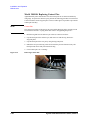
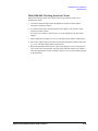
Model 300/400: Cleaning Contact Pins. . . . . . . . . . . . . . . . . . . . . . . . . . . . . . . . . . . . .2-27
Model 300/400: Replacing Contact Pins. . . . . . . . . . . . . . . . . . . . . . . . . . . . . . . . . . . .2-28
Model 300/400: Checking Interlock Circuit . . . . . . . . . . . . . . . . . . . . . . . . . . . . . . . . .2-29
3. Using Agilent iPACE Verification Tool
Overview . . . . . . . . . . . . . . . . . . . . . . . . . . . . . . . . . . . . . . . . . . . . . . . . . . . . . . . . . . . . . . . . . .3-4
Installation . . . . . . . . . . . . . . . . . . . . . . . . . . . . . . . . . . . . . . . . . . . . . . . . . . . . . . . . . . . . . . . .3-5
System Requirements . . . . . . . . . . . . . . . . . . . . . . . . . . . . . . . . . . . . . . . . . . . . . . . . . . . .3-5
Installation Procedure . . . . . . . . . . . . . . . . . . . . . . . . . . . . . . . . . . . . . . . . . . . . . . . . . . . .3-6
Start-Up. . . . . . . . . . . . . . . . . . . . . . . . . . . . . . . . . . . . . . . . . . . . . . . . . . . . . . . . . . . . . . . . . . .3-7
Required Tools . . . . . . . . . . . . . . . . . . . . . . . . . . . . . . . . . . . . . . . . . . . . . . . . . . . . . . . . . . .3-7
Kelvin Cable Output Signal . . . . . . . . . . . . . . . . . . . . . . . . . . . . . . . . . . . . . . . . . . . . . . . .3-7
Start-Up. . . . . . . . . . . . . . . . . . . . . . . . . . . . . . . . . . . . . . . . . . . . . . . . . . . . . . . . . . . . . . . . .3-8
Self-test . . . . . . . . . . . . . . . . . . . . . . . . . . . . . . . . . . . . . . . . . . . . . . . . . . . . . . . . . . . . . . . . . .3-9
Connection Check . . . . . . . . . . . . . . . . . . . . . . . . . . . . . . . . . . . . . . . . . . . . . . . . . . . . . . . . .3-10
Measurement Setup . . . . . . . . . . . . . . . . . . . . . . . . . . . . . . . . . . . . . . . . . . . . . . . . . . . . .3-10
Execution Procedure. . . . . . . . . . . . . . . . . . . . . . . . . . . . . . . . . . . . . . . . . . . . . . . . . . . . .3-10
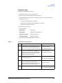
Troubleshooting. . . . . . . . . . . . . . . . . . . . . . . . . . . . . . . . . . . . . . . . . . . . . . . . . . . . . . . . .3-14
Noise Offset Measurement . . . . . . . . . . . . . . . . . . . . . . . . . . . . . . . . . . . . . . . . . . . . . . . . .3-16
Measurement Setup . . . . . . . . . . . . . . . . . . . . . . . . . . . . . . . . . . . . . . . . . . . . . . . . . . . . .3-16
Execution Procedure. . . . . . . . . . . . . . . . . . . . . . . . . . . . . . . . . . . . . . . . . . . . . . . . . . . . .3-17
Troubleshooting. . . . . . . . . . . . . . . . . . . . . . . . . . . . . . . . . . . . . . . . . . . . . . . . . . . . . . . . .3-18
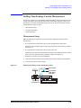
Settling Time/Leakage Current Measurement. . . . . . . . . . . . . . . . . . . . . . . . . . . . . . . . .3-19
Measurement Setup . . . . . . . . . . . . . . . . . . . . . . . . . . . . . . . . . . . . . . . . . . . . . . . . . . . . .3-19
Execution Procedure. . . . . . . . . . . . . . . . . . . . . . . . . . . . . . . . . . . . . . . . . . . . . . . . . . . . .3-20
Troubleshooting. . . . . . . . . . . . . . . . . . . . . . . . . . . . . . . . . . . . . . . . . . . . . . . . . . . . . . . . .3-21
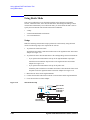
Using Batch Mode . . . . . . . . . . . . . . . . . . . . . . . . . . . . . . . . . . . . . . . . . . . . . . . . . . . . . . . .3-22
Setup . . . . . . . . . . . . . . . . . . . . . . . . . . . . . . . . . . . . . . . . . . . . . . . . . . . . . . . . . . . . . . . . . .3-22
To Perform Batch Mode Verification . . . . . . . . . . . . . . . . . . . . . . . . . . . . . . . . . . . . . . .3-23
To Create Batch File . . . . . . . . . . . . . . . . . . . . . . . . . . . . . . . . . . . . . . . . . . . . . . . . . . . . .3-24
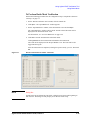
Reading Result Data . . . . . . . . . . . . . . . . . . . . . . . . . . . . . . . . . . . . . . . . . . . . . . . . . . . . . . .3-30
4. Agilent iPACE Verification Tool
Set Configuration Window. . . . . . . . . . . . . . . . . . . . . . . . . . . . . . . . . . . . . . . . . . . . . . . . . . .4-3
Contents - 2
Agilent 41000 Administration Guide, Edition 3
Contents
iPACE Verification Tool Window . . . . . . . . . . . . . . . . . . . . . . . . . . . . . . . . . . . . . . . . . . . . . .4-4
Selftest Tab . . . . . . . . . . . . . . . . . . . . . . . . . . . . . . . . . . . . . . . . . . . . . . . . . . . . . . . . . . . . .4-4
Verification Tab . . . . . . . . . . . . . . . . . . . . . . . . . . . . . . . . . . . . . . . . . . . . . . . . . . . . . . . . . .4-5
Batch Tab . . . . . . . . . . . . . . . . . . . . . . . . . . . . . . . . . . . . . . . . . . . . . . . . . . . . . . . . . . . . . . .4-6
Project Files . . . . . . . . . . . . . . . . . . . . . . . . . . . . . . . . . . . . . . . . . . . . . . . . . . . . . . . . . . . . . . .4-7
Project Items . . . . . . . . . . . . . . . . . . . . . . . . . . . . . . . . . . . . . . . . . . . . . . . . . . . . . . . . . . . . . .4-8
To Change Measurement Conditions. . . . . . . . . . . . . . . . . . . . . . . . . . . . . . . . . . . . . . . . .4-11
5. Measurement Techniques
Measurement Environments. . . . . . . . . . . . . . . . . . . . . . . . . . . . . . . . . . . . . . . . . . . . . . . . .5-3
Light and Noise . . . . . . . . . . . . . . . . . . . . . . . . . . . . . . . . . . . . . . . . . . . . . . . . . . . . . . . . . .5-3
Temperature and Humidity . . . . . . . . . . . . . . . . . . . . . . . . . . . . . . . . . . . . . . . . . . . . . . . .5-3
Floor Vibration . . . . . . . . . . . . . . . . . . . . . . . . . . . . . . . . . . . . . . . . . . . . . . . . . . . . . . . . . .5-3
Air Cleanliness. . . . . . . . . . . . . . . . . . . . . . . . . . . . . . . . . . . . . . . . . . . . . . . . . . . . . . . . . . .5-3
Kelvin Connections . . . . . . . . . . . . . . . . . . . . . . . . . . . . . . . . . . . . . . . . . . . . . . . . . . . . . . . . .5-4
About Kelvin Connections . . . . . . . . . . . . . . . . . . . . . . . . . . . . . . . . . . . . . . . . . . . . . . . . .5-4
To Make Kelvin Connections . . . . . . . . . . . . . . . . . . . . . . . . . . . . . . . . . . . . . . . . . . . . . . .5-5
To Control Switching Matrix . . . . . . . . . . . . . . . . . . . . . . . . . . . . . . . . . . . . . . . . . . . . . . .5-7
To Connect Ground Unit . . . . . . . . . . . . . . . . . . . . . . . . . . . . . . . . . . . . . . . . . . . . . . . . . . .5-9
Low Current Measurements . . . . . . . . . . . . . . . . . . . . . . . . . . . . . . . . . . . . . . . . . . . . . . . .5-11
Guard Technique . . . . . . . . . . . . . . . . . . . . . . . . . . . . . . . . . . . . . . . . . . . . . . . . . . . . . . . .5-11
Hold Time . . . . . . . . . . . . . . . . . . . . . . . . . . . . . . . . . . . . . . . . . . . . . . . . . . . . . . . . . . . . . .5-12
Offset Current Subtraction. . . . . . . . . . . . . . . . . . . . . . . . . . . . . . . . . . . . . . . . . . . . . . . .5-13
Low Resistance Measurements . . . . . . . . . . . . . . . . . . . . . . . . . . . . . . . . . . . . . . . . . . . . .5-16
To Select the Output Current Value . . . . . . . . . . . . . . . . . . . . . . . . . . . . . . . . . . . . . . . .5-17
Capacitance Measurements . . . . . . . . . . . . . . . . . . . . . . . . . . . . . . . . . . . . . . . . . . . . . . . .5-19
Capacitance Compensation Function . . . . . . . . . . . . . . . . . . . . . . . . . . . . . . . . . . . . . .5-19
Required Conditions . . . . . . . . . . . . . . . . . . . . . . . . . . . . . . . . . . . . . . . . . . . . . . . . . . . . .5-20
To Create Compensation Data File . . . . . . . . . . . . . . . . . . . . . . . . . . . . . . . . . . . . . . . . .5-22
To Perform Measurement and Compensation . . . . . . . . . . . . . . . . . . . . . . . . . . . . . . .5-26
agb220xa_compenC . . . . . . . . . . . . . . . . . . . . . . . . . . . . . . . . . . . . . . . . . . . . . . . . . . . . .5-28
agb220xa_selectCompenFile . . . . . . . . . . . . . . . . . . . . . . . . . . . . . . . . . . . . . . . . . . . . .5-28
6. Probe Card Interface
Product Overview . . . . . . . . . . . . . . . . . . . . . . . . . . . . . . . . . . . . . . . . . . . . . . . . . . . . . . . . . .6-3
Interlock Circuit . . . . . . . . . . . . . . . . . . . . . . . . . . . . . . . . . . . . . . . . . . . . . . . . . . . . . . . . . .6-5
Outside View and Dimensions . . . . . . . . . . . . . . . . . . . . . . . . . . . . . . . . . . . . . . . . . . . . . . .6-6
Specifications . . . . . . . . . . . . . . . . . . . . . . . . . . . . . . . . . . . . . . . . . . . . . . . . . . . . . . . . . . . . .6-9
Agilent 41000 Administration Guide, Edition 3
Contents - 3
Contents
Input/Output . . . . . . . . . . . . . . . . . . . . . . . . . . . . . . . . . . . . . . . . . . . . . . . . . . . . . . . . . . . .6-9
General Specifications . . . . . . . . . . . . . . . . . . . . . . . . . . . . . . . . . . . . . . . . . . . . . . . . . . .6-9
Accessories . . . . . . . . . . . . . . . . . . . . . . . . . . . . . . . . . . . . . . . . . . . . . . . . . . . . . . . . . . . . . .6-10
Options . . . . . . . . . . . . . . . . . . . . . . . . . . . . . . . . . . . . . . . . . . . . . . . . . . . . . . . . . . . . . . . . . .6-12
7. Service
Troubleshooting. . . . . . . . . . . . . . . . . . . . . . . . . . . . . . . . . . . . . . . . . . . . . . . . . . . . . . . . . . . .7-3
Safety Considerations . . . . . . . . . . . . . . . . . . . . . . . . . . . . . . . . . . . . . . . . . . . . . . . . . . . .7-4
Checking Power Distribution Unit (PDU). . . . . . . . . . . . . . . . . . . . . . . . . . . . . . . . . . . . .7-4
Troubleshooting . . . . . . . . . . . . . . . . . . . . . . . . . . . . . . . . . . . . . . . . . . . . . . . . . . . . . . . . .7-5
PDU and EMO . . . . . . . . . . . . . . . . . . . . . . . . . . . . . . . . . . . . . . . . . . . . . . . . . . . . . . . . . . . . .7-6
Power Distribution Unit (PDU) . . . . . . . . . . . . . . . . . . . . . . . . . . . . . . . . . . . . . . . . . . . . .7-7
Emergency off (EMO) Panel . . . . . . . . . . . . . . . . . . . . . . . . . . . . . . . . . . . . . . . . . . . . . .7-10
Replaceable Parts . . . . . . . . . . . . . . . . . . . . . . . . . . . . . . . . . . . . . . . . . . . . . . . . . . . . . . . . .7-11
System Cabinet . . . . . . . . . . . . . . . . . . . . . . . . . . . . . . . . . . . . . . . . . . . . . . . . . . . . . . . . .7-11
Cables and Accessories . . . . . . . . . . . . . . . . . . . . . . . . . . . . . . . . . . . . . . . . . . . . . . . . . .7-16
Probe Card Interface. . . . . . . . . . . . . . . . . . . . . . . . . . . . . . . . . . . . . . . . . . . . . . . . . . . . .7-17
Accessories for Performance Check . . . . . . . . . . . . . . . . . . . . . . . . . . . . . . . . . . . . . . .7-17
Replacement Procedure . . . . . . . . . . . . . . . . . . . . . . . . . . . . . . . . . . . . . . . . . . . . . . . . . . . .7-18
Safety Considerations . . . . . . . . . . . . . . . . . . . . . . . . . . . . . . . . . . . . . . . . . . . . . . . . . . .7-19
Required Tools . . . . . . . . . . . . . . . . . . . . . . . . . . . . . . . . . . . . . . . . . . . . . . . . . . . . . . . . . .7-20
To Remove Top Panel . . . . . . . . . . . . . . . . . . . . . . . . . . . . . . . . . . . . . . . . . . . . . . . . . . . .7-21
To Remove Top Cover . . . . . . . . . . . . . . . . . . . . . . . . . . . . . . . . . . . . . . . . . . . . . . . . . . . .7-22
To Remove Instruments . . . . . . . . . . . . . . . . . . . . . . . . . . . . . . . . . . . . . . . . . . . . . . . . . .7-23
To Remove EMO Panel . . . . . . . . . . . . . . . . . . . . . . . . . . . . . . . . . . . . . . . . . . . . . . . . . . .7-24
To Remove PDU . . . . . . . . . . . . . . . . . . . . . . . . . . . . . . . . . . . . . . . . . . . . . . . . . . . . . . . . .7-25
To Remove Measurement Cables . . . . . . . . . . . . . . . . . . . . . . . . . . . . . . . . . . . . . . . . . .7-26
To Replace Probe Card Interface Cables . . . . . . . . . . . . . . . . . . . . . . . . . . . . . . . . . . . .7-27
To Replace Contact Pins. . . . . . . . . . . . . . . . . . . . . . . . . . . . . . . . . . . . . . . . . . . . . . . . . .7-28
Measurement Cable Connections . . . . . . . . . . . . . . . . . . . . . . . . . . . . . . . . . . . . . . . . . . .7-29
Agilent E5270B Modules and Cables. . . . . . . . . . . . . . . . . . . . . . . . . . . . . . . . . . . . . . .7-32
System Rack and Instruments . . . . . . . . . . . . . . . . . . . . . . . . . . . . . . . . . . . . . . . . . . . . . .7-33
Contents - 4
Agilent 41000 Administration Guide, Edition 3
1
Introduction
Introduction
This chapter provides the following information of the Agilent 41000.
1- 2
•
“Product Overview”
•
“System Cabinet”
•
“Specifications”
•
“Accessories and Options”
Agilent 41000 Administration Guide, Edition 3
Introduction
Product Overview
Product Overview
Agilent 41000 series Integrated Parametric Analysis and Characterization Environment
(Agilent iPACE) is developed to realize the full 1 femtoamp measurement potential of the
semiconductor parameter analyzer through a switching matrix, probe card interface, and
probe card without any loss in measurement performance. The Agilent 41000 solutions
work with the 4155C, 4156C, or E5270B, and are available in both positioner and probe
card-based versions. See Table 1-1. These solutions include configurations for a variety of
measurement needs along with flexibility for future expansion.
For the expanded measurement requirements, you may add the other instruments, such as
digital voltmeters, pulse generators, and network analyzer. Also, you may use your own
test shell instead of the Agilent I/CV software that is the standard software used to control
the standard hardware (instruments) of the Agilent 41000.
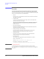
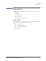
Figure 1-1
Agilent 41000 Product Image
In Figure 1-1, the Agilent 41000 contains the system cabinet, the instruments in the
cabinet, and the probe card interface that is placed on the auto prober. The auto prober is
not included in the Agilent 41000.
Agilent 41000 Administration Guide, Edition 3
1- 3
Introduction
Product Overview
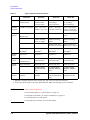
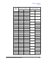
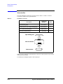
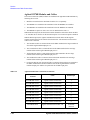
Table 1-1
Agilent 41000 Measurement Solutions
Model 100
Description ultra-precision,
positioner-based
Model 200
Model 300
Model 400
precision,
positioner-based,
for custom cables
semi-automated,
1 fA leakage,
probe card-based
semi-automated,
10 fA leakage,
probe card-based
Minimum
resolution
E5270B: 0.1 fA/0.5 µV 4156C: 1 fA/0.2 µV
E5270B: 1 fA/0.5 µV
4156C: 1 fA/0.2 µV
E5270B: 1 fA/0.5 µV
4155C: 20 fA/0.2 µV
4156C: 10 fA/0.2 µV
E5270B: 10 fA/0.5 µV
Standard
hardware
E5270B with
HRSMU/ASU1
E5270B or 4156C
E5270B or 4156C
E5270B, 4156C, or
4155C
B2200A switching
matrix, 12 outputs
B2200A switching
matrix
B2201A switching
matrix
B2220A probe card
B2220A probe card
interface (24 or 48 pin) interface (24 or 48 pin)
Rack, cables,
PDU/EMO2.
Rack, cables,
PDU/EMO2.
Rack, cables,
PDU/EMO2.
Rack, cables,
PDU/EMO2.
Standard
software
Agilent I/CV 2
Agilent I/CV 2
Agilent I/CV 2
Agilent I/CV 2
Furnished
software
performance integrity
verification tools
performance integrity
verification tools
performance integrity
verification tools
performance integrity
verification tools
Optional
hardware
4284A LCR meter
4284A LCR meter
4284A LCR meter
4284A LCR meter
41501B Expander
(HPSMU, MPSMU,
PGU)
41501B Expander
(HPSMU, MPSMU,
PGU)
41501B Expander
(HPSMU, MPSMU,
PGU)
Wafer prober and
positioner
Wafer prober and
sub-fA leakage probe
card
Wafer prober and low
leakage probe card
Third-party Wafer prober and
hardware
positioner
1. HRSMU is the high resolution source monitor unit. ASU is the atto sense and switch unit.
2. Items can be deleted. PDU is the power distribution unit. EMO is the emergency power-off button.
NOTE
About system components
For the system cabinet, see “System Cabinet” on page 1-9.
For the probe card interface, see “Probe Card Interface” on page 6-1.
For each instrument, see each manual.
For the Agilent I/CV software, see its on-line manual.
1- 4
Agilent 41000 Administration Guide, Edition 3
Introduction
Product Overview
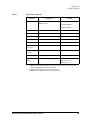
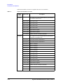
Table 1-2
Agilent 41000 Model 100
Function
Analyzer
Component
Option
Agilent E5270B+E5287A+E5288A: E5287A: HRSMU
HRSMU+ASU 1
E5280B: HPSMU 2
E5281B: MPSMU 3
Switch matrix
-
C-Meter
Agilent 4284A
DUT interface
-
Controller
Windows note PC
Optional
Control software
Agilent I/CV or I/CV Lite
Optional
Analyzer
connection
Kelvin connection ports
up to 8 ports
Verification
software
Agilent iPACE verification tool
Cabinet
1.6 m height
32 EIA unit
System power
supply
Power distribution unit (PDU)
100 V: 15 A,
100-120 V: 20 A, or
200-240 V: 10 A
Optional
1. HRSMU is the high resolution source monitor unit. ASU is the atto sense and
switch unit. Minimum 1 module is required.
2. HPSMU is the high power source monitor unit.
3. MPSMU is the medium power source monitor unit.
Agilent 41000 Administration Guide, Edition 3
1- 5
Introduction
Product Overview
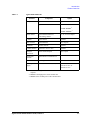
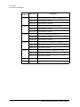
Table 1-3
Agilent 41000 Model 200
Function
Analyzer
Component
Option
Agilent 4156C
Agilent 41501B
Agilent E5270B
E5287A: HRSMU 1
E5280B: HPSMU 2
E5281B: MPSMU 3
Switch matrix
Agilent B2200A+B2210A
Femto leakage matrix
12, 24, 36 or 48 outputs
C-Meter
Agilent 4284A
Optional
DUT interface
-
Controller
Windows note PC
Optional
Control software
Agilent I/CV or I/CV Lite
Optional
Analyzer
connection
Kelvin connection ports
up to 4 ports
Verification
software
Agilent iPACE verification tool
Cabinet
1.6 m height
32 EIA unit
System power
supply
Power distribution unit (PDU)
100 V: 15 A,
100-120 V: 20 A, or
200-240 V: 10 A
1. HRSMU is the high resolution source monitor unit.
2. HPSMU is the high power source monitor unit.
3. MPSMU is the medium power source monitor unit.
1- 6
Agilent 41000 Administration Guide, Edition 3
Introduction
Product Overview
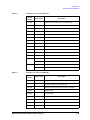
Table 1-4
Agilent 41000 Model 300
Function
Analyzer
Component
Option
Agilent 4156C
Agilent 41501B
Agilent E5270B
E5287A: HRSMU 1
E5280B: HPSMU 2
E5281B: MPSMU 3
Switch matrix
Agilent B2200A+B2210A
Femto leakage matrix
12, 24, 36 or 48 outputs
C-Meter
Agilent 4284A
Optional
DUT interface
Agilent B2220A
24 or 48 pins
Controller
Windows note PC
Optional
Control software
Agilent I/CV or I/CV Lite
Optional
Analyzer
connection
Kelvin connection ports
up to 4 ports
Verification
software
Agilent iPACE verification tool
Cabinet
1.6 m height
32 EIA unit
System power
supply
Power distribution unit (PDU)
100 V: 15 A,
100-120 V: 20 A, or
200-240 V: 10 A
1. HRSMU is the high resolution source monitor unit. Minimum 1 module is
required.
2. HPSMU is the high power source monitor unit.
3. MPSMU is the medium power source monitor unit.
Agilent 41000 Administration Guide, Edition 3
1- 7
Introduction
Product Overview
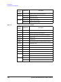
Table 1-5
Agilent 41000 Model 400
Function
Analyzer
Component
Option
Agilent 4155C or 4156C
Agilent 41501B
Agilent E5270B
E5287A: HRSMU 1
E5280B: HPSMU 2
E5281B: MPSMU 3
Switch matrix
Agilent B2201A+B2211A
14ch low leakage matrix
C-Meter
Agilent 4284A
Optional
DUT interface
Agilent B2220A
24 or 48 pins
Controller
Windows note PC
Optional
Control software
Agilent I/CV or I/CV Lite
Optional
Analyzer
connection
Kelvin connection ports
up to 4 ports
Verification
software
Agilent iPACE verification tool
Cabinet
1.6 m height
32 EIA unit
System power
supply
Power distribution unit (PDU)
100 V: 15 A,
100-120 V: 20 A, or
200-240 V: 10 A
1. HRSMU is the high resolution source monitor unit.
2. HPSMU is the high power source monitor unit.
3. MPSMU is the medium power source monitor unit.
1- 8
Agilent 41000 Administration Guide, Edition 3
Introduction
System Cabinet
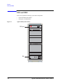
System Cabinet
This section explains important panel features of the Agilent 41000 system cabinet. See
Table 1-6 for the EMO/PDU operation and response.
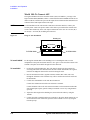
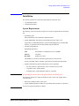
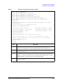
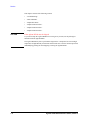
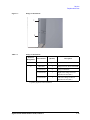
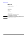
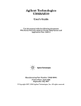
Figure 1-2
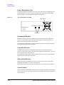
Emergency Power Off (EMO) Panel
+05647/'06219'4
1((10
'/1DWVVQP
.+0'KPFKECVQT
EMO Button
EMO button is used to turn off the power distribution unit (PDU) immediately. If the EMO
button is normal position (out position), AC power can be applied to the PDU. But if the
EMO button is pressed (set to the in position), AC power is shut off and the LINE indicator
is turned off.
LINE Indicator
LINE indicator lights when AC power is applied to the PDU.
INSTRUMENT POWER ON Button
INSTRUMENT POWER ON button is used to apply AC power to the instruments outlets
that are the inside of the system cabinet. If you press this button when the LINE indicator is
ON, AC power will be applied to the instruments outlets and the inside green LED will be
turned on.
INSTRUMENT POWER OFF Button
INSTRUMENT POWER OFF button is used to shut off AC power to the instruments
outlets. If you press this button, AC power to the instruments outlets will be shut off.
Agilent 41000 Administration Guide, Edition 3
1- 9
Introduction
System Cabinet
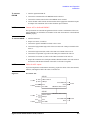
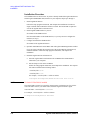
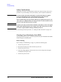
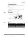
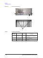
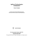
Power Distribution Unit
The power distribution unit (PDU) receives AC power from a power switchboard at your
site and distributes AC power to the power outlets in the system cabinet and the EMO
panel. See Table 1-6 for the EMO/PDU operation and response.
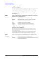
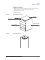
Figure 1-3
Power Distribution Unit (PDU)
/CKP5YKVEJ
1((
+PUVTWOGPVU %QPVTQNNGT
10
5[UVGO5YKVEJ
$TGCMGTU
Instruments Breaker
Instruments breaker protects the equipment connected to the instruments outlets from
excessive current. If the excessive current flows through the instruments breaker, AC
power to the instruments outlets will be shut off.
The instruments breaker and the controller breaker must be set to the ON position before
setting the main switch to the ON position.
Controller Breaker
Controller breaker protects the equipment connected to the controller outlets from
excessive current. If the excessive current flows through the controller breaker, AC power
to the controller outlets will be shut off.
The instruments breaker and the controller breaker must be set to the ON position before
setting the main switch to the ON position.
Main Switch/Breaker
Main breaker protects the PDU from excessive current. If the excessive current flows
through the main breaker, AC power will be shut off.
Set the main switch to the ON position, then press the system switch to turn the PDU on.
System Switch
System switch activates the PDU internal circuits. If you press the system switch when the
main switch is ON, AC power will be applied to the controller outlets and the inside LED
will be turned on.
1- 10
Agilent 41000 Administration Guide, Edition 3
Introduction
System Cabinet
External EMO Terminals
For connecting an extra emergency power off (EMO) button.
If you need to add an external EMO button, prepare a button and wire it between the Ext.
EMO terminals. Opening the terminals shuts off AC power to the PDU (same as setting the
EMO button to the in position), however it does not change the position of the EMO button
on the EMO panel.
When the terminals are shorted (normal condition), steady current (8 mA at 24 Vdc) flows
to the terminals.
Remote Control Terminals
For connecting an extra instrument power off button.
If you need to add an external instrument power off button, prepare a button and wire it
between the Remote Ctrl. terminals. Opening the terminals shuts off AC power to the
instruments outlets (same as pressing the INSTRUMENT POWER OFF button).
When the terminals are shorted (normal condition), steady current (8 mA at 24 Vdc) flows
to the terminals.
External Alarm 1 (NC) Terminals
For connecting a signal lamp or alarm that is used to notify that AC power to the PDU is
stopped.
The external alarm (Normally Closed) terminals are internally connected to a relay that is
closed in the normal condition (when AC power is applied) and is opened in the abnormal
condition (when AC power is stopped). The external alarm signal is not changed by
opening the Remote Control terminals.
The maximum input is 0.8 A at 24 Vdc. For the external alarm connection, see
Agilent 41000 Preinstallation Guide.
External Alarm 2 (NO) Terminals
For connecting a signal lamp or alarm that is used to notify that AC power to the PDU is
stopped.
The external alarm (Normally Open) terminals are internally connected to a relay that is
opened in the normal condition (when AC power is applied) and is closed in the abnormal
condition (when AC power is stopped). The external alarm signal is not changed by
opening the Remote Control terminals.
The maximum input is 0.8 A at 24 Vdc. For the external alarm connection, see
Agilent 41000 Preinstallation Guide.
NOTE
Ext. EMO, Remote Ctrl., and Ext. Alarm (NC and NO) Terminals
You can see the terminals on the rear panel of the PDU.
Agilent 41000 Administration Guide, Edition 3
1- 11
Introduction
System Cabinet
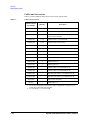
Table 1-6
PDU/EMO Operation and Response
Response
AC power to
controller
outlets
Operation
Sets Main Switch to ON
not supply
Presses System Switch
Presses ON Button on EMO Panel
Presses OFF Button on EMO Panel
AC power to
instruments
outlets
not supply
supply
supply
Ext. Alarm
1 (NC)
terminals
Ext. Alarm
2 (NO)
terminals
Open
Close
Close
Open
Open
Close
not supply
Opens Remote Ctrl.
Presses EMO Button or opens Ext. EMO
not supply
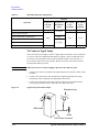
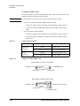
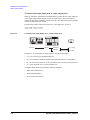
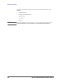
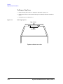
To Connect a Signal Lamp
This section shows an example to connect a signal lamp or alarm that is used to notify that
AC power to the power distribution unit (PDU) is stopped. Connect a signal lamp to the
Ext. Alarm 2 (NO) terminals as shown in the following example. Also see Figure 1-4.
Do not use the outlets in the system cabinet. Because AC power to the outlets will stop
when the EMO button is pressed.
WARNING
While at work, never connect anything to the power line outlet for safety.
1. Connect a wire between a terminal of the signal lamp and one of the Ext. Alarm 2 (NO)
terminals.
2. Connect a wire between the other terminal of the signal lamp and the power plug
terminal that will be connected to the NEUTRAL of the outlet.
3. Connect a wire between the other side of the Ext. Alarm 2 (NO) terminals and the
power plug terminal that will be connected to the LINE of the outlet.
Figure 1-4
Signal Lamp Connection Example
Emergency lamp
EMO switch
Outlet
To Ext. alarm 2 terminal
1- 12
Agilent 41000 Administration Guide, Edition 3
Introduction
Specifications
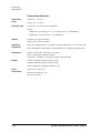
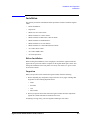
Specifications
The specifications are the performance standards or limits against which these units have
been tested. The supplemental information is not warranted, but provides useful
information about functions and performance.
Basic Functions
Configurations:
•
Probe card direct docking mechanism (Model 300/400)
•
High resolution DC measurement
•
High resolution capacitance measurement (with Agilent 4284A)
•
High performance resource switch capability (with Agilent E5288A for Model 100,
with Agilent B2200 for Model 200/300/400)
•
Pulsed force/measure (Model 200/300/400 with Agilent 41501B)
•
PC-based instrument control via a GUI (with Agilent I/CV)
•
Output pins: 24 or 48 pins (Model 300/400)
•
Input ports: 8 triaxial ports (0 to 4 ports selectable Kelvin input) and 6 coaxial ports
(Model 200/300/400)
•
Analyzer: Agilent E5270B, 4156C (Model 200/300/400), or 4155C (Model 400)
•
Additional instruments: Optional
•
Agilent 4284A Precision LCR Meter (as 1 MHz CMU)
•
Agilent 41501B SMU and Pulse Generator Expander (for 4155C/4156C)
•
PDU (with EMO): Optional
•
Measurement controller: Optional
•
Measurement control software: Optional
•
•
Agilent I/CV 3.0 (E5240C)
•
Agilent I/CV 3.0 Lite (E5241C)
Furnished software:
Measurement path control and path characteristics measurement software
(Agilent iPACE Verification Tool)
•
Furnished accessories:
Connection cables between instruments
Specification
Condition:
If not noted otherwise, the conditions for specifications and supplemental information are
as follows.
•
Temperature: 23 ° C ± 5 ° C
•
Relative Humidity (R.H.): 60 % and bellow
System components reference to the specification of each product.
Agilent 41000 Administration Guide, Edition 3
1- 13
Introduction
Specifications
General Specifications
Temperature
range:
Operation: 5 ° C to 35 ° C
Humidity range:
Operation: 5 % to 70 % R.H., no condensation
Storage: −20 ° C to 60 ° C
Storage:
Altitude:
•
Model 300: < 80 % R.H. at 35 ° C, < 60 % R.H. at 60 ° C, no condensation
•
Model 400: < 80 % R.H. at 60 ° C, no condensation
Operating: 0 to 2,000 m (6,500 ft)
Storage: 0 to 15,240 m (50,000 ft)
Regulatory
compliance:
Safety: Low Voltage Directive 73/23/EEC, 93/68/EEC EN61010-1, CSA C22.2 No.1010.1
Dimensions:
Cabinet: 1600 mm H × 500 mm W × 700 mm D
EMC: EMC Directive 89/336/EEC, 93/68/EEC EN61326-1, ICES-001, AS/NZS 2064.1
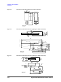
Probe Card Interface (for Model 300/400):
162 mm H × 390 mm W × 375 mm D, 220 mm H with contact pin
Weight:
Cabinet (for Model 100/200): 100 kg to 150 kg
Cabinet (for Model 300/400): 140 kg to 200 kg
Probe Card Interface (for Model 300/400): 15 kg
Power
requirement:
100-120 V 47-63 Hz: 20 A,
200-240 V 47-63 Hz: 10 A, or
100 V 47-63 Hz: 15 A
1- 14
Agilent 41000 Administration Guide, Edition 3
Introduction
Accessories and Options
Accessories and Options
The following is the furnished accessory for the Agilent 41000 Model 100/200.
•
Agilent 41000 System cabinet, 1 set
•
Agilent 41000 Manual CD-ROM, 1 ea.
•
Agilent iPACE Verification Tool, 1 ea.
•
Agilent 1250-2618 Triaxial (female to female) Adapter, 1 ea.
•
Agilent 1250-1708 Triaxial Open Connector, 1 ea.
The following is the furnished accessory for the Agilent 41000 Model 300/400.
•
Agilent 41000 System cabinet, 1 set
•
Agilent 41000 Manual CD-ROM, 1 ea.
•
Agilent iPACE Verification Tool, 1 ea.
•
Agilent 1250-2618 Triaxial (female to female) Adapter, 1 ea.
•
Agilent 1250-1708 Triaxial Open Connector, 1 ea.
•
Agilent E3140A Test Fixture Adapter, 1 ea.
•
Agilent E3142A Performance Check Fixture, 1 set
•
•
E3190-60042 PV Open Fixture, 1 ea.
•
E3144-60001 Card Fixture, 1 ea.
Agilent E3143A Connection Check Fixture, 1 set
•
E3141A (E3141-60005) Universal Fixture, 1 ea.
•
E3143-60001 Connection Check Fixture, 1 ea.
Agilent 41000 Administration Guide, Edition 3
1- 15
Introduction
Accessories and Options
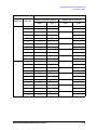
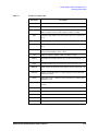
Options and available accessories for Agilent 41000 series are listed below.
Table 1-7
Options and Available Accessories
Model
Number
Option Item
C1231A
fA Leakage Low Current Measurement System Solution
for Positioner (Model 200)
C1231A-100
100 V Power Line
C1231A-120
120 V Power Line
C1231A-200
200 V Power Line
C1231A-240
240 V Power Line
C1231A-ABA
Paper Manual, English
C1231A-ABJ
Paper Manual, Japanese
C1231A-KLV
Number of Kelvin Connection Channels
C1232A
1- 16
Description
fA Leakage Low Current Measurement System Solution
with Probe Card (Model 300)
C1232A-003
3 m Cable for Probe Card Interface
C1232A-004
4 m Cable for Probe Card Interface
C1232A-012
Matrix 12 Outputs
C1232A-024
Matrix 24 Outputs
C1232A-036
Matrix 36 Outputs
C1232A-048
Matrix 48 Outputs
C1232A-100
100 V Power Line
C1232A-120
120 V Power Line
C1232A-200
200 V Power Line
C1232A-240
240 V Power Line
C1232A-ABA
Paper Manual, English
C1232A-ABJ
Paper Manual, Japanese
C1232A-KLV
Number of Kelvin Connection Channels
C1232A-NAN
Delete Analyzer
C1232A-NIF
Delete Probe Card Interface
Agilent 41000 Administration Guide, Edition 3
Introduction
Accessories and Options
Model
Number
Option Item
C1233A
10 fA Level Automated 14 channel Measurement Solution
for Probe Card (Model 400)
C1233A-003
3 m Cable for Probe Card Interface
C1233A-004
4 m Cable for Probe Card Interface
C1233A-012
Matrix 12 Outputs
C1233A-024
Matrix 24 Outputs
C1233A-036
Matrix 36 Outputs
C1233A-048
Matrix 48 Outputs
C1233A-100
100 V Power Line
C1233A-120
120 V Power Line
C1233A-200
200 V Power Line
C1233A-240
240 V Power Line
C1233A-ABA
Paper Manual, English
C1233A-ABJ
Paper Manual, Japanese
C1233A-KLV
Number of Kelvin Connection Channels
C1233A-NAN
Delete Analyzer
C1233A-NIF
Delete Probe Card Interface
C1234A
C1230A
Description
Ultra Low Current Measurement System Solution for
Positioner (Model 100)
C1234A-100
100 V Power Line
C1234A-120
120 V Power Line
C1234A-200
200 V Power Line
C1234A-240
240 V Power Line
C1234A-ABA
Paper Manual, English
C1234A-ABJ
Paper Manual, Japanese
C1230A-020
Delete Instrument Controller (Windows Note PC)
C1230A-PW0
No PDU
C1230A-PW1
PDU, 100 to 120 V, 20 A maximum
C1230A-PW2
PDU, 200 to 240 V, 10 A maximum
C1230A-PW3
PDU, 100 V, 15 A maximum
Agilent 41000 Administration Guide, Edition 3
1- 17
Introduction
Accessories and Options
Model
Number
Option Item
4155C
Semiconductor Parameter Analyzer (for Model 400)
4155C-ABA
Paper Manual Set, English
4155C-ABJ
Paper Manual Set, Japanese
4156C
Precision Semiconductor Parameter Analyzer
4156C-ABA
Paper Manual Set, English
4156C-ABJ
Paper Manual Set, Japanese
E5270B
8 Slot Precision Measurement Mainframe
E5270B-ABA
Paper Manual Set, English
E5270B-ABJ
Paper Manual Set, Japanese
B2200A
Femto Leakage Switch Mainframe (for Model 200/300)
B2200A-ABA
Paper Manual, English
B2200A-ABJ
Paper Manual, Japanese
B2201A
1- 18
Description
14ch Low Leakage Switch Mainframe (for Model 400)
B2201A-ABA
Paper Manual, English
B2201A-ABJ
Paper Manual, Japanese
E5240C
Agilent I/CV 3.0 Software
E5241C
Agilent I/CV 3.0 Lite Software
Agilent 41000 Administration Guide, Edition 3
Introduction
Accessories and Options
Table 1-8
Available Accessories for Model 100
Model
Number
Option Item
16493B
Coaxial Cable for 4155/4156 VSU/VMU/PGU
16493J
Interlock Cable
16493K
Kelvin Triaxial Cable
16493L
GNDU Cable
16494A
Triaxial Cable
16048D/E
Test Leads for 4284A
16495E
Blank Plate
16495F
Connector Plate (12 triaxial connectors)
16495G
Connector Plate (24 triaxial connectors)
16495F
Connector Plate (6 triaxial connectors)
16495G
Connector Plate (8 triaxial connectors)
16495K
Connector Plate with Universal Cable Holder
N1253A
N1254A
Table 1-9
Description
N1253A-100
Digital I/O T-cable
N1253A-200
Digital I/O BNC Box
N1254A-100
GNDU to Kelvin Adapter
N1254A-108
Magnet Stand for ASU
Available Accessories for Model 200
Model
Number
Option Item
Description
16493B
Coaxial Cable for 4155/4156 VSU/VMU/PGU
16493J
Interlock Cable for 4155/4156/E5270
16493K
Kelvin Triaxial Cable from 4156/E5270 to B2200
16493L
GNDU Cable
16494A
Triaxial Cable
16494B
Kelvin Triaxial Cable from B2200 output to 16495F/G
16494F
CMU Input Cable
16495E
Blank Plate
16495F
Connector Plate (12 triaxial connectors)
Agilent 41000 Administration Guide, Edition 3
1- 19
Introduction
Accessories and Options
Model
Number
Option Item
16495G
N1253A
N1254A
Table 1-10
Connector Plate (24 triaxial connectors)
N1253A-100
Digital I/O T-cable
N1253A-200
Digital I/O BNC Box
N1254A-100
GNDU to Kelvin Adapter
N1254A-107
Triax(m)-Triax(f) Adapter
Available Accessories for Model 300/400
Model
Number
Option Item
Description
16493B
Coaxial Cable for 4155/4156 VSU/VMU/PGU
16493J
Interlock Cable for 4155/4156/E5270
16493K
Kelvin Triaxial Cable from 4156/E5270 to B2200
16493L
GNDU Cable
16494A
Triaxial Cable
16494C
Kelvin Triaxial Cable from B2200 output to B2220A
16494F
CMU Input Cable
E3140A
Test Fixture Adapter
E3141A
Universal Test Fixture
E3142A
Performance Check Fixture for Low Current
E3143A
Connection Check Fixture Set for PCIF
N1253A
N1254A
1- 20
Description
N1253A-100
Digital I/O T-cable
N1253A-200
Digital I/O BNC Box
N1254A-100
GNDU to Kelvin Adapter
N1254A-107
Triax(m)-Triax(f) Adapter
Agilent 41000 Administration Guide, Edition 3
2
Installation and Operation
Installation and Operation
This chapter describes how to install the Agilent 41000 and how to operate the Agilent
41000 system cabinet.
NOTE
•
“Installation”
•
“Turning the PDU On and Off”
•
“Recovering from Power Line Problems”
•
“Maintenance”
About System Components
For the operation of the instruments (system components of the Agilent 41000), see
manuals of each instrument.
NOTE
Site Preparation
You have to perform the site preparation before you receive the Agilent 41000. The site
preparation information is described in Agilent 41000 Preinstallation Guide that must be
delivered to you as soon as the order is accepted.
CAUTION
Before Opening Packing Materials
The Agilent 41000 Model 200/300/400 contains the Agilent B2200 switching matrix that
uses the condensation sensitive electronic parts. The condensation will have a negative
impact on the Agilent B2200 to operate normally.
Do not open the packing materials, and leave the Agilent 41000 to acclimate it to the
installation environment (temperature and humidity). If it is opened without enough
acclimation, the Agilent B2200 may damage.
NOTE
Unpacking
After enough time to acclimate the Agilent 41000 to your installation environment, open
the packing materials as shown below.
1. Unpack the system cabinet and accessories.
2. Move them to the installation location.
For details, see Agilent 41000 Preinstallation Guide.
NOTE
Agilent 41000 Measurement Record of Integrity Verification
Keep this report that shows the measurement performance data, not specifications, when
the Agilent 41000 is shipped from the factory. The data is not guaranteed, but can be used
as a reference data when you verify the Agilent 41000 measurement performance by using
the Agilent iPACE Verification Tool.
2- 2
Agilent 41000 Administration Guide, Edition 3
Installation and Operation
Installation
Installation
This section provides the information and the procedures needed to install the Agilent
41000.
•
“Before Installation”
•
“Inspection”
•
“Model 100: To Connect ASU”
•
“Model 100/200: To Connect 16495”
•
“Model 100/200: To Make Your Connector Panel”
•
“Model 300/400: To Install B2220A”
•
“Model 300/400: To Use Test Fixture”
•
“Model 300/400: To Connect Measurement Cables”
•
“To Connect Power Cable”
•
“To Connect GPIB Cable”
•
“To Check Operation”
Before Installation
Before starting the installation, secure enough space to install the Agilent 41000 and
prepare the site power line and the receptacle for the Agilent 41000 power cable. Also
arrange the installation of the auto prober if necessary. For details, see Agilent 41000
Preinstallation Guide.
Inspection
When you open the box that contains the Agilent 41000, check the following:
1. Before unpacking any components, inspect all boxes for any signs of damage that
might have occurred during shipment such as:
•
Dents
•
Scratches
•
Cuts
•
Water marks
2. When you open the boxes that contain the Agilent 41000, check the components
against the contents lists that are attached to the boxes.
If anything is wrong, notify your local Agilent Technologies sales office.
Agilent 41000 Administration Guide, Edition 3
2- 3
Installation and Operation
Installation
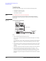
Model 100: To Connect ASU
The Agilent E5288A Atto Sense and Switch Unit (ASU) will add the 1 pA range to the
high resolution SMU (HRSMU) when it is connected between the HRSMU and the device
under test (DUT). And the ASU provides the input selection function when instruments are
connected to the SMU input and the AUX input.
NOTE
For the installation of the ASU and the connection to the DUT interface, contact your
favorite prober vender. The prober vender will be able to provide the DUT interface that
can be connected directly to the ASU output. Dimensions of the ASU are 132 mm (W) ×
50 mm (D) × 88.5 mm (H) excluding the connectors.
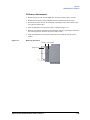
Figure 2-1
Image of ASU Installation
Shielding box
16495K
ASU
DUT interface
ASU
16495K
To E5270B/4284A
To E5270B/4284A
Prober
To install 16495K
Fix the Agilent 16495K Plate to the shielding box or something that will cover the
manipulators or the probe card (DUT interface). See Agilent 16495 Installation Guide. The
16495K is the plate used to block the light from the cable hole.
To install ASU
1. Fix the ASU in the shielding box. The ASU must be fixed to the best position for
accessing cables that come from the DUT interface and the instruments. The Agilent
N1254A-108 Magnetic Stand will be useful for fixing the ASU.
2. Pass the measurement cables (Agilent 16493M, 16494A, BNC cable, and so on)
through the cable hole of the 16495K. They will be connected between the ASU and
the instruments
3. Connect the 16493M cable to the ASU D-sub connector.
Connect the 16494A triaxial cable to the ASU Force terminal.
Connect the BNC cable to the ASU AUX In terminal. For the instrument without the
four-terminal-pairs inputs, open the CMU-pot terminal or cover it by using the BNC
open cap.
4. Adjust the cable length in the shielding box, and catch in the cables by using the
16495K.
5. Connect the cable extended from the DUT interface to the ASU output terminal. If you
do not make the Kelvin connection, open the Sense terminal or cover it by using the
triaxial open cap.
2- 4
Agilent 41000 Administration Guide, Edition 3
Installation and Operation
Installation
To connect
E5270B
1. Turn the Agilent E5270B off.
2. Connect the 16493M cable to the HRSMU D-sub connector.
3. Connect the 16494A triaxial cable to the HRSMU Force terminal.
4. Conect the BNC cable from the AUX In terminal to the appropriate instrument. Prepare
an adapter if the instrument does not have the BNC input connector.
NOTE
Connect ASU to dedicated HRSMU
The specifications are satisfied and guaranteed for the exclusive combination of the ASU
and the HRSMU. So confirm the serial number of the ASU and connect it to the dedicated
HRSMU properly.
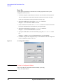
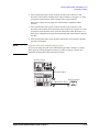
To connect 4284A
1. Turn the 4284A off.
2. Prepare two ASUs (#1 and #2).
3. Connect the Agilent 16048D/E test leads to the C meter.
4. Connect the high potential (Hp) cable of the test leads to the CMU-pot terminal of the
ASU #1.
5. Connect the high current (Hc) cable to the CMU-cur terminal of the ASU #1.
6. Connect the low potential (Lp) cable to the CMU-pot terminal of the ASU #2.
7. Connect the low current (Lc) cable to the CMU-cur terminal of the ASU #2.
8. Prepare the connection wire (both pin terminals) furnished with the ASU and connect it
between the CMU Return terminals of the ASU #1 and ASU #2 together.
NOTE
Cables for ASU outputs
To perform capacitance measurements accurately, prepare the cables of the same material,
structure, and length for both of the ASU #1 and ASU #2.
Figure 2-2
To Connect ASU
$68
7R&08
7R608
+F
+S
)RUFH
'VXE
&08FXU$8;,Q
&08SRW
)RUFH
)URP608
)RUFH&08$8;
6HQVH
7R'87
&085HWXUQ$8;&RPPRQ
$68
7R&08
7R608
/F
/S
&08FXU$8;,Q
&08SRW
)RUFH
)RUFH
'VXE
)URP608
Agilent 41000 Administration Guide, Edition 3
&085HWXUQ$8;&RPPRQ
)RUFH&08$8;
6HQVH
7R'87
2- 5
Installation and Operation
Installation
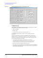
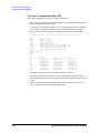
Model 100/200: To Connect 16495
The available connector plates are listed in Table 2-1. For connector plate installation
information, refer to Agilent 16495 Installation Guide.
For the connections between the instruments and the connector plate, use the measurement
cables listed in Table 2-2 and Table 2-3, and connect them to the appropriate connectors.
For the connections over the connector plate, see the following tables.
•
Table 2-4 shows the GNDU output connections over the connector plate.
•
Table 2-5 shows the SMU output connections over the connector plate.
•
Table 2-6 shows the AUX output connections over the connector plate.
Also make the interlock circuit and connect it to the instrument’s Interlock terminal. For
details, see “To Make an Interlock Circuit” on page 2-11. The Agilent E5270B/4155C/
4156C provides the interlock function. If the interlock terminal is open, the instrument
cannot force high voltage more than ±42 V.
NOTE
Making non-Kelvin connection
The Force terminals can be used to force and measure DC voltage or current. If you want to
simplify the cable connections, open the Sense terminals and connect the Force terminals
only to the connector plate by using the triaxial cables.
If you make the kelvin connection, use both Force and Sense terminals. Connecting the
Force and Sense lines together at the terminal of the device under test minimizes the
measurement error caused by the residual resistance of the connection cables. The kelvin
connection is effective for the low resistance measurement and the high current
measurement.
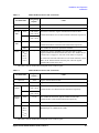
Table 2-1
Connector Plates
Model
Option Item1
16495F
16495F-001
Triax. (f-f) × 12, GNDU (f-f) × 1, Interlock (f) × 1
16495F-002
Triax. (f) × 12, GNDU (f) × 1, Interlock (f) × 1
16495G-001
Triax. (f-f) × 24, GNDU (f-f) × 1, Interlock (f) × 1
16495G-002
Triax. (f) × 24, GNDU (f) × 1, Interlock (f) × 1
16495H-001
Triax. (f-f) × 6, Coax. (f-f) × 6, GNDU (f-f) × 1, Interlock (f) × 1
16495H-002
Triax. (f) × 6, Coax. (f) × 6, GNDU (f) × 1, Interlock (f) × 1
16495J-001
Triax. (f-f) × 8, Coax. (f-f) × 4, GNDU (f-f) × 1, Interlock (f) × 1
16495J-002
Triax. (f) × 8, Coax. (f) × 4, GNDU (f) × 1, Interlock (f) × 1
16495K-001
Connector Plate with Rubber Holder
16495G
16495H
16495J
16495K
Connectors
1. Option 001 provides the through connectors except for the Interlock connector that provides the soldering patterns at the back side. For the option 002, the back of each connector is designed for soldering.
2- 6
Agilent 41000 Administration Guide, Edition 3
Installation and Operation
Installation
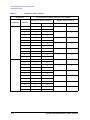
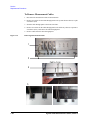
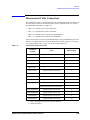
Table 2-2
Model 100 Measurement Cable Connections
Terminal name
Designation
on plate 1
Interlock
Intlk
Agilent 16493J Interlock Cable
GNDU
GNDU
Agilent 16493L GNDU Cable
E5270B
SMU
E5270B
SMU
4284A
Force
Odd number
from 1 to 24
Sense
Even number
from 1 to 24
Force
1 to 24
Cable
For Kelvin connection. Agilent 16493K Kelvin Triaxial Cable.
16495F/G/H/J allow 6/12/3/4 Kelvin triaxial connections respectively.
For non-Kelvin connection. Agilent 16494A Triaxial Cable.
16495F/G/H/J allow 12/24/6/8 triaxial connections respectively.
Sense
-
For non-Kelvin connection. Open Sense terminal.
Unknown
(HCUR,
HPOT,
LCUR,
LPOT)
-
Connect the Agilent 16048D/E Test Leads and connect it to the
Agilent E5288A Atto Sense/Switch Unit (ASU). See “Model 100: To
Connect ASU” on page 2-4. Two each of the ASUs are required.
Or connect the test leads and connect it to the AUX terminals (coaxial
BNC) of the 16495H/16495J connector plate. Then the Agilent
16494F CMU Cable can be used.
1. Maximum connector number labelled depends on the connector plate.
Table 2-3
Model 200 Measurement Cable Connections
Terminal name
Designation
on plate 1
Interlock
Intlk
Agilent 16493J Interlock Cable
GNDU
GNDU
Agilent 16493L GNDU Cable
B2200A
Output
B2200A
Output
4284A
Force
Odd number
from 1 to 24
Sense
Even number
from 1 to 24
Force
1 to 24
Cable
For Kelvin connection. Agilent 16494B Kelvin Triaxial Cable.
16495F/G allow 6/12 Kelvin triaxial connections respectively.
For non-Kelvin connection. Agilent 16494A Triaxial Cable.
16495F/G allow 12/24 triaxial connections respectively.
Sense
-
For non-Kelvin connection. Open Sense terminal.
Unknown
(HCUR,
HPOT,
LCUR,
LPOT)
-
Connect the Agilent 16494F CMU cable and connect it to the Agilent
B2200A Input 13 (CMH) and 14 (CML).
1. Maximum connector number labelled depends on the connector plate.
Agilent 41000 Administration Guide, Edition 3
2- 7
Installation and Operation
Installation
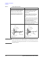
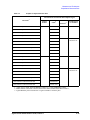
Table 2-4
GNDU Output Connections
Kelvin connections
non-Kelvin connections
Use a low-noise coaxial cable (Agilent part
number 8121-1189) from the connector to
the prober, socket, or DUT as shown.
Short the Sense and Force on the connector
as shown below. Measurement data will
include the residual resistance of the
connection wire.
To cancel the effects of cable resistance,
connect the Sense line and Force line as close
as possible to the terminal of the DUT.
Use AWG 22 single-strand insulated wire
(Agilent part number 8150-2639) from the
connector plate to the prober, socket, or
DUT.
For a quick connection where measurement
accuracy is not critical, connect only Force to
the DUT, without shorting the Sense and
Force. With this connection, the
measurement data will include residual
resistance from the connection cable between
the GNDU and the connector plate.
Insulator
Insulator
FORCE
FORCE
SENSE
SENSE
To
DUT
To
DUT
Wire
Plate
Triaxial Connector
CAUTION
Coaxial Cable
Plate
Triaxial Connector
GNDU can sink up to 4A for the Agilent E5270B or 1.6 A for the Agilent 41501B. Use the
Agilent 16493L GNDU cable to connect the GNDU to your connector plate or test fixture.
The maximum current rating of the triaxial cable is 1 A, so do not use the triaxial cable for
the GNDU connection.
2- 8
Agilent 41000 Administration Guide, Edition 3
Installation and Operation
Installation
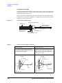
Table 2-5
SMU Output Connections
Kelvin connections
non-Kelvin connections
Use low-noise coaxial cable (Agilent part
number 8121-1191) from the connector to
the prober, socket, or DUT as shown.
The following figure is when the Kelvin
triaxial cable is used. If the triaxial cable is
used, connect the cable to the Force terminal
only. With this connection, the measurement
data will include residual resistance from the
connection cable.
To cancel the effects of cable resistance,
connect the Sense line and Force line as close
as possible to the DUT terminal.
To prevent oscillations, do not use cables
longer than 1.5 m.
To make accurate measurements when
applying high currents, extend the guard as
far as possible from the front panel connector
to the DUT. Physically stabilize the cables
with tape.
Use low-noise coaxial cable (Agilent part
number 8121-1191).
To make accurate measurements when
applying high currents, extend the guard as
far as possible from the front panel connector
to the DUT.
Insulator
GUARD
FORCE
Insulator
GUARD
FORCE
To
DUT
Triaxial
Connector
Coaxial Cable
To
DUT
Triaxial
Connector
SENSE
Plate
GUARD
Insulator
Coaxial Cable
SENSE
Plate
GUARD
Insulator
CAUTION
Never connect the Guard terminal to any output, including circuit common, chassis
ground, or any other guard terminal. Doing so will damage the SMU.
WARNING
Potentially hazardous voltages, up to ±100 V (±200 V for HPSMU), are present at the
Force, Sense, and Guard terminals.
To prevent electrical shock, do not expose these lines.
Before turning the instrument on, connect the Intlk terminal to a switch that turns off
when the shielding box access door is opened.
Before you touch any connections to these terminals, turn the instrument off,
disconnect the power cable, and discharge any capacitors.
Agilent 41000 Administration Guide, Edition 3
2- 9
Installation and Operation
Installation
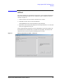
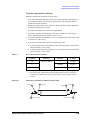
Low-Noise Coaxial Cable
For the extended measurement paths over the connector plate, use low-noise coaxial cable
(Agilent part number 8121-1191). This cable can maximize the guard effects and minimize
the impression of the external noise.
Figure 2-3 shows the cutting example of this cable. Key point is the isolation between the
conductive layer and the center conductor. So, cut and trim the end of the cable as shown in
this figure by using a cutter and so on.
Figure 2-3
Coaxial Cable Cutting Example
&RYHUKHUHXVLQJVOHHYH
,QVXODWRUEODFN
&HQWHUFRQGXFWRU
PLQPP
IRU)RUFH6HQVHVLJQDO
DSSUR[WRPP
2XWHUFRQGXFWRU
,QVXODWRUFOHDU
IRU*XDUGVLJQDO
&RQGXFWLYHOD\HU EODFN
Table 2-6
AUX (Coax. BNC) Output Connections
Wire connections
Coaxial connections
Use AWG 24 single-strand insulated wire
(Agilent part number 8150-0447) to connect
to a prober, socket, or DUT.
Regardless of the output impedance setting,
use a low-noise coaxial cable (Agilent part
number 8120-0102) from the connector to a
prober, socket, or DUT.
COMMON
COMMON
Insulator
Insulator
Signal Line
Signal Line
To
DUT
To
DUT
Wire
Coaxial Cable
Plate
BNC Connector
2- 10
Plate
BNC Connector
Agilent 41000 Administration Guide, Edition 3
Installation and Operation
Installation
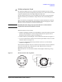
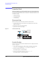
To Make an Interlock Circuit
The Agilent E5270B/4155C/4156C provides an interlock terminal to prevent you from
receiving an electrical shock from high voltage (more than ±42 V). If the interlock terminal
is open, the instrument cannot force high voltage more than ±42 V.
You must install an interlock circuit on a shielding box and connect it to the instrument’s
Interlock terminal to prevent hazardous voltages when the door of the shielding box is
open.
Figure 2-4 shows the pin assignments of the interlock connector mounted on a connector
plate or test fixture. The left side is the pin assignments seen from the plug side, and the
right side is the pin assignments seen from the soldering side.
WARNING
Potentially hazardous voltages may be present at the Force, Guard, and Sense
terminals when the interlock terminals are shorted.
Install the interlock circuit as follows:
1. Mount two mechanical switches on your shielding box, so that the switches close when
the door of the shielding box is closed, and open when the door is opened. For the
dimensions of the switch, see Figure 2-6 and Figure 2-7.
2. Mount an LED on your shielding box. For the dimensions of the LED, see Figure 2-5.
3. Use wire to connect the two switches in series between pin number 1 and 2 (or 3) of the
interlock connector. See Figure 2-4.
4. Use wire to connect the LED between pin number 4 and 5 (or 6) of the interlock
connector. See Figure 2-4.
If the instrument’s Interlock connector is connected to the interlock circuit, the instrument
cannot force more than ±42 V when the door is open. When the door is closed, the
instrument can force more than ±42 V.
When more than ±42 V is forced from an SMU, the LED lights to indicate high voltage
output.
Figure 2-4
Interlock Connector Pin Assignments
,QWHUORFN6ZLWFK
3OXJVLGH9LHZ
Agilent 41000 Administration Guide, Edition 3
/('
:LULQJ6LGH9LHZ
2- 11
Installation and Operation
Installation
Figure 2-5
Dimensions of the LED (Agilent part number 1450-0641)
11
5
5
Cathode(-)
Anode(+)
10
6
5.6
Units: mm
UGI01013,50x50
Dimensions of the Interlock Switch (Agilent part number 3101-0302)
4.75
4.3
10.3
2.8
Figure 2-6
2.8
6.35
3.1
6.5
18.8
5.5
10.3
NC
NO
15.9
Max 9
15.2
2.8
8.1
2.8
Switch off
Switch on
59.4
COM
3.1
22.2
27.8
Units: mm
UGI01011,85x60
Figure 2-7
10
37.8
Dimensions of the Interlock Switch (Agilent part number 3101-3241)
10.2
4.3
27.5
10.9
3.1
3.2
Switch off
Switch on
2.0
15.9
3.4
Units: mm
27.8
6.8
UGI01012,85x60
2- 12
Agilent 41000 Administration Guide, Edition 3
Installation and Operation
Installation
Model 100/200: To Make Your Connector Panel
This section is for you who do not use the Agilent 16495 connector plate.
If you want to mount connectors that accept the measurement cables from the instruments
directly on your own connector panel, test fixture, or shielding box, perform the following
procedure.
1. Select the appropriate parts for your application. See Table 2-7.
2. Make the holes and mount the connectors on your connector panel. See Table 2-8.
For Kelvin connections using the 4156C SMU, use Agilent 16493K Kelvin cable. A
Kelvin cable requires a Kelvin triaxial connector, which has two connector holes and
three screw holes.
3. Build the interlock circuit shown in “To Make an Interlock Circuit” on page 2-11.
4. Attach cables from the connectors to the DUT (device under test). See Table 2-4, Table
2-5, and Table 2-6.
Table 2-7
Recommended Parts
Usage
Making an interlock
circuit
GNDU output connections
SMU output connections
AUX output connections
Agilent Part No.
Description
1252-1419C
Interlock Connector (6 pin, female)
3101-0302 or 3101-3241
Switch
1450-0641
LED (VF ≅ 2.1 V @ IF = 10 mA)
8150-5680
Wire
1250-2457
Triaxial Connector (female)
8121-1189 or 8150-2639
Coaxial Cable or Wire
1250-2457
Triaxial Connector (female)
8121-1191
Low Noise Coaxial Cable
1250-0118
BNC Connector (female)
8150-0447
Wire
8120-0102 or 8121-1191
Low Noise Coaxial Cable
Agilent 41000 Administration Guide, Edition 3
2- 13
Installation and Operation
Installation
Table 2-8
Dimensions of Connector Holes
Interlock Connector (in mm)
1.8
5.1
8.2
BNC Connector (in mm)
12.1
12.8
Triaxial Connector (in mm)
10.3
∅11.3
Kelvin Triaxial Connector (in mm)
14
11
11
14
2.8
10.3
2 − ∅11.3
2- 14
∅3.2
2 − M3 x 0.5
Agilent 41000 Administration Guide, Edition 3
Installation and Operation
Installation
Model 300/400: To Install B2220A
This section describes how to install the Agilent B2220A probe card interface. This
information is for you who use the auto prober.
NOTE
Figure 2-8
For the installation of the B2220A and the connection to the DUT interface, contact your
favorite prober vender. The prober vender will be able to provide the DUT interface and
mechanisms required to install the B2220A.
•
“Requirements”
•
“Procedure”
•
“Before starting measurements”
Agilent B2200A Bottom View (Contact Side)
Requirements
The Agilent B2220A has been designed to contact its output pins directly with the probe
card. So, it must be mounted on the semi-auto prober or full-auto prober accurately and
carefully. The prober should have the following features. See Figure 2-9 and Figure 2-10.
•
•
Arm (with hinge, spring, and so on) that has the following functions.
•
To make contact with the probe card accurately and fix the B2220A on the prober
when performing test/measurement.
•
To face the B2220A contact side (bottom side) up when performing maintenance.
A pin that can press the B2220A’s prober sense switch when performing test/
measurement.
Agilent 41000 Administration Guide, Edition 3
2- 15
Installation and Operation
Installation
•
Pin holes for the B2220A’s guide pins.
•
Rack, cramp, or something to reduce stress to the input connectors/cables.
Enough space is required at the side of the prober to access the input cables and to perform
maintenance of the B2220A. See “Probe Card Interface” on page 6-1. Also see
Agilent 41000 Preinstallation Guide.
Figure 2-9
Mounting Agilent B2220A on Auto Prober 1
0DQLSXODWRU
+LQJH
Figure 2-10
Mounting Agilent B2220A on Auto Prober 2
Agilent B2220A Probe card interface
Position for
maintenance
Hinge or something
Position for testing
Pin for prober sense switch
and Holes for guide pins
Rack or
something
Auto prober
2- 16
Agilent 41000 Administration Guide, Edition 3
Installation and Operation
Installation
Procedure
The following procedure shows how to install the Agilent B2220A. Do not remove the
contact protector and the light shielding panel before starting the procedure. See also
“Probe Card Interface” on page 6-1.
1. Place the B2220A. Then, face the contact side (bottom side) up.
2. Unscrew and remove the contact protector from the bottom cover.
Keep the protector in trust. You may need it for move in future.
3. Mount the B2220A on your prober. See “Requirements” on page 2-15.
4. Connect the connection cables. See “Model 300/400: To Connect Measurement
Cables” on page 2-19.
Before starting measurements
The following procedure should be done before starting the measurements. However, the
procedure is not needed or should be changed if there is any additional mechanisms such as
the microscope on the B2220A in place of the light shielding panel.
1. Unscrew and remove the light shielding panel from the top cover.
2. Fix the probe card on the prober.
3. Make contact between the B2220A and the probe card.
4. Place the test wafer on the wafer chuck, and perform wafer alignment.
5. Replace and screw the light shielding panel.
6. Start the measurements.
Agilent 41000 Administration Guide, Edition 3
2- 17
Installation and Operation
Installation
Model 300/400: To Use Test Fixture
If you perform the measurement of the package devices, use the test fixture. Then, install
the Agilent B2220A as standalone, not on the prober.
Preparation
1. Prepare the following items.
•
Rubber feet, 4 ea. and bond or double-sided adhesive tape
The rubber feet should be attached on the corner of the B2220A top cover to protect
the jutty on the top cover.
•
Agilent E3140A Test Fixture Adapter, 1 ea.
•
Agilent E3141A Universal Test Fixture, 1 ea.
•
Socket(s) for your devices
•
Wire needed to connect between the E3141A’s soldering terminals and the socket
terminals
•
Solder, soldering bit, and so on
2. Design your test fixture and assemble it as show below.
a. Put the socket(s) on the top side of the E3141A universal test fixture, and fix it.
Then the device contacts must face up.
b. On the E3141A back side, place a wire between the E3141A’s soldering terminal
and the socket’s terminal, and solder it.
c. Repeat b as you designed.
Procedure
The following procedure shows how to install the Agilent B2220A. Do not remove the
contact protector and the light shielding panel before starting the procedure. See also
“Probe Card Interface” on page 6-1.
1. Place the B2220A Then, face the top cover up.
2. Fix a foot at a corner of the top cover using bond or double-sided adhesive tape. And
repeat this for four corners. Then, do not fix it on the light shielding panel.
3. Place the B2220A so that the contact side (bottom side) faces up.
4. Unscrew and remove the contact protector from the bottom cover.
Keep the protector in trust. You may need it for move in future.
5. Attach your test fixture on the E3140A Test Fixture Adapter.
6. Mount the test fixture adapter on the B2220A.
7. Connect the connection cables. See “Model 300/400: To Connect Measurement
Cables” on page 2-19.
2- 18
Agilent 41000 Administration Guide, Edition 3
Installation and Operation
Installation
Model 300/400: To Connect Measurement Cables
Connect measurement cables between the Agilent B2200 switch mainframe outputs and
the Agilent B2220A probe card interface inputs as shown below. For the cable connection
between instruments, see “Service” on page 7-1.
1. Connect the interlock cable between the Agilent 4155C/4156C/E5270B’s interlock
connector and the interlock connector of the Agilent B2220A probe card interface.
See Figure 2-11 and Figure 2-12.
2. Connect measurement cables between the Agilent B2200 outputs and the Agilent
B2220A inputs. Then, use the triaxial cables if there is no Kelvin connection in the
B2200 input, or else use the Kelvin triaxial cables. See Figure 2-12 and Table 2-10.
Table 2-9
Measurement Cables
B2220A connector
Cable
Input 1 to 48
(for 48 pin option)
Agilent 16494A triaxial cable for non-Kelvin connection
Input 2 to 48 1
(for 24 pin option)
Agilent 16494A triaxial cable for non-Kelvin connection
Interlock
Agilent 16494C Kelvin triaxial cable for Kelvin connection
Agilent 16494C Kelvin triaxial cable for Kelvin connection
Agilent 16493J interlock cable
1. There is no odd numbered connectors on the Agilent B2220A 24 pin option.
Only the even numbers are available for the 24 pin option.
Figure 2-11
Interlock Cable Connection on Agilent B2220A
WARNING
To prevent electrical shock during use, connect the interlock cable between the
interlock connector and the instrument’s interlock connector.
Agilent 41000 Administration Guide, Edition 3
2- 19
Installation and Operation
Installation
Figure 2-12
Measurement Cable Connection
$JLOHQW$
/&5PHWHU
$JLOHQW%$3UREHFDUGLQWHUIDFH
$JLOHQW(%
RU&&
%
3DUDPHWHU
DQDO\]HU
,QWHUORFN
3UREHFDUG
*1'8
:DIHU
WRSUREHUFKXFN
$XWRSUREHU
$JLOHQW%6ZLWFKPDLQIUDPH
Table 2-10
Agilent B2200 Outputs to Agilent B2220A Inputs Connections
B2200
output
2- 20
B2220A input:
non-Kelvin connection
B2220A input:
Kelvin connection
48 pin
24 pin
48 pin
24 pin
1
1
2
1
2
2
2
4
2
4
3
3
6
3
6
4
4
8
4
8
5
5
10
5
10
6
6
12
6
12
7
7
14
7
14
8
8
16
8
16
9
9
18
9
18
10
10
20
10
20
11
11
22
11
22
12
12
24
12
24
13
13
26
13
26
14
14
28
14
28
15
15
30
15
30
16
16
32
16
32
Agilent 41000 Administration Guide, Edition 3
Installation and Operation
Installation
B2200
output
B2220A input:
non-Kelvin connection
B2220A input:
Kelvin connection
48 pin
24 pin
48 pin
24 pin
17
17
34
17
34
18
18
36
18
36
19
19
38
19
38
20
20
40
20
40
21
21
42
21
42
22
22
44
22
44
23
23
46
23
46
24
24
48
24
48
25
25
-
25
-
26
26
-
26
-
27
27
-
27
-
28
28
-
28
-
29
29
-
29
-
30
30
-
30
-
31
31
-
31
-
32
32
-
32
-
33
33
-
33
-
34
34
-
34
-
35
35
-
35
-
36
36
-
36
-
37
37
-
37
-
38
38
-
38
-
39
39
-
39
-
40
40
-
40
-
41
41
-
41
-
42
42
-
42
-
43
43
-
43
-
44
44
-
44
-
45
45
-
45
-
46
46
-
46
-
47
47
-
47
-
48
48
-
48
-
Agilent 41000 Administration Guide, Edition 3
2- 21
Installation and Operation
Installation
To Connect GNDU Cable
The Agilent E5270B or 41501B’s GNDU (ground unit) is connected as shown below. The
GNDU is normally connected to the prober chuck.
NOTE
For the connection to the prober chuck, contact your favorite prober vender.
•
Non-Kelvin connection (Agilent E5270B or Agilent 41501B)
1. Connect the Agilent N1254A-107 adapter to the instrument’s GNDU connector.
2. Connect the Agilent 16493H GNDU cable between the adapter and the prober
chuck.
•
Kelvin connection (Agilent E5270B)
1. Connect the Agilent N1254A-100 adapter to the instrument’s GNDU connector.
2. Connect the Agilent 16493K Kelvin triaxial cable between the adapter and the
prober chuck.
Table 2-11
GNDU Cable and Adapter
Agilent model/part number
Non-Kelvin
connection
16493H
GNDU cable
N1254A-107 (P/N 1250-2654)
Triax(m)-Triax(f) adapter
16493K
Kelvin cable (max. 2.6 A)
Kelvin
connection
Figure 2-13
Description
N1254A-100
GNDU adapter
Adapters to Connect GNDU Cable
$JLOHQW1$7ULD[P7ULD[IDGDSWHU
WR*1'8FRQQHFWRU
IRUFH
WR+*1'8FDEOH
VHQVH
FRPPRQ
WULD[LDOPDOH
WULD[LDOIHPDOH
$JLOHQW1$*1'8WR.HOYLQDGDSWHU
IRUFH
WR*1'8FRQQHFWRU
FRPPRQ
VHQVH
WR..HOYLQWULD[LDOFDEOH
WULD[LDOPDOH
GXDOWULD[LDOIHPDOH
2- 22
Agilent 41000 Administration Guide, Edition 3
Installation and Operation
Installation
To Connect Power Cable
1. Prepare the site power line and the power receptacle for the Agilent 41000 power cable
as described in Agilent 41000 Preinstallation Guide.
2. Connect the Agilent 41000 power cable to the power receptacle. The power cable will
come from the bottom rear side of the Agilent 41000 system cabinet. It will be
connected to the rear panel of the power distribution unit (PDU).
3. This is only for the Agilent 41000 with the measurement controller option.
Connect the AC adapter to the measurement controller (Windows note PC) and connect
the power cable to the AC adapter. And then connect the power cable to your site
power line/receptacle directly.
NOTE
Note PC’s power cable
Power cable of the note PC AC adapter does not meet to the controller outlets on the PDU.
NOTE
If your Agilent 41000 do not have PDU option
Connect power cables for instruments and computer/controller to your site power line
directly.
To Connect GPIB Cable
•
If you use the Agilent 82357A USB/GPIB interface.
1. Install the Agilent VISA and SICL I/O libraries to your computer (controller). The
I/O libraries are furnished with the Agilent 82357A. This step is not needed for the
Agilent 41000 with the controller option, it has been installed in the computer.
2. Connect the USB connector of the Agilent 82357A to your computer (controller).
3. Connect the GPIB connector of the Agilent 82357A to an instrument of the Agilent
41000.
•
If you use the PCI GPIB interface card (Agilent 82350B or equivalent).
1. Install the Agilent VISA and SICL I/O libraries to your computer (controller). The
I/O libraries are furnished with the Agilent 82350B.
2. Install the PCI GPIB interface card to your computer (controller).
3. Connect the GPIB cable between your computer (controller) and an instrument of
the Agilent 41000.
To Check Operation
1. Install the Agilent 41000 iPACE Verification Tool software in your computer
(controller). This step is not needed for the Agilent 41000 with the controller option,
this software has been already installed in the computer.
2. Turn the Agilent 41000 on. See “Turning the PDU On and Off” on page 2-24.
3. Use the Agilent 41000 iPACE Verification Tool and check the operation. See “Using
Agilent iPACE Verification Tool” on page 3-1.
Agilent 41000 Administration Guide, Edition 3
2- 23
Installation and Operation
Turning the PDU On and Off
Turning the PDU On and Off
This section describes how to turn on or off your Agilent 41000 equipped with the power
distribution unit (PDU).
WARNING
•
“To Turn On your System”
•
“To Turn Off your System”
•
“To Turn Off your System in Emergency”
•
“To Reset EMO Button”
Electrical Work Type 3:
24 V is forced to the uninsulated parts of the EMO rear panel. Do not touch these
parts.
Figure 2-14
PDU and EMO
+05647/'06219'4
1((10
'/1DWVVQP
.+0'KPFKECVQT
2&7
/CKP5YKVEJ
$TGCMGTU
1((
10
5[UVGO5YKVEJ
+PUVTWOGPVU %QPVTQNNGT
To Turn On your System
1. Set the line ON/OFF switch of the all instruments in the system cabinet to the ON
position.
2. Set the PDU instruments breaker to the ON position. The PDU is located on bottom of
the system cabinet.
3. Set the PDU controller breaker to the ON position.
4. Set the PDU main switch to the ON position.
5. Press the PDU system switch. Then the inside LED will turn on, which means AC
power is applied to the controller outlets that are the inside of the system cabinet.
6. Press the INSTRUMENT POWER ON button on the EMO panel. The green LED in
the button will turn on, which means AC power is applied to the instruments outlets
that are the inside of the system cabinet.
2- 24
Agilent 41000 Administration Guide, Edition 3
Installation and Operation
Turning the PDU On and Off
To Turn Off your System
1. Press the INSTRUMENT POWER OFF button on the EMO panel. This shuts off AC
power to the instruments outlets.
2. Perform the shutdown procedure for your computer and turn off its line switch
3. Optional. Set the PDU main switch to the OFF position. This shuts off AC power to the
PDU.
CAUTION
Before performing step 3
If the PDU applies AC power to your computer, confirm that the computer has already shut
down and then perform step 3. Performing step 3 before shutdown may destroy the file
system of the computer.
To Turn Off your System in Emergency
The Agilent 41000 provides the emergency power off (EMO) system that can
automatically or manually stop power to the system cabinet PDU (power distribution unit)
in an emergency situation. This system is not available for the Agilent 41000 without the
PDU/EMO option.
For example, if an earthquake occurs, you can press the EMO button. Power supply to the
system stops immediately, thus preventing a potential fire caused by an electrical short
circuit.
To turn off your system in an emergency:
1. Press EMO button, which is the large red button on upper front of the system cabinet.
The EMO button is locked to the in position, which shuts off AC power to the PDU.
To Reset EMO Button
NOTE
Before resetting the EMO button
Before resetting the EMO button, make sure that no system instruments are damaged or
have recovered from any problems.
1. Rotate the EMO button clockwise to set it to the normal position (out position).
To turn the Agilent 41000 on, see “To Turn On your System” on page 2-24.
Agilent 41000 Administration Guide, Edition 3
2- 25
Installation and Operation
Recovering from Power Line Problems
Recovering from Power Line Problems
The PDU has protectors to detect power line problems and protect the system from
damage. These protectors stop the supply of power from the PDU to instruments and
computer/controller. The following conditions will stop the supply.
•
Excessive current flows through the breaker.
•
The EMO button is pressed.
•
The Ext. EMO terminal is open.
•
The Remote Ctrl. terminal is open.
After fixing problem, use following procedure to reset the breakers.
1. If the EMO button is set to the in position, perform the following step.
a. Set the PDU main switch to the OFF position.
b. Rotate the button clockwise to set it to the normal position (out position).
2. If the instruments breaker is the OFF position, set it to the ON position.
3. If the controller breaker is the OFF position, set it to the ON position.
4. Set the PDU main switch to the ON position.
5. Press the PDU system switch.
Figure 2-15
PDU and EMO
+05647/'06219'4
1((10
'/1DWVVQP
.+0'KPFKECVQT
2&7
/CKP5YKVEJ
$TGCMGTU
1((
10
5[UVGO5YKVEJ
+PUVTWOGPVU %QPVTQNNGT
2- 26
Agilent 41000 Administration Guide, Edition 3
Installation and Operation
Maintenance
Maintenance
Maintenance should be performed periodically to keep the Agilent 41000 in good
condition.
Performance Verification
Performance verification must be performed periodically so that the instruments satisfy the
specifications, and keep a good condition. It is recommended to perform the performance
verification once a year at least. For the performance verification, contact your nearest
Agilent Technologies Service Center. Trained service personnel will perform the
performance verification.
Cleaning
Before performing cleaning, turn off each instrument of the Agilent 41000, and disconnect
power cable from each instrument’s rear panel. Use a dry cloth to clean the external case
parts.
To prevent electrical shock, do not perform cleaning when each instrument is turned on,
and do not use a wet cloth.
Model 300/400: Cleaning Contact Pins
To clean contact pins and probe card contacts, prepare the isopropyl alcohol and a dryer.
Then clean them as shown below.
1. Spray the isopropyl alcohol to pins or contacts.
2. Dry them enough and carefully using the dryer.
Do not wipe with a cloth. It may expand dirty area.
Agilent 41000 Administration Guide, Edition 3
2- 27
Installation and Operation
Maintenance
Model 300/400: Replacing Contact Pins
Agilent B2220A probe card interface fixes the contact pins on its contact assemblies by
using rings. To replace the defective pins, perform the following procedure. You will need
a mini-screwdriver and a slip-joint pliers. Also use rubber gloves if possible to prevent the
contact pin from dirty.
NOTE
Contact Pins
The contact pin consists of the narrow part (pin) and the thick part (tube), and the pin can
be inserted into the tube. A spring in the tube works to keep pushing the pin out.
1. Hold the ring that fixes the defective pin. Then use a mini-screwdriver.
2. Clip the thick part of the defective pin, and remove it from the ring. Then use a
slip-joint pliers.
3. Clip the thick part of the new pin by using the slip-joint pliers.
4. Embed the new pin in the ring. Then do not insert the pin more than necessary. The
thick part must not be fully inserted into the ring.
5. Clean contact pins. See “Cleaning”.
Figure 2-16
Removing Contact Pins
&RQWDFWSLQ
5LQJIL[LQJFRQWDFWSLQ
2- 28
Agilent 41000 Administration Guide, Edition 3
Installation and Operation
Maintenance
Model 300/400: Checking Interlock Circuit
Perform the following steps to check the operation of the interlock circuit of your
measurement system.
1. Connect the interlock cable between the B2220A’s interlock connector and the
instrument’s interlock connector.
2. If you use the auto prober, place the B2220A on the prober to set the prober sense
switch to the make position.
If you use your test fixture, close the top cover of the Agilent E3140A Test Fixture
Adapter.
3. Set the instrument’s all output to 0 (zero) V. The high voltage indicator must turn off.
4. Set a source output voltage to the value more than the instrument’s interlock limit value
(e.g. 42 V). The high voltage indicator must turn on.
5. Release the B2220A from the prober or open the E3140A top cover to set the prober
sense switch to the break position. The high voltage indicator must turn off. And the
instrument should cause an error or change voltage to 0 (zero) V. The response depends
on the instrument.
Agilent 41000 Administration Guide, Edition 3
2- 29
Installation and Operation
Maintenance
2- 30
Agilent 41000 Administration Guide, Edition 3
3
Using Agilent iPACE Verification Tool
Using Agilent iPACE Verification Tool
This chapter explains how to use the Agilent iPACE Verification Tool.
NOTE
•
“Overview”
•
“Installation”
•
“Start-Up”
•
“Self-test”
•
“Connection Check”
•
“Noise Offset Measurement”
•
“Settling Time/Leakage Current Measurement”
•
“Using Batch Mode”
•
“Reading Result Data”
About Agilent iPACE Verification Tool
The Agilent iPACE Verification Tool is a non support sample program used to specify any
defective components of the Agilent 41000. And the program may be used to know the
measurement ability of whole system including the extended measurement paths and so on.
Use the verification tool to know the measurement ability of whole system after installation
or for the system administration.
Note that the verification tool cannot be used to verify the specifications of the Agilent
41000 and the system components (instruments).
NOTE
To Read This Section
For the Agilent 41000 Model 100 users, ignore the description about the Agilent B2200
and B2220A.
For the Agilent 41000 Model 200 users, ignore the description about the Agilent B2220A.
For the Agilent 41000 Model 300/400 (with option NIF) users, ignore the description about
the Agilent B2220A.
For all of the above systems, ignore the description of the test fixture attachment. Connect
the triaxial open cap to the following terminals.
•
For Model 100:
E5270B Force/Sense terminals
•
For Model 200 and Model 300/400 (with option NIF):
B2200 Output terminal (or Output N and N+1 terminals for the Kelvin connection)
where, N is an odd number from 1 to 11.
NOTE
Batch Mode Operation
The Agilent 41000 Model 300/400 (without option NIF) fully supports the batch mode
operation.
The Agilent 41000 Model 100/200 and the Model 300/400 (with option NIF) do not
support the connection check in the batch mode.
3- 2
Agilent 41000 Administration Guide, Edition 3
Using Agilent iPACE Verification Tool
NOTE
Agilent 41000 Measurement Record of Integrity Verification
Keep the Agilent 41000 Measurement Record of Integrity Verification report. The report
shows the following data measured at the factory. The values shown below are just sample.
•
Noise/Offset Record
#Source, Input, Slot, Output, IOffset[A], Noise[Sigma]
SMU1, 1, 1, 1, -2.115E-13, 8.01234E-15
•
•
IOffset[A]: Averaging value of the all data of the offset current measurement result.
•
Noise[Sigma]: Standard deviation value of the all data of the offset current
measurement result.
Settling/Leakage Record
#Source, Input, Slot, Output, ILeak[A], Vstep[V], ISettl(1s)[A],
ISettl(10s)[A]
SMU1, 1, 1, 1, -1.538E-13, 10, -2.55E-13, -2.20E-13
•
ILeak[A]: Averaging value of the last 10 data of the leakage current measurement
result.
•
ISettl(1s)[A]: Current measurement value of the first data measured after 1 second
passed from the measurement start.
•
ISettl(10s)[A]: Current measurement value of the first data measured after 10
second passed from the measurement start.
The report does not guarantee the measurement ability of the Agilent 41000. The data is
not the specifications.
Agilent 41000 Administration Guide, Edition 3
3- 3
Using Agilent iPACE Verification Tool
Overview
Overview
The Agilent iPACE Verification Tool can perform the following test and measurements.
This tool will be helpful to specify the defective components of the Agilent 41000 or to
know the measurement ability of whole system including the extended measurement paths
and so on. It is also useful for the system administration.
•
Self-test
Performs self-test of each instrument. You can see the test results on the Verification
Tool window or the log file.
•
Connection check
Controls the specified instrument to force voltage. You can see the results on the
Verification Tool window or the log file.
This function will be helpful to specify the defective components by monitoring the
voltage at the end of the probe card interface, measurement cables, instrument
terminals, and so on.
•
Noise offset measurement
Performs noise offset measurements. You can see the measurement results on the
Verification Tool window or the log file.
•
Settling time/leakage current measurement
Performs settling time and leakage current measurements. You can see the
measurement results on the Verification Tool window or the log file.
•
Automatic Execution
Performs any of the self-test, connection check, noise offset measurement,
settling time/leakage current measurement automatically.
•
Result Data Record
The result data will be logged into the log file. The default file is as follows.
folder: <installed folder>/bin
file name: iPACE Verification Tool (Report).txt
For example, <installed folder> will be as follows.
C:\Program Files\Agilent\iPACE Verification Tool A.01.00
NOTE
To Change the Log File
To change the log file, use the Open Report File dialog box opened by clicking
File > Open Report File. After changing the file name, the result data will be logged into
the new file.
3- 4
Agilent 41000 Administration Guide, Edition 3
Using Agilent iPACE Verification Tool
Installation
Installation
This section explains how to install the Agilent iPACE Verification Tool.
•
“System Requirements”
•
“Installation Procedure”
System Requirements
The following system environment is required to execute the Agilent iPACE verification
tool.
•
Operating System
Microsoft Windows 2000 or Windows XP Professional
•
Agilent GPIB (IEEE 488) Interface and Agilent IO Libraries M.01.01.04
Agilent 82357A USB/GPIB interface, E5810A LAN/GPIB gateway, 82350B GPIB
interface, or equivalent. These models include Agilent IO libraries.
•
Computer and peripherals
Minimum Requirements:
CPU
Intel Pentium or compatible processor, 300 MHz
Memory
128 Mbyte
Hard disk
20 Mbyte free space
CD-ROM drive is needed to install the Agilent iPACE verification tool.
Note PC furnished with the controller option satisfies the minimum requirements.
•
NOTE
Supported Instruments (Agilent 41000 iPACE system component)
•
DC source/monitor: Agilent 4155C, 4156C, E5270B, or E5270 series
•
Capacitance meter: Agilent 4284A
•
Switching matrix: Agilent B2200A, B2201A, or E5250A
If you modify the source code of the Agilent iPACE Verification Tool
The following software are required to modify the source code of the Agilent iPACE
verification tool.
•
Microsoft Visual Basic.NET version 2003
•
Agilent T&M Programmers Toolkit for Visual Studio.NET (W1140A or equivalent)
If you want, prepare and install the software.
Agilent 41000 Administration Guide, Edition 3
3- 5
Using Agilent iPACE Verification Tool
Installation
Installation Procedure
The installation flow is shown below. If you have already installed the Agilent IO libraries
and the Agilent GPIB (IEEE 488) interface on your computer, skip steps 1 through 3.
1. Install Agilent IO libraries.
Follow the setup program instructions, and complete the installation. Then do not
forget to add the VISACOM to the libraries to install. The VISACOM is required to
execute the Agilent iPACE verification tool.
2. Install Agilent GPIB interface to your PC.
See manual of the GPIB interface.
Note the model number of the GPIB interface, as you may need it to configure the
interface (in step 3).
3. Configure and check the GPIB interface.
See manual of the Agilent IO libraries.
4. Optional. Install Microsoft Visual Basic.NET and Agilent T&M Programmers Toolkit.
If you are going to modify the program code of the Agilent iPACE verification tool,
install the software. Follow the setup program instructions, and complete the
installation.
5. Install the Agilent iPACE verification tool.
a. Insert the Agilent iPACE Verification Tool CD-ROM to the CD-ROM drive
connected to your computer.
b. Execute Setup.exe file on the CD-ROM.
Follow the setup program instructions, and complete the installation. The required
files will be installed in the following folders.
<installed folder>\bin
<installed folder>\src
For example, <installed folder> will be as follows.
C:\Program Files\Agilent\iPACE Verification Tool A.01.00
NOTE
To check if VISACOM is installed
The VISACOM is required to execute the Agilent iPACE verification tool. Check if the
VisaCom folder exists. If you cannot find it, install the Agilent IO libraries again.
VisaCom folder: <installed folder>\VisaCom
For example, <installed folder> will be as follows.
C:\Program Files\Agilent\IO Libraries
3- 6
Agilent 41000 Administration Guide, Edition 3
Using Agilent iPACE Verification Tool
Start-Up
Start-Up
•
“Required Tools”
•
“Kelvin Cable Output Signal”
•
“Start-Up”
Required Tools
Before starting the verification, prepare the tools listed in Table 3-1. The tools except for
the multimeter are furnished with the Agilent 41000.
Table 3-1
Required Tools
Agilent model number / part number / description
Purpose
Qty.
E2373A basic 3.5 digit handheld multimeter or equivalent
connection check
1
E3140A test fixture adapter
for all
1
E3142A performance check fixture for low current
noise offset and
settling time/
leakage current
measurements
1
connection check
1
E3190-60042 PV open fixture 1
E3144-60001 card fixture (used to fix probe card) 2
E3143A connection check fixture set for PCIF
E3141A (E3141-60005) universal test fixture
for manual mode
E3143-60001 connection check fixture
for batch mode
1250-2618 triaxial female to female through adapter
1250-1708 triaxial open connector
for
troubleshooting
1
1
1. To perform the measurements at the tip of the B2220A pins, use E3190-60042.
2. To perform the measurements at the tip of the probe card, use E3144-60001.
NOTE
For the Agilent 41000 Model 100/200, ignore the Agilent E3140A/E3142A/E3143A. They
are required only for the Model 300/400.
Kelvin Cable Output Signal
Even if a Kelvin input is configured to the switch mainframe input, the all switch module
outputs must configure the Kelvin output. Then the Kelvin cable must be used to connect
between the switch module and the probe card interface. Do not use the triaxial cable.
In this connection, the verification tool controls the switches as shown below.
•
to apply the force/sense signals to each line of the Kelvin output properly.
•
to apply the non-Kelvin signal to both lines of the Kelvin output.
Agilent 41000 Administration Guide, Edition 3
3- 7
Using Agilent iPACE Verification Tool
Start-Up
Start-Up
To start up the Agilent iPACE verification tool, boot the program and set the system
configuration as shown below.
1. Click Start, Programs, Agilent iPACE Verification Tool, and iPACE Verification Tool.
The Set Configuration window and the iPACE Verification Tool window will open.
On the Set Configuration window, perform the following steps.
2. Specify the GPIB interface by using the GPIB Name combo box.
In Figure 3-1, the VISA name: GPIB0 is selected.
3. Check the check box left next to the Instrument combo box. Then do not check the
box for the instrument that is not installed in your Agilent 41000.
4. Specify the model number by using the Instrument combo box.
In Figure 3-1, the E5270B and B2200A are selected.
5. Specify the GPIB Address for each instrument by using the GPIB Address combo
box.
In Figure 3-1, address 17 is set to the E5270B and 22 is set to the B2200A.
6. Click OK to complete the configuration setup. Or click Cancel to cancel the setup. Then
the Set Configuration window will close.
Figure 3-1
Set Configuration Window
'#'$
#
$:#
NOTE
To Open Set Configuration Window
You can open the Set Configuration window manually by clicking
Config > Set GPIB Address...
3- 8
Agilent 41000 Administration Guide, Edition 3
Using Agilent iPACE Verification Tool
Self-test
Self-test
This section explains how to perform the self-test for the system component (instrument).
Perform the following procedure after the configuration setup is completed as shown in
“Start-Up” on page 3-8.
1. Click the ‘Selftest’ tab on the ‘iPACE Verification Tool’ window.
2. Click Run to start the self-test of the all instruments.
Clicking Break aborts the self-test and initializes each instrument.
3. After the test, the test result will be displayed on the ‘Report Window’ area. The result
will be also logged into the log file.
For the failed instrument, perform the self-test independently to specify the problem. For
the information about each instrument, see manual of each product. Also check the fail
status and contact your nearest Agilent Technologies Service Center.
Figure 3-2
iPACE Verification Tool window - Selftest tab
Agilent 41000 Administration Guide, Edition 3
3- 9
Using Agilent iPACE Verification Tool
Connection Check
Connection Check
This section explains how to perform the connection check. The connection check will be
performed by applying voltage from an instrument (voltage source) and monitoring voltage
at an output of the Agilent B2220A Probe Card Interface. A hand held multimeter is used
to measure the voltage.
•
“Measurement Setup”
•
“Execution Procedure”
•
“Troubleshooting”
Measurement Setup
Make the following measurement setup to perform the connection check.
1. Attach the Agilent E3141A Universal Fixture to the Agilent E3140A Test Fixture
Adapter. See Figure 3-3.
2. Mount the test fixture on the Agilent B2220A.
3. Open the lid of the test fixture adapter.
Figure 3-3
Connection Check Setup
$JLOHQW($
$JLOHQW($
(
$JLOHQW%$
3UREH&DUG,QWHUIDFH
3UREHU
Execution Procedure
Perform the following procedure after the instrument self-test is completed as shown in
“Self-test” on page 3-9.
1. On the ‘iPACE Verification Tool’ window, click the ‘Verification’ tab, and select
Connection Path from the Test Item combo box. See Figure 3-4.
2. Specify the voltage source by using Source.
The example in Figure 3-4 selects the SMU2.
3. Specify the switching matrix input port by using Input Port.
The example in Figure 3-4 selects the input port 2.
3- 10
Agilent 41000 Administration Guide, Edition 3
Using Agilent iPACE Verification Tool
Connection Check
4. Specify the switching matrix output port by using Output Slot and Output Ch.
The example in Figure 3-4 selects the output port 2 of the switch module installed in
the slot number 2.
5. Click Run. A dialog box opens to confirm the start of the connection check.
Click Cancel to cancel the connection check, or click OK to start.
DC voltage (approximately 10 V) will be applied to the specified output port. And a
dialog box opens to prompt you for DC voltage measurement.
6. Contact the following patterns on the Agilent E3141A universal fixture by using a hand
held multimeter, and measure DC voltage. The measured value should be about 10 V.
•
Force pattern (F) corresponding to the specified output port
•
Ground pattern (inside circle of the circle drawn by the 48 force patterns)
For the output ports and the force patterns, see Table 3-2.
7. Click OK if the measured value is about 10 V, or click Cancel if the value is abnormal.
Then the DC voltage output will be stopped.
The result will be displayed on the ‘Report Window’ area. The result will be also
logged into the log file.
8. Repeat 2 through 7 for the measurement paths you want to check.
Figure 3-4
iPACE Verification Tool window - Verification tab - Connection Path
Agilent 41000 Administration Guide, Edition 3
3- 11
Using Agilent iPACE Verification Tool
Connection Check
Table 3-2
Output Port and Force Pattern
Output ports
Force pattern (F) numbers on E3141A Universal fixture
B2220A: non-Kelvin connection
Output Slot
1
2
3- 12
B2220A: Kelvin connection
Output Ch
48 pin
24 pin
48 pin
24 pin
1
1
2
1
2
2
2
4
3
3
6
3
6
4
4
8
5
5
10
5
10
6
6
12
7
7
14
7
14
8
8
16
9
9
18
9
18
10
10
20
11
11
22
11
22
12
12
24
1
13
26
13
26
2
14
28
3
15
30
15
30
4
16
32
5
17
34
17
34
6
18
36
7
19
38
19
38
8
20
40
9
21
42
21
42
10
22
44
11
23
46
23
46
12
24
48
Agilent 41000 Administration Guide, Edition 3
Using Agilent iPACE Verification Tool
Connection Check
Output ports
Force pattern (F) numbers on E3141A Universal fixture
B2220A: non-Kelvin connection
Output Slot
Output Ch
3
4
B2220A: Kelvin connection
48 pin
24 pin
48 pin
24 pin
1
25
-
25
-
2
26
-
3
27
-
4
28
-
5
29
-
6
30
-
7
31
-
8
32
-
9
33
-
10
34
-
11
35
-
12
36
-
1
37
-
2
38
-
3
39
-
4
40
-
5
41
-
6
42
-
7
43
-
8
44
-
9
45
-
10
46
-
11
47
-
12
48
-
Agilent 41000 Administration Guide, Edition 3
27
-
29
-
31
-
33
-
35
-
37
-
39
-
41
-
43
-
45
-
47
-
3- 13
Using Agilent iPACE Verification Tool
Connection Check
Troubleshooting
If the proper voltage does not appear, it may be caused by the following reasons.
NOTE
•
Contact pins or connectors are dirty.
•
Contact pins or cables are defective.
•
Any instrument is defective.
If you found any defect in the system component
If you found any defect in the system component (DC source/monitor, LCR meter,
switching matrix, or probe card interface), contact your nearest Agilent Technologies
Service Center.
Figure 3-5
Connection Check Troubleshooting
'&VRXUFHPRQLWRU
6ZLWFKLQJPDWUL[
0HDVXUHPHQWFDEOH$
3UREHFDUGLQWHUIDFH
0HDVXUHPHQWFDEOH%
Perform the following step to specify the defective part.
1. Check if connection pins and connectors are clean.
If they are dirty, clean them and perform the connection check again. See “Cleaning”
on page 2-27.
If you find defective contact, replace the contact pin or measurement cable and perform
the connection check again. See “Model 300/400: Replacing Contact Pins” on page
2-28.
2. If the problem still remains, disconnect the measurement cable from the source output
connector (1 in Figure 3-5). Then, perform the connection check at the source output
connector.
If the proper voltage does not appear, the instrument (voltage source) will be defective.
3. If the measurement result is good, reconnect the cable to the connector 1. And
disconnect cable from the switching matrix input connector (2 in Figure 3-5). Then,
perform the connection check at the end of the measurement cable (A in Figure 3-5).
If the proper voltage does not appear, the measurement cable will be defective. Replace
the cable.
3- 14
Agilent 41000 Administration Guide, Edition 3
Using Agilent iPACE Verification Tool
Connection Check
4. If the measurement result is good, reconnect the cable to the connector 2. And
disconnect cable from the switching matrix output connector (3 in Figure 3-5). Then,
perform the connection check at the switching matrix output connector.
If the proper voltage does not appear, the switch module or mainframe will be
defective.
5. If the measurement result is good, reconnect the cable to the connector 3. And
disconnect cable from the probe card interface input connector (4 in Figure 3-5). Then,
perform the connection check at the end of the measurement cable (B in Figure 3-5).
If the proper voltage does not appear, the measurement cable will be defective. Replace
the cable.
6. If the measurement result is good, the probe card interface will be defective. Replace
the probe card interface.
NOTE
About the order of the troubleshooting procedure
If you want to change the order of the troubleshooting procedure, arrange it as you like.
Then, ignore the second paragraph in each step. You have to judge by yourself. The
judgement result depends on the order of the procedure.
'&VRXUFHPRQLWRU
6ZLWFKLQJPDWUL[
0HDVXUHPHQWFDEOH$
3UREHFDUGLQWHUIDFH
0HDVXUHPHQWFDEOH%
Agilent 41000 Administration Guide, Edition 3
3- 15
Using Agilent iPACE Verification Tool
Noise Offset Measurement
Noise Offset Measurement
This section explains how to perform the noise offset measurement. The noise offset
measurement will be performed by applying 0 V from the DC source/monitor and
monitoring current by the DC source/monitor when the Agilent B2220A outputs are open.
•
“Measurement Setup”
•
“Execution Procedure”
•
“Troubleshooting”
Measurement Setup
Make the following measurement setup to perform the noise offset measurement.
1. If you perform the measurement at the tip of the Agilent B2220A output pins:
Attach the E3190-60042 PV Open Fixture to the Agilent E3140A Test Fixture Adapter.
See Figure 3-6.
2. If you perform the measurement at the tip of the probe card:
Attach the probe card to the E3144-60001 card fixture. Then attach the fixture with the
probe card to the Agilent E3140A Test Fixture Adapter. See Figure 3-6.
3. Mount the test fixture on the Agilent B2220A.
4. Connect the interlock cable between the DC source/monitor and the Agilent B2220A.
5. Close the lid of the test fixture adapter.
Figure 3-6
Noise Offset Measurement Setup
$JLOHQW($
$JLOHQW($
(RU
(
$JLOHQW%$
3UREH&DUG,QWHUIDFH
3- 16
3UREHU
Agilent 41000 Administration Guide, Edition 3
Using Agilent iPACE Verification Tool
Noise Offset Measurement
Execution Procedure
Perform the following procedure after the instrument self-test is completed as shown in
“Self-test” on page 3-9.
1. On the ‘iPACE Verification Tool’ window, click the ‘Verification’ tab, and select
Noise from the Test Item combo box. See Figure 3-7.
2. Specify the voltage source by using Source.
The example in Figure 3-7 selects the SMU3.
3. Specify the switching matrix input port by using Input Port.
The example in Figure 3-7 selects the input port 3.
4. Specify the switching matrix output port by using Output Slot and Output Ch.
The example in Figure 3-7 selects the output port 3 of the switch module installed in
the slot number 3.
5. Click Run. A dialog box opens to prompt you for the measurement setup and the start
of the noise offset measurement.
Click Cancel to cancel the measurement, or click OK to start.
Clicking Break aborts the noise offset measurement and initializes the instruments.
The result will be displayed on the ‘Report Window’ area. The result will be also
logged into the log file.
Wait until a dialog box opens to notify the measurement completion. Then click OK.
6. Repeat step 2 through 5 for the measurement paths you want to measure.
NOTE
Measurement condition
Noise offset measurement condition is as follows.
Measurement mode
Spot measurement
Number of measurement points 50
Output voltage
0V
Measurement range
Auto
Integration time
50 PLC
Wait time
10 sec.
The SMU specified in the Source combo box will measure current in this condition.
NOTE
About measurement result data
IOffset value is given as the average of all measured current.
Noise value is given as the standard deviation value of all measured current.
Agilent 41000 Administration Guide, Edition 3
3- 17
Using Agilent iPACE Verification Tool
Noise Offset Measurement
Figure 3-7
iPACE Verification Tool window - Verification tab - Noise
Troubleshooting
If the result data is worse than the expected value, check your measurement environment.
The following factors can affect the measurement result.
•
Temperature change
•
Humidity change
•
Environmental noise such as pump, motor, light, and so on
See “Measurement Environments” on page 5-3 for the acceptable measurement
environments.
To perform troubleshooting, check the system component in the same manner as the
method described in “Troubleshooting” on page 3-14. Then, use the adapter/connector
listed below to make the open condition at the end of the measurement path such as the
cable end and the instrument output terminal.
•
Triaxial female to female Adapter (Agilent part number 1250-2618)
Connect this adapter to the measurement cable, then connect the triaxial open
connector to make the open condition at the end of the measurement cable.
•
Triaxial Open Connector (Agilent part number 1250-1708)
Connect this connector directly to the instrument connector to make the open condition
at the instrument output connector or to the above adapter to make the open condition
at the end of the measurement cable.
3- 18
Agilent 41000 Administration Guide, Edition 3
Using Agilent iPACE Verification Tool
Settling Time/Leakage Current Measurement
Settling Time/Leakage Current Measurement
This section explains how to perform the settling time/leakage current measurement. The
settling time/leakage current measurement will be performed by applying voltage (10 V)
from the DC source/monitor and monitoring current by the DC source/monitor when the
Agilent B2220A outputs are open.
•
“Measurement Setup”
•
“Execution Procedure”
•
“Troubleshooting”
Measurement Setup
Make the following measurement setup to perform the settling time/leakage current
measurement.
1. If you perform the measurement at the tip of the Agilent B2220A output pins:
Attach the E3190-60042 PV Open Fixture to the Agilent E3140A Test Fixture Adapter.
See Figure 3-8.
2. If you perform the measurement at the tip of the probe card:
Attach the probe card to the E3144-60001 card fixture. Then attach the fixture with the
probe card to the Agilent E3140A Test Fixture Adapter. See Figure 3-8.
3. Mount the test fixture on the Agilent B2220A.
4. Connect the interlock cable between the DC source/monitor and the Agilent B2220A.
5. Close the lid of the test fixture adapter.
Figure 3-8
Settling Time/Leakage Current Measurement Setup
$JLOHQW($
$JLOHQW($
(RU
(
$JLOHQW%$
3UREH&DUG,QWHUIDFH
Agilent 41000 Administration Guide, Edition 3
3UREHU
3- 19
Using Agilent iPACE Verification Tool
Settling Time/Leakage Current Measurement
Execution Procedure
Perform the following procedure after the instrument self-test is completed as shown in
“Self-test” on page 3-9.
1. On the ‘iPACE Verification Tool’ window, click the ‘Verification’ tab, and select
Settling/Leak from the Test Item combo box. See Figure 3-9.
2. Specify the voltage source by using Source.
The example in Figure 3-9 selects the SMU2.
3. Specify the switching matrix input port by using Input Port.
The example in Figure 3-9 selects the input port 2.
4. Specify the switching matrix output port by using Output Slot and Output Ch.
The example in Figure 3-9 selects the output port 2 of the switch module installed in
the slot number 2.
5. Click Run. A dialog box opens to prompt you for the measurement setup and the start
of the settling time/leakage current measurement.
Click Cancel to cancel the measurement, or click OK to start.
Clicking Break aborts the settling time/leakage current measurement and initializes the
instruments.
The result will be displayed on the ‘Report Window’ area. The result will be also
logged into the log file.
Wait until a dialog box opens to notify the measurement completion. Then click OK.
6. Repeat step 2 through 5 for the measurement paths you want to measure.
NOTE
Measurement condition
Settling time/leakage current measurement condition is as follows.
Measurement mode
Spot measurement
Total measurement time
100 sec (measurement repetition time)
Output voltage
10 V
Measurement range
MPSMU or HPSMU: 1nA Limited Auto
HRSMU: 100 pA Limited Auto
Integration time
2 PLC
Leak value
average of last ten measured points
The SMU specified in the Source combo box will measure current in this condition.
NOTE
About measurement result data
ILeak value is given as the averaging value of the last ten measurement data.
Time value is given as the time until the current measurement value is stable.
3- 20
Agilent 41000 Administration Guide, Edition 3
Using Agilent iPACE Verification Tool
Settling Time/Leakage Current Measurement
Figure 3-9
iPACE Verification Tool window - Verification tab - Settling/Leak
Troubleshooting
If the result data is worse than the expected value, check your measurement environment.
The following factors can affect the measurement result.
•
Temperature change
•
Humidity change
•
Environmental noise such as pump, motor, light, and so on
See “Measurement Environments” on page 5-3 for the acceptable measurement
environments.
To perform troubleshooting, check the system component in the same manner as the
method described in “Troubleshooting” on page 3-14. Then, use the adapter/connector
listed below to make the open condition at the end of the measurement path such as the
cable end and the instrument output terminal.
•
Triaxial female to female Adapter (Agilent part number 1250-2618)
Connect this adapter to the measurement cable, then connect the triaxial open
connector to make the open condition at the end of the measurement cable.
•
Triaxial Open Connector (Agilent part number 1250-1708)
Connect this connector directly to the instrument connector to make the open condition
at the instrument output connector or to the above adapter to make the open condition
at the end of the measurement cable.
Agilent 41000 Administration Guide, Edition 3
3- 21
Using Agilent iPACE Verification Tool
Using Batch Mode
Using Batch Mode
This section explains how to use the batch mode that is the function to perform the
self-test, connection check, noise offset measurement, and settling time/leakage current
measurement automatically. To use the batch mode, you need a batch file that is used to
specify the measurement items and the measurement conditions.
•
“Setup”
•
“To Perform Batch Mode Verification”
•
“To Create Batch File”
Setup
Make the following measurement setup to perform the verification by using the batch
mode. The following setup is not required for the self-test.
1. To perform the connection check:
Attach the E3143-60001 Connection Check Fixture to the Agilent E3140A Test Fixture
Adapter. See Figure 3-10.
2. To perform the noise offset measurement or the settling/leakage current measurement:
•
If you perform the measurement at the tip of the Agilent B2220A output pins:
Attach the E3190-60042 PV Open Fixture to the Agilent E3140A Test Fixture
Adapter. See Figure 3-10.
•
If you perform the measurement at the tip of the probe card:
Attach the probe card to the E3144-60001 card fixture. Then attach the fixture with
the probe card to the Agilent E3140A Test Fixture Adapter. See Figure 3-10.
3. Mount the test fixture on the Agilent B2220A.
4. Connect the interlock cable between the DC source/monitor and the Agilent B2220A.
5. Close the lid of the test fixture adapter.
Figure 3-10
Measurement Setup
$JLOHQW($
(RU
(RU
(
$JLOHQW%$
3UREH&DUG,QWHUIDFH
3- 22
3UREHU
Agilent 41000 Administration Guide, Edition 3
Using Agilent iPACE Verification Tool
Using Batch Mode
To Perform Batch Mode Verification
Perform the following procedure after the configuration setup is completed as shown in
“Start-Up” on page 3-8.
1. On the ‘iPACE Verification Tool’ window, click the ‘Batch’ tab.
2. Click Open.... The ‘Open Batch File’ window appears.
3. On the ‘Open Batch File’ window, select the batch file to use and click Open.
The ‘Open Batch File’ window will be closed. And the selected file name will be
displayed in the ‘Batch File Name’ field.
For the batch file, see “To Create Batch File” on page 3-24.
4. Click Run to start the measurements in the batch mode.
Clicking Break aborts the measurement and initializes the instruments.
The result will be displayed on the ‘Report Window’ area. The result will be also
logged into the log file.
After the measurement is completed, a dialog box opens to notify you of it. Then click
OK.
Figure 3-11
iPACE Verification Tool window - Batch tab
NOTE
Dialog Box
If plural test items are defined in a batch file, a dialog box will open at the beginning of
each test item. The dialog box will prompt you for the test fixture setup.
Agilent 41000 Administration Guide, Edition 3
3- 23
Using Agilent iPACE Verification Tool
Using Batch Mode
To Create Batch File
This section explains how to create the batch file.
•
“Batch File”
•
“Connection Check”
•
“To Create Batch File”
Especially, you have to understand the measurement mechanisms in the batch mode to
define the batch files to perform the connection check.
Batch File
Contents of the batch file are described in this section. Each line of the batch file should
contains the following information. The required parameter depends on the test item. The
parameters covered by [ ] can be ignored.
<test item>[,<s unit>,<s input port>,<s output slot>,<s output ch>[,
<unit>,<input port>,<output slot>,<output ch>]]
Table 3-3
Setup Parameters
Description 1
Parameter
test item
Test item. 0, 1, 2, or 255.
0: connection check
1: noise offset measurement
2: settling time/leakage current measurement
255: selftest
s unit
Source monitor unit. SMU1 to SMU8.
For the connection check, s unit specifies the voltage source.
SMU1 to SMU8, VSU1 to VSU2, PGU1 to PGU2, or CMU.
s input port
SWM input port number 2 that is used for the s unit connection. 1 to 14.
s output slot
SWM slot number that is used for the s unit connection. 1 to 4.
s output ch
SWM output port number that is used for the s unit connection. 1 to 12.
unit
Voltmeter. SMU1 to SMU8, VMU1 to VMU2, or CMU.
if CMU is set to s unit, set CMU to unit too. Then the CMU performs the
resistance measurement, not the voltage measurement.
input port
SWM input port number that is used for the unit connection. 1 to 14.
output slot
SWM slot number that is used for the unit connection. 1 to 4.
output ch
SWM output port number that is used for the unit connection. 1 to 12.
1. Available values depend on the system component.
2. SWM means the switching matrix.
3- 24
Agilent 41000 Administration Guide, Edition 3
Using Agilent iPACE Verification Tool
Using Batch Mode
Setup Example
•
Connection check:
All parameters must be specified. The program ignores the line that contains the
improper value.
Example: 0,SMU1,1,2,12,SMU4,5,2,9
Example: 0,SMU1,1,2,12,SMU4,5,2,7
Example: 0,SMU1,1,2,12,SMU4,5,2,5
Example: 0,SMU1,1,2,12,SMU4,5,2,3
Example: 0,SMU1,1,2,12,SMU4,5,2,1
•
Noise offset measurement:
Specify the parameters test item to s output ch. The program ignores the line that
contains the improper value.
For the measurement without switching matrix, do not specify the parameters
s input port, s output slot, and s output ch. Then you cannot delete comma.
Example: 1,SMU1,1,1,1
Example: 1,SMU2,2,1,2
Example: 1,SMU1,,,
•
Settling time/leakage current measurement:
Specify the parameters test item to s output ch. The program ignores the line that
contains the improper value.
For the measurement without switching matrix, do not specify the parameters
s input port, s output slot, and s output ch. Then you cannot delete comma.
Example: 2,SMU1,1,1,1
Example: 2,SMU2,2,1,2
Example: 2,SMU1,,,
•
Self-test:
Specify test item only.
Example: 255
NOTE
Sample Batch File
The following sample batch file is installed in the following folder.
folder: <installed folder>/bin
file name: iPACE Verification Tool (Batch).txt
The contents of the sample batch file is shown in Figure 3-12.
Agilent 41000 Administration Guide, Edition 3
3- 25
Using Agilent iPACE Verification Tool
Using Batch Mode
Figure 3-12
Sample Batch File
# <test item>[,<unit>,<input port>,<output slot>,<output ch>[,<unit>,<input port>,
<output slot>,<output ch>]]
#
# <test item>
: 0 (connection path), 1 (noise), 2 (settling) or 255 (selftest)
# <unit>
: SMU or CMU name (SMU1, SMU2, ..., CMU)
# <input port>
: input port number in matrix instrument
# <output slot> : output slot in matrix instrument
# <output ch>
: output channel in matrix instrumentthe
# <unit>
: SMU or CMU name (SMU1, SMU2, ..., CMU) (used by connection path)
# <input port>
: input port number in matrix instrument (used by connection path)
# <output slot> : output slot in matrix instrument (used by connection path)
# <output ch>
: output channel in matrix instrument (used by connection path)
255
0,SMU1,1,1,12,SMU2,2,1,10
0,SMU1,1,1,8,SMU2,2,1,6
0,SMU1,1,1,4,SMU2,2,1,2
0,SMU3,3,2,12,SMU4,4,2,10
0,SMU3,3,2,8,SMU4,4,2,6
0,SMU3,3,2,4,SMU4,4,2,2
0,CMU,9,3,12,CMU,1,3,10
0,CMU,9,3,8,CMU,1,3,6
0,CMU,9,3,4,CMU,1,3,2
1,SMU1,1,1,2
1,SMU2,2,1,2
1,SMU3,3,1,2
1,SMU4,4,1,2
2,SMU1,1,1,2
2,SMU2,2,1,2
2,SMU3,3,1,2
2,SMU4,4,1,2
3- 26
Agilent 41000 Administration Guide, Edition 3
Using Agilent iPACE Verification Tool
Using Batch Mode
Connection Check
To perform the connection check in the batch mode, the connection check fixture
(E3143-60001) must be connected to the Agilent B2220A probe card interface. The fixture
has four 12 pin block, and the pins are connected by the resistor as shown in Figure 3-13.
For the 48(24) pin configuration, the batch file should be created upon the following
connections of the voltage source (VS) and the voltmeter (VM).
Figure 3-13
•
VS to 12(12), and VM to 1 through 11 (2 through 10)
•
VS to 24(24), and VM to 13 through 23 (14 through 22)
•
VS to 36(36), and VM to 25 through 35 (26 through 34)
•
VS to 48(48), and VM to 37 through 47 (38 through 46)
E3143-60001 Internal Circuit and Voltage Source/Voltmeter Connection (non-Kelvin)
9ROWDJHVRXUFH
9
608)RUFH
608)RUFH
9PHDV
NOTE
5
5
5
5
5
5
5
5
5
5
5
5
5
5
5
5
5
5
5
5
5
5
5
5
5
5
5
5
5
5
5
5
5
5
5
5
5
5
5
5
5
5
5
5
5
5
5
5
DC Voltage Measurement Result
Without any system error, the measurement result (Vmeas) should be almost equal to the
Vcalc value given by the following formula. Then n is an integer of 1 to 11 that means the
number of resistors between the measurement pin and the ground.
Vcalc = 10 × n / 12 (V)
For the 24 pin configuration, Vcalc = 10 × n / 6 (V). Then n is an even number of 2 to 10.
Agilent 41000 Administration Guide, Edition 3
3- 27
Using Agilent iPACE Verification Tool
Using Batch Mode
If the system contains a source monitor unit (SMU) that is connected to the Agilent B2200
switch mainframe by using a Kelvin triaxial cable, the switch module output ports work as
the couple output port. See Figure 3-14. You can use one of the following SMUs for the
voltage source and the voltmeter.
(1) SMU connected to the Agilent B2200 by the Kelvin cable
(2) SMU connected to the Agilent B2200 by the triaxial cable (non-Kelvin)
The connection of Figure 3-14 (2, non-Kelvin) will be made by using the switch module.
The switch module and the instrument will be controlled by the program.
For the 48(24) pin configuration, the batch file should be created upon the following
connections of the voltage source (VS) and the voltmeter (VM). For each cases, the output
voltage (10 V) will be applied to the pin 11(10), 23(22), 35(34), or 47(46).
Figure 3-14
•
VS to 11-12 (10-12), and VM to 1-2 through 9-10 (2-4 or 6-8)
•
VS to 23-24 (22-24), and VM to 13-14 through 21-22 (14-16 or 18-20)
•
VS to 35-36 (34-36), and VM to 25-26 through 33-34 (26-28 or 30-32)
•
VS to 47-48 (46-48), and VM to 37-38 through 45-46 (38-40 or 42-44)
Connection of Couple Output Port
HYHQ
9ROWDJHVRXUFH
RU 6HQVH
5VI
RU608)RUFH
RGG
QRQ.HOYLQ
5
)RUFH
.HOYLQ
9ROWDJHVRXUFH608
9
5
5
9PHDV
HYHQ
RU QRQ.HOYLQ
6HQVH
5VI
608)RUFH
RGG
.HOYLQ
9ROWPHWHU608
NOTE
5
)RUFH
5R
5
DC Voltage Measurement Result
Without any system error, the measurement result (Vmeas) should be almost equal to the
Vcalc value given by the following formula. R is the resistance (about 50 kΩ) between the
test fixture pins, Ro is the resistance between the pins during the voltmeter is connected,
Ro=0 if the voltmeter is connected as shown in Figure 3-14 (2), Rsf is the resistance (about
10 kΩ, depends on SMU) between Force and Sense in the SMU, n is an odd number of 1 to
9 that means the number of resistors between the measurement pin and the ground.
For the 24 pin configuration, multiply R by two, and then n is 2 or 6.
Vcalc (V) = 10 × (n × R + Ro) / (10 × R + Ro)
Ro (Ω) = 1 / (1/R + 1/Rsf)
3- 28
Agilent 41000 Administration Guide, Edition 3
Using Agilent iPACE Verification Tool
Using Batch Mode
To Create Batch File
Open the ‘iPACE Verification Tool’ window, and perform the following step.
1. Click the ‘Batch’ tab.
2. Click Open.... The ‘Open Batch File’ window appears.
On the ‘Open Batch File’ window, select the batch file to use, and click Open.
The ‘Open Batch File’ window will be closed. And the selected file name will be
displayed in the ‘Batch File Name’ field.
3. Click Edit.... Then the Notepad will open. And it will show the code of the batch file.
4. Edit the batch file as you like.
See Table 3-3 for the meaning of parameters.
5. Save the batch file as the new file name.
NOTE
Creating Tips
If plural test items are defined in a batch file, a dialog box will open at the beginning of
each test item. The dialog box will prompt you for the test fixture setup.
To avoid this interrupt, it is recommended to create a batch file for each test item.
Agilent 41000 Administration Guide, Edition 3
3- 29
Using Agilent iPACE Verification Tool
Reading Result Data
Reading Result Data
This section explains the contents of the result data displayed on the ‘Result Window’ area
of the ‘iPACE Verification Tool’ window. The parameters covered by [ ] are optional.
The data will be logged into the log file. In the log file, the parameters are separated by tab.
•
Self-test:
Model Result
•
Connection check:
Source Input Slot Output Judge
•
Connection check (batch mode):
Source Input Slot Output
Unit
MInput MSlot MOutput VMeasure Status Time
•
Noise offset measurement:
Source Input Slot Output IMeasure Status Time
:
Source Input Slot Output IOffset Noise
50 data lines will be listed between the above lines.
•
Settling time/leakage current measurement:
Source Input Slot Output IMeasure Status Time
:
Source Input Slot Output ILeak VStep
Data lines for 100 seconds measurement will be listed between the above lines.
NOTE
Default Log File
In the default setting, the data will be logged into the following file.
folder: <installed folder>/bin
file name: iPACE Verification Tool (Report).txt
To change the log file, use the Open Report File dialog box opened by clicking
File > Open Report File. After changing the file name, the result data will be logged into
the new file.
3- 30
Agilent 41000 Administration Guide, Edition 3
Using Agilent iPACE Verification Tool
Reading Result Data
Table 3-4
Parameters in Report File
Parameter
Description
Model
Model number of the instrument that the self-test was performed.
Result
Self-test result. Pass or Fail.
Source
Source monitor unit or voltage source.
SMU1 to SMU8, VSU1 to VSU2, PGU1 to PGU2, or CMU.
Input
SWM input port number 1 that was used for the Source connection. 1
to 14.
Slot
SWM slot number that was used for the Source connection. 1 to 4.
Output
SWM output port number that was used for the Source connection. 1
to 12.
Judge
Label of the button clicked by the operator after the connection check
was performed manually. Ok or Cancel.
Unit
Voltmeter. SMU1 to SMU8, VMU1 to VMU2, or CMU.
MInput
SWM input port number that was used for the Unit connection. 1 to
14.
MSlot
SWM slot number that was used for the Unit connection. 1 to 4.
MOutput
SWM output port number that was used for the Unit connection. 1 to
12.
VMeasure
Voltage measurement data (V). Or the resistance measurement data
(Ω) if Unit is CMU.
Status
Status data of Unit. 0: normal. For the status data, see manual of the
instrument (Unit).
Time
Accumulated time from the beginning of the measurement (in
second).
IMeasure
Current measurement data.
IOffset
Averaging value of all measured current.
Noise
Standard deviation value of all measured current.
ILeak
Averaging value of the last ten measured current.
VStep
Voltage output value from Source.
1. SWM means the switching matrix.
Agilent 41000 Administration Guide, Edition 3
3- 31
Using Agilent iPACE Verification Tool
Reading Result Data
3- 32
Agilent 41000 Administration Guide, Edition 3
4
Agilent iPACE Verification Tool
Agilent iPACE Verification Tool
This chapter provides the reference information of the Agilent iPACE Verification Tool and
consists of the following sections.
NOTE
•
Set Configuration Window
•
iPACE Verification Tool Window
•
Project Files
•
Project Items
•
To Change Measurement Conditions
System Requirements
For the system requirements to perform the verification tool or modify the program code,
see “Installation” on page 3-5.
4- 2
Agilent 41000 Administration Guide, Edition 3
Agilent iPACE Verification Tool
Set Configuration Window
Set Configuration Window
This window is used to set the system configuration of the Agilent 41000.
GPIB Name
Selects the VISA name of the GPIB interface.
Instrument
Selects the instrument.
Check the check box of the left side. Then the Instrument combo box
will be active.
Figure 4-1
GPIB Address
Selects the GPIB address of the instrument set to the Instrument
combo box.
OK
Completes the configuration setup, and closes the Set Configuration
window.
Cancel
Cancels the setup, and closes the Set Configuration window.
Set Configuration Window
'#'$
#
$:#
Agilent 41000 Administration Guide, Edition 3
4- 3
Agilent iPACE Verification Tool
iPACE Verification Tool Window
iPACE Verification Tool Window
This section explains GUI of the iPACE Verification Tool window.
File
The Open Report File... menu opens the Open Report File window. On
the window, selects the log file used to save the measurement result
data.
The Exit menu closes the iPACE Verification Tool window.
Config
The Set GPIB Address... menu opens the Set Configuration window.
See “Set Configuration Window” on page 4-3.
Help
The About iPACE Verification Tool... menu displays the revision
information of the Agilent iPACE verification tool.
Report Window
Displays the measurement result data.
Selftest Tab
Executes the self-test.
Figure 4-2
4- 4
Run
Starts the self-test of the instruments listed in the text box upper than
the button.
Break
Aborts the execution of the self-test.
Selftest Tab
Agilent 41000 Administration Guide, Edition 3
Agilent iPACE Verification Tool
iPACE Verification Tool Window
Verification Tab
Executes the connection check, noise offset measurement, or settling time/leakage current
measurement.
Test Item
Selects the measurement item to perform.
Connection Path connection check
Figure 4-3
Noise
noise offset measurement
Settling/Leak
settling time/leakage current measurement
Source
Selects the voltage source (voltage output unit).
Input Port
Specifies the port number of the switch mainframe input port
connected to the voltage source.
Output Slot
Specifies the slot number of the mainframe card slot that installs the
switch module used for the measurement path.
Output Ch
Specifies the port number of the switch module output that will be the
end of the measurement path.
Run
Starts the specified measurement.
Break
Aborts the measurement execution.
Verification Tab
Agilent 41000 Administration Guide, Edition 3
4- 5
Agilent iPACE Verification Tool
iPACE Verification Tool Window
Batch Tab
Executes the measurement in the batch mode.
Figure 4-4
4- 6
Batch File Name
Displays the batch file to execute.
Open...
Opens the Open Batch File window. On the window, select the batch
file to execute.
Edit...
Opens the Notepad and displays the contents of the batch file that is
specified by the Batch File Name. You can edit the batch file on the
Notepad.
Run
Starts the specified measurement.
Break
Aborts the measurement execution.
Batch Tab
Agilent 41000 Administration Guide, Edition 3
Agilent iPACE Verification Tool
Project Files
Project Files
Agilent iPACE verification tool consists of the following projects.
•
Tool
Main project of the verification tool. Creates the GUI, controls the measurements,
displays the measurement results, creates the log file, and so on. This project imports
the Control project.
Location: <installed folder>/src/iPACE Verification Tool
•
Control
Measurement control subprograms are defined in this project. This project activates the
Body project.
Location: <installed folder>/src/iPACE Verification Control
•
Body
This project selects subprograms according to the setup of the GUI. This project
imports the Control and Instrument projects.
Location: <installed folder>/src/iPACE Verification Body
•
Instrument
Device (instrument) control subprograms are defined in this project. Controls a source
monitor unit, a LCR meter, and a switching matrix.
Location: <installed folder>/src/iPACE Verification Instrument
Then, <installed folder> is the folder where this program has been installed.
Figure 4-5
Relations of the Projects
$JLOHQWL3$&(9HULILFDWLRQ7RRO
7RRO
&RQWURO
*8,PHDVXUHPHQWFRQWURO
0HDVXUHPHQWFRQWURO
GDWDGLVSOD\ORJILOHHWF
VXESURJUDPV
DFWLYDWHV
LPSRUWV
,QVWUXPHQW
%RG\
LPSRUWV
'HYLFHLQVWUXPHQWFRQWURO
6XESURJUDPVHOHFWLRQIRU
VXESURJUDPV
PHDVXUHPHQWFRQWURO
LPSRUWV
Agilent 41000 Administration Guide, Edition 3
4- 7
Agilent iPACE Verification Tool
Project Items
Project Items
Each project consists of the project items shown in the following tables.
Table 4-1
•
Tool Project Items
•
Control Project Items
•
Body Project Items
•
Instrument Project Items
Tool Project Items
Item name
Description
Main.vb
Creates the iPACE Verification Tool window.
Config.vb
Creates the Set Configuration window.
Parameter.vb
Defines value of the instrument setup parameters (measurement
condition).
Imports modParameter (Parameter.vb) of the Control project.
Control.vb
Executes the selected measurement or the self-test.
Imports modControl (Control.vb) and modParameter
(Parameter.vb) of the Control project.
Data.vb
Collects and calculates the measurement result data.
File.vb
Defines a text file (log file) that saves the measurement results.
FileBind.vb
Keeps the contents of the batch file. Inherits File.vb.
FileConfig.vb
Stores the Set Configuration window setup data in the following
file. Inherits File.vb.
<installed folder>/bin/iPACE Verification Tool(Config)
FileTool.vb
Stores the measurement results in the following file. Also defines
title, label, and so on used in the file. Inherits File.vb.
<installed folder>/bin/iPACE Verification Tool(Report).txt
4- 8
Message.vb
Defines messages displayed on a message box or a dialog box.
dlgmsg.vb
Displays the Please Wait ... box when the system configuration is
confirmed.
i-pace27.ico
Defines the Agilent iPACE verification tool icon.
Agilent 41000 Administration Guide, Edition 3
Agilent iPACE Verification Tool
Project Items
Table 4-2
Control Project Items
Item name
Body.vb
Description
Collects the instrument control basic information; instrument
model, GPIB card number, address, program internal information,
and so on.
And activates the Body project.
Table 4-3
Control.vb
Defines the measurement control subprograms used for connection
path control, source output control, measurement data read, and so
on.
KeyCode.vb
Defines key code used by the measurement control subprograms.
Parameter.vb
Defines the current/voltage output range, the current/voltage/
resistance measurement range, and the several measurement
functions.
Socket.vb
Used for communication between the Tool project and the Body
project.
Time.vb
Performs the time out judgement.
Event.vb
Receives an event that notifies the update of an internal file created
by the Body project.
File.vb
Keeps data of an internal file created by the Body project.
Message.vb
Defines messages displayed on a message box or a dialog box.
Body Project Items
Item name
Main.vb
Description
This item is activated by Body.vb of the Control project.
Obtains the parameter values defined in the Tool project, and
activates Body.vb.
Body.vb
Performs Write and Read in System.vb.
Imports the Control project.
System.vb
Selects subprograms used for measurement control.
Imports the Control and Instrument projects. Also imports
modParameter (Parameter.vb) in the Control project.
File.vb
Keeps data of an internal file created by the Body project.
Message.vb
Defines messages displayed on a message box or a dialog box.
Agilent 41000 Administration Guide, Edition 3
4- 9
Agilent iPACE Verification Tool
Project Items
Table 4-4
Instrument Project Items
Item name
4- 10
Description
Inst.vb
Defines the common functions such as configuration confirmation,
error detection, initialization, self-test, and so on, in functions or
subprograms.
InstSpa.vb
Defines the functions for the source monitor unit in functions or
subprograms.
InstCmu.vb
Defines the functions for the LCR meter in functions or
subprograms.
InstMat.vb
Defines the functions for the switching matrix in functions or
subprograms.
Inst415x.vb
Defines the functions only for the 4155C/4156C in functions or
subprograms.
InstE527x.vb
Defines the functions only for the
E5270B/E5270A/E5272A/E5273A in functions or subprograms.
Inst4284.vb
Defines the functions only for the 4284A in functions or
subprograms.
InstB220x.vb
Defines the functions only for the B2200A/B2201A in functions or
subprograms.
InstE525x.vb
Defines the functions only for the E5250A in functions or
subprograms.
IoGpib.vb
Defines the GPIB common commands in functions or
subprograms.
IoSpa.vb
Defines the GPIB commands for the source monitor unit in
functions or subprograms.
IoCmu.vb
Defines the GPIB commands for the LCR meter in functions or
subprograms.
IoMat.vb
Defines the GPIB commands for the switching matrix in functions
or subprograms.
Io415x.vb
Defines the GPIB commands only for the 4155C/4156C in
functions or subprograms.
IoE527x.vb
Defines the GPIB commands only for the
E5270B/E5270A/E5272A/E5273A in functions or subprograms.
Io4284.vb
Defines the GPIB commands only for the 4284A in functions or
subprograms.
IoB220x.vb
Defines the GPIB commands only for the B2200A/B2201A in
functions or subprograms.
IoE525x.vb
Defines the GPIB commands only for the E5250A in functions or
subprograms.
Message.vb
Defines messages displayed on a message box or a dialog box.
Agilent 41000 Administration Guide, Edition 3
Agilent iPACE Verification Tool
To Change Measurement Conditions
To Change Measurement Conditions
The following procedure provides how to change the measurement condition and the
instrument setup. See Table 4-5 for the measurement condition setup parameters.
1. Make backup of all files in <installed folder>\src.
For example, copy them to <installed folder>\backup\src.
Then, <installed folder> is the folder where this program has been installed.
For example,
C:\Program Files\Agilent\iPACE Verification Tool A.01.00
2. Change the name of the following files. Add .org after .dll.
Folder: <installed folder>\bin
File: Agilent.IpaceVerificationControl.dll
File: Agilent.IpaceVerificationInstrument.dll
3. Open the following file on Microsoft Visual Basic .Net software.
Folder: <installed folder>\src\iPACE Verification Tool
File: Parameter.vb
4. Change the value of the parameters defined in the file as you want.
For the variables (measurement condition setup parameters), see Table 4-5.
5. Build the following projects in this order.
a. Instrument project
b. Control project
c. Body project
d. Tool project
6. Copy the following files to <installed folder>\bin.
Folder: <installed folder>\src\iPACE Verification Body\bin
File: Agilent.IpaceVerificationControl.dll
File: Agilent.IpaceVerificationInstrument.dll
Agilent 41000 Administration Guide, Edition 3
4- 11
Agilent iPACE Verification Tool
To Change Measurement Conditions
Table 4-5
Measurement Condition Setup Parameters
Variable name
Description
Default value
Connection check
VERIFY_CHECK_VS_FORCE
Voltage source output value (V)
10.0
VERIFY_CHECK_VS_COMPLIANCE
Voltage source compliance value (A)
0.001
VERIFY_CHECK_IS_FORCE
Voltage measurement unit output value (A)
0.0
VERIFY_CHECK_IS_COMPLIANCE
Voltage measurement unit compliance value (V)
20.0
Noise offset measurement
VERIFY_NOISE_INTEG_VALUE
Integration time (number of power line cycles)
50
VERIFY_NOISE_VS_FORCE
Voltage source output value (V)
0.0
VERIFY_NOISE_VS_COMPLIANCE
Voltage source compliance value (A)
VERIFY_NOISE_VS_NUMBER
Number of measurement points
VERIFY_NOISE_HOLD_TIME
Hold time (1.0 = 1 s)
0.001
50
10.0
Settling time/leakage current measurement
VERIFY_SETTLE_INTEG_VALUE
Integration time (number of power line cycles)
VERIFY_SETTLE_VS_FORCE
Voltage source output value (V)
10.0
VERIFY_SETTLE_VS_COMPLIANCE
Voltage source compliance value (A)
0.001
VERIFY_SETTLE_IM_TIME
Total measurement time (repetition time, 10000.0 = 1 s)
VERIFY_SETTLE_HOLD_TIME
Hold time (1.0 = 1 s)
0.0
VERIFY_LEAK_VS_NUMBER
Number of measurement data used to calculate the
ILeak value
10
4- 12
2
1000000.0
Agilent 41000 Administration Guide, Edition 3
5
Measurement Techniques
Measurement Techniques
This chapter explains the following measurement techniques.
5- 2
•
“Measurement Environments”
•
“Kelvin Connections”
•
“Low Current Measurements”
•
“Low Resistance Measurements”
•
“Capacitance Measurements”
Agilent 41000 Administration Guide, Edition 3
Measurement Techniques
Measurement Environments
Measurement Environments
It is important to prevent the device under test (DUT) from light, noise, vibration, and
temperature change to perform measurement, especially sensitive measurement such as
low current measurement and low resistance measurement. Before starting measurement:
Light and Noise
To prevent the DUT from light and noise, attach the light shielding panel (E3120-00211) to
the probe card interface (Agilent B2220A).
Temperature and Humidity
The measurement accuracy is specified at the following temperature and humidity.
Temperature:
23 °C ± 5 °C (73 °F ± 9 °F)
Humidity:
≤ 60% RH
Use air conditioner to keep the temperature constant. Then, prevent the instruments from
direct air flow. The air flow can cool down the instruments. And it will cause the
measurement error.
The following additional conditions should be satisfied for measuring low-current and
low-voltage.
Temperature change: Within ± 1 °C after the calibration
Temperature change period: ≥ 10 minutes
Humidity: ≤ 50%
Floor Vibration
The following vibration conditions should be satisfied for measuring low-current and
low-voltage. Keep away vibrator such as air pump and motor.
Floor vibration: ≤ 1 mG
Floor vibration transmission frequency: ≥ 10 Hz
Also, prevent the instruments and measurement cables from vibration. To do so, stabilize
the instrument rack or table that the instruments are placed, and stabilize the measurement
cables by using tape.
Air Cleanliness
The Agilent 41000 must be located in an area where the air purity meets or exceeds class
100,000 standards. Also, to ensure trouble-free disk and disk drive operation, system
controller peripherals should be located in an environment of similar air purity.
The following air cleanliness condition should be satisfied for measuring low-current and
low-voltage.
Air cleanliness: < class 10,000
Agilent 41000 Administration Guide, Edition 3
5- 3
Measurement Techniques
Kelvin Connections
Kelvin Connections
This section describes the Kelvin connections effective for the high current measurement
or the low resistance measurement. The Kelvin connection is available for the source
monitor unit (SMU) installed in the Agilent 4156C and E5270B.
•
“About Kelvin Connections”
•
“To Make Kelvin Connections”
•
“To Control Switching Matrix”
•
“To Connect Ground Unit”
About Kelvin Connections
When you measure a low resistance, high current flows through the DUT. This high current
increases the measurement error caused by the residual resistance of cables. To cancel the
effect of this resistance, you can use Kelvin connections (4-wire) which mean that the force
and sense lines are extended separately to the DUT. The next figure shows the equivalent
circuits for Kelvin and non-Kelvin connections.
•
For the non-Kelvin connection, the voltmeter measures the voltage drop of resistances
RF1, Rdut, and RF2.
•
For the Kelvin connection, the voltmeter measures the voltage drop of resistance Rdut
only. The impedance of the voltmeter is very high, so the voltage drop of resistances
RS1 and RS2 can be ignored.
5GXW
5GXW
5 )
5 )
5 6
5 )
5 )
5 6
9
9
DQRQ.HOYLQFRQQHFWLRQ
9
E.HOYLQFRQQHFWLRQ
The Kelvin connection is effective even when forcing voltage. The voltage drop due to the
residual resistance of the force line wiring is fed back to the voltage source via a
comparator in the sense line. The input impedance of comparator is high, and current flow
into the sense line is very low. So output error is not significant if the sense line wiring has
a residual resistance of 10 Ω or less. Therefore, the specified voltage appears at the sense
point (point where sense line contacts force line).
5- 4
Agilent 41000 Administration Guide, Edition 3
Measurement Techniques
Kelvin Connections
To Make Kelvin Connections
The instruments should be connected as shown in Figure 5-1 to make Kelvin connections.
Table 5-1 lists the connection cables required to make the Kelvin connection of the source
monitor unit (SMU).
Connect the 16493K Kelvin cable between the SMU and the switching matrix (SWM)
input. And connect the 16494C Kelvin cable between the SWM output and the probe card
interface (PC I/F) input. The Kelvin connection can be supported over the PC I/F output.
To make the sense points, see “Force-sense connections” on page 5-6.
Table 5-1
Required Cables for SMU Connection
From
Cable
To
SMU
16493K Kelvin triaxial cable
SWM Input 1
SWM Output
16494C Kelvin triaxial cable
PC I/F Input 2
1. Agilent B2200A/B2201A switching matrix (SWM) input pairs 1-2, 3-4, 5-6, or
7-8.
2. Agilent B2220A probe card interface (PC I/F) input pairs 1-2, 3-4, 5-6, ... , or
47-48 for 48 pin configuration, and 2-4, 6-8, 10-12, ... , or 46-48 for 24 pin
configuration.
Figure 5-1
Making Kelvin Connections
608)RUFH
6086HQVH
..HOYLQFDEOH
6:0.
6:01
6:0.
6:01
3&,)0$
&.HOYLQFDEOH
3&,)0
In Figure 5-1, K, N, M, and A are integer, and have the following meaning.
NOTE
•
K: 1 to 4. Used to specify the SWM input port.
•
N: 1 to 6× (number of modules installed in the mainframe from slot 1 sequentially).
•
M: 1 to 24 for the 48 pin PC I/F or the even number from 2 to 24 for the 24 pin PC I/F.
•
A: 1 for the 48 pin PC I/F or 2 for the 24 pin PC I/F.
Kelvin input-output paths
The Agilent B2220A probe card interface (PC I/F) uses two input-output paths to make one
Kelvin connection. Maximum 12 Kelvin paths are available for the 24 pin PC I/F, 24
Kelvin paths are available for the 48 pin PC I/F.
Agilent 41000 Administration Guide, Edition 3
5- 5
Measurement Techniques
Kelvin Connections
Force-sense connections
Kelvin output sense and force appear on the adjacent output pins of the Agilent B2220A
probe card interface. For example, if a Kelvin path is connected to the inputs 1-2, it is
extended to the output 1-2.
When the measurement is performed, the force and sense must be connected together.
There is the following ways to make the force-sense connections. Select the way suitable
for your measurement environment, and make it.
•
On the probe card
Design the probe card so that a probe needle is connected to both two adjacent contacts
on the probe card. See Figure 5-2. The guard terminals should be opened on the probe
card or should be connected to the guard terminal of the guarded probe needle.
•
On the wafer
Design the pattern so that a device terminal is connected to both two adjacent contact
pads. See Figure 5-3. The pads should be contacted by the adjacent probe needles on
the probe card, and the needles should be connected to the adjacent contacts on the
probe card.
The guard terminals should be opened on the probe card or should be connected to the
guard terminal of the guarded probe needle.
Figure 5-2
Making Sense Points on Probe Card
&RQWDFWIRU3LQ0
&RQWDFWIRU*XDUG
&RQWDFWIRU3LQ0$
Figure 5-3
Making Sense Points on Wafer
&RQWDFWSDGIRU3LQ0
&RQWDFWSDGIRU3LQ0$
NOTE
WRGHYLFH
Differences from the Agilent 4070 series
For the Agilent 4070 series, one matrix output provides the both force and sense pins. So
the maximum 48 Kelvin output ports can be made.
You can use the probe cards designed for the Agilent 4070. However, for the Kelvin
connection, the sense points (force-sense connections) must be made on the wafer as
shown in Figure 5-3.
5- 6
Agilent 41000 Administration Guide, Edition 3
Measurement Techniques
Kelvin Connections
To Control Switching Matrix
The Agilent B2200 switching matrix provides the couple mode function. When the couple
mode is ON, the matrix switches will be controlled to connect the specified couple input
port to the specified couple output port. The couple input ports have to be set to the input
ports used for the Kelvin connection.
To set couple input ports
There is two ways to set the couple input ports. First way is to set the couple ports
automatically by using the couple port detection capability. And the second way is to set
the couple ports manually.
•
Setting the couple ports automatically
Enter the :ROUT:COUP:PORT:DET command. The input ports connected to the
Kelvin cable will be detected automatically, and will be assigned as the couple input
ports.
•
Setting the couple ports manually
Enter the :ROUT:COUP:PORT card_number, ‘ports’ command to specify the couple
ports. For example, the following command sets two couple ports (input port pairs 1-2
and 3-4) for the all switch module installed in the Agilent B2200.
:ROUT:COUP:PORT ALL,’1,3’
To control Kelvin connection path
After the couple input ports are defined, set the couple mode ON by using the
:ROUT:COUP ON command. After that, the :ROUT:CLOS command will control the
switches to connect the specified couple input port to the specified couple output port, and
the :ROUT:OPEN command will control the switches to disconnect the specified couple
input port from the specified couple output port.
The following example connects the input ports 1 and 2 (couple input port) to the output
ports 11 and 12 respectively.
:ROUT:COUP:PORT ALL,’1,3’
:ROUT:COUP ON
:ROUT:CLOS (@00111)
Agilent 41000 Administration Guide, Edition 3
5- 7
Measurement Techniques
Kelvin Connections
To connect non-couple input ports to couple output ports
When you control the Agilent B2200 switching matrix to connect the non-couple input port
to the couple output port that the Kelvin cable is connected to, control the switches to
connect the input port to both lines of the Kelvin cable. They should be the same potential
when the measurement is performed.
The following example connects the input port 1 to the output ports 11 and 12.
:ROUT:CONN:RULE ALL,FREE
:ROUT:CLOS (@00111,00112)
Figure 5-4
Connecting Non-couple Input Ports to Couple Output Ports
6:0/
608)RUFH
$WULD[LDOFDEOH
6:01
6:01
3&,)0$
&.HOYLQFDEOH
3&,)0
In Figure 5-4, L, N, M, and A are integer, and have the following meaning.
•
L: 1 to 8. Used to specify the SWM input port.
•
N: 1 to 6× (number of modules installed in the mainframe from slot 1 sequentially).
•
M: 1 to 24 for the 48 pin PC I/F or the even number from 2 to 24 for the 24 pin PC I/F.
•
A: 1 for the 48 pin PC I/F or 2 for the 24 pin PC I/F.
And SMU, SWM, and PC I/F indicate the following instrument.
5- 8
•
SMU: Source Monitor Unit
•
SWM: Switching Matrix
•
PC I/F: Probe Card Interface
Agilent 41000 Administration Guide, Edition 3
Measurement Techniques
Kelvin Connections
To Connect Ground Unit
To use the ground unit (GNDU) of the Agilent 41501B or E5270B, connect the GNDU
output to the probe card interface (PC I/F) input, not the switching matrix input. See Figure
5-5. Table 5-2 lists the connection cables required to connect the GNDU.
Connect the adapter to the PC I/F input, then connect the GNDU cable between the GNDU
and the adapter. The Kelvin connection can be supported over the PC I/F output. To make
the sense points, see “Force-sense connections” on page 5-6.
Table 5-2
Required Cables for GNDU Connection
From
Cable
To
GNDU
16493L GNDU cable
PC I/F Input 1
E5250-60044 Triax-Dual Triax adapter
1. Agilent B2220A PC I/F input pairs 1-2, 3-4, 5-6, ... , or 47-48 for 48 pin configuration, and 2-4, 6-8, 10-12, ... , or 46-48 for 24 pin configuration.
Figure 5-5
Connecting GNDU
3&,)0$
*1'8)6
/*1'8FDEOH.HOYLQDGDSWHU
3&,)0
In Figure 5-5, M, and A are integer, and have the following meaning.
•
M: 1 to 24 for the 48 pin PC I/F or the even number from 2 to 24 for the 24 pin PC I/F.
•
A: 1 for the 48 pin PC I/F or 2 for the 24 pin PC I/F.
Agilent 41000 Administration Guide, Edition 3
5- 9
Measurement Techniques
Kelvin Connections
To make force-sense connection at PC I/F input
To keep the Kelvin connection up to the Agilent B2220A probe card interface (PC I/F)
input, not output, see Table 5-3 instead of Table 5-2.
Connect the adapter to the PC I/F input, then connect the GNDU cable between the GNDU
and the adapter. The path over the PC I/F input will be the non-Kelvin connection.
Table 5-3
Required Cables for GNDU Connection (non-Kelvin over PC I/F input)
From
Cable
To
GNDU
16493L GNDU cable
PC I/F Input
N1254A-107 Triax(m)-Triax(f) adapter 1
1. This adapter connects the center conductor (sense line) and the middle conductor (force line).
To pass GNDU output through SWM
If you have to pass the GNDU output through the Agilent B2200 switching matrix (SWM),
use the connection cables listed in Table 5-4.
Connect the GNDU Kelvin cable between the GNDU and the SWM input. And connect the
Kelvin cable between the SWM output and the PC I/F input. The Kelvin connection can be
supported over the PC I/F output. To make the sense points, see “Force-sense connections”
on page 5-6.
Table 5-4
Required Cables for GNDU Connection (through Agilent B2200)
From
Cable
To
GNDU
16493N-001 GNDU Kelvin cable for B2200
SWM Input 1
SWM Output
16494C Kelvin triaxial cable
PC I/F Input 2
1. Agilent B2200A/B2201A SWM input pairs 1-2, 3-4, 5-6, or 7-8.
2. Agilent B2220A PC I/F input pairs 1-2, 3-4, 5-6, ... , or 47-48 for 48 pin configuration, and 2-4, 6-8, 10-12, ... , or 46-48 for 24 pin configuration.
CAUTION
5- 10
Do not apply high current over the allowable current of the Agilent B2200. The high
current may damage the switch module.
Agilent 41000 Administration Guide, Edition 3
Measurement Techniques
Low Current Measurements
Low Current Measurements
This section describes the measurement techniques effective for the low current
measurement.
•
“Guard Technique”
•
“Hold Time”
•
“Offset Current Subtraction”
Guard Technique
The guard technique was developed to reduce the leakage current that occurs to the
measurement path. It is important to extend the guard pattern as close as possible to the
front edge of the probe needle to maximize the effect of the guard. This also reduces the
induced noise.
Extending guard pattern will reduce the leakage current as shown in Figure 5-6.
Figure 5-6
Guard Technique
I
Guard has not been extended.
Guard has been extended.
Guard
Force
t
CAUTION
Never connect the guard line/pattern to anything. Making connection will damage the unit.
WARNING
Do not touch the guard terminal/pattern with bare hands because you may be
shocked by high voltage. The potential is equal to the force level.
Agilent 41000 Administration Guide, Edition 3
5- 11
Measurement Techniques
Low Current Measurements
Hold Time
Dielectric absorption is considerable for the low current measurement. It may be
unexpected current caused by rapid voltage changes. To measure low current properly, it is
important to wait until when this transitional current settles down. So, the low current
measurement should be performed with the reasonable hold time setting. To find the
reasonable hold time, perform the dielectric absorption current measurement as shown
below.
1. Make open state at the end of the measurement path for the all output ports.
The measurement path should include the probe card, manipulator, or something to
contact pad/terminal of device under test (DUT).
2. Connect the current measurement path to a source monitor unit (SMU). Connect
unused paths to the ground unit (GNDU) or other SMU.
3. Set the dielectric absorption current measurement condition; integration time,
measurement range, output voltage, compliance, and so on.
•
The integration time should be enough long (e.g. 16 power line cycles). And the
value must be the same as the value set for the actual measurement.
•
The measurement range, output voltage, and compliance value must be the value
(e.g. 10 pA, 10 V, 10 mA) used for the actual DUT measurement.
•
All unused source outputs must be 0 V.
4. Enable time stamp function.
5. Apply voltage and reset time stamp. And then, perform current measurement and
record data (current and time stamp data). And repeat the current measurement until the
time stamp value is over 100 sec, for example.
6. Find the reasonable hold time from the measurement result. Or, plot the measurement
data on the current-time graph, and find the reasonable hold time.
Figure 5-7
Effect of Electric Absorption
A) Equivalent circuit when open
B) I-t characteristics observed
I
Open
A
R1
Rn
Cs
Dielectric absorption current
Hold time
Noise
C1
Cn
Pure leakage current
5- 12
t
Agilent 41000 Administration Guide, Edition 3
Measurement Techniques
Low Current Measurements
Offset Current Subtraction
Offset current of the measurement path is considerable for the low current measurement. It
is important to subtract the offset current (Iaverage) from the measurement data (Imeasure)
to approximate the real data (Iresult). This section introduces the following two ways.
•
“To subtract the open state offset current”
•
“To subtract the contact state offset current”
The offset current can be subtracted as shown in Figure 5-8.
Figure 5-8
Offset Current Subtraction
I
Offset current (Iaverage)
e.g. Iaverage = 5.9 fA
Standard deviation = 1.2 fA
5.9 fA
t
Agilent 41000 Administration Guide, Edition 3
I
<1.2 fA
Iresult = Imeasure Iaverage
V
5- 13
Measurement Techniques
Low Current Measurements
To subtract the open state offset current
In this way, the offset current is defined as the current measured when the end of
measurement path is opened. The offset current can be subtracted as shown below.
Summary
Procedure
•
Open state offset current measurement
•
Low current measurement of device under test (DUT)
•
Offset current subtraction
1. Make open state at the end of the measurement path for the all output ports.
The measurement path should include the probe card, manipulator, or something to
contact pad/terminal of device under test (DUT).
2. Connect the current measurement port to a source monitor unit (SMU).
3. Connect unused output ports to the ground unit (GNDU) or other SMU.
4. Set the offset current measurement condition; integration time, measurement range,
output voltage, compliance, and so on.
•
The integration time should be enough long (e.g. 16 power line cycles).
•
The measurement range and compliance value must be the value (e.g. 10 pA, 10
mA) used for the actual DUT measurement.
•
All source outputs must be 0 V.
5. Perform offset current measurement (Ioffset) about 50 times, for example. And
calculate the averaged value (Iaverage).
6. Connect the DUT.
7. Set the low current measurement condition as you want.
Use the SMU used for the offset current measurement.
Do not change the setting of the integration time, measurement range, and compliance.
8. Perform current measurement (Imeasure).
9. Subtract the offset current from the measurement data by the following formula.
Iresult = Imeasure-Iaverage
Disconnect the DUT after all measurements are completed.
5- 14
Agilent 41000 Administration Guide, Edition 3
Measurement Techniques
Low Current Measurements
To subtract the contact state offset current
In this way, the offset current is defined as the current measured when a device is
connected and it is in the off state. This will be acceptable for active devices such as
MOSFET and bipolar transistor. The offset current can be subtracted as shown below.
Summary
Procedure
•
Contact state offset current measurement
•
Low current measurement of device under test (DUT)
•
Offset current subtraction
1. Make open state at the end of the measurement path for the all output ports.
The measurement path should include the probe card, manipulator, or something to
contact pad/terminal of DUT.
2. Connect the current measurement port to a source monitor unit (SMU).
3. Connect unused output ports to the ground unit (GNDU) or other SMU.
4. Set the offset current measurement condition; integration time, measurement range,
output voltage, compliance, and so on.
•
The integration time should be enough long (e.g. 16 power line cycles).
•
The measurement range and compliance value must be the value (e.g. 10 pA, 10
mA) used for the actual DUT measurement.
•
The gate or base bias must be set to the value that keeps the DUT being off.
•
All other source outputs must be 0 V.
5. Connect DUT.
6. Perform offset current measurement (Ioffset) about 50 times, for example. And
calculate the averaged value (Iaverage).
7. Set the low current measurement condition as you want.
Use the SMU used for the offset current measurement.
Do not change the setting of the integration time, measurement range, and compliance.
8. Perform current measurement (Imeasure).
9. Subtract the offset current from the measurement data by the following formula.
Iresult = Imeasure-Iaverage
Disconnect the DUT after all measurements are completed.
Agilent 41000 Administration Guide, Edition 3
5- 15
Measurement Techniques
Low Resistance Measurements
Low Resistance Measurements
For the low resistance measurement, the differential voltage measurement is effective. The
impedance of the voltmeter is enough higher than the residual resistance. So the voltage
drop by the residual resistance can be ignored. The low resistance measurement can be
performed as shown below.
Summary
Procedure
•
Voltage/current measurement
•
Output current change
•
Voltage/current measurement
•
Resistance calculation
1. Connect the device under test (DUT).
2. Connect measurement units as shown in Figure 5-9. Two source monitor units (SMU)
and one voltage measurement unit (VMU) are used.
3. Set the measurement condition; integration time, output current, output voltage,
compliance, and so on.
•
Integration time 1 or 2 power line cycles is ok for the voltage measurement.
•
Voltage source output value must be 0 V.
•
Current source output value should be decided as described in “To Select the
Output Current Value”.
4. Perform voltage measurement in the differential mode (Vm1).
5. Perform current measurement (Im1).
6. Change the current source output value.
7. Perform voltage measurement in the differential mode (Vm2).
8. Perform current measurement (Im2).
9. Calculate the resistance by the following formula.
R = (Vm1-Vm2) / (Im1-Im2)).
Disconnect the DUT after all measurements are completed.
Figure 5-9
Low Resistance Measurement
R=
Vm1 – Vm2
Im1 – Im2
Vm1
If
V
Vm
A
Im
0V
Vm2
V offset
Im2
5- 16
Im1
Agilent 41000 Administration Guide, Edition 3
Measurement Techniques
Low Resistance Measurements
To Select the Output Current Value
The current source output value is a key factor to perform resistance measurement
accurately. The optimum value can be find as shown below.
Summary
Procedure
•
Performs the voltage/current measurement for a sample with current output log sweep
•
Plots the resistance, measured voltage, measured current vs. output current curves
•
Plots the resistance vs. measured voltage plot curve
•
Plots the resistance vs. measured current plot curve
•
Decides the current output value for the spot resistance measurement
1. Connect a sample of the device under test (DUT). And perform current output log
sweep (e.g. Iforce=1 µA to 100 mA). Then measure voltage (Vmeas) and current
(Imeas).
2. Calculate resistance (Rcalc). And plot the Vmeas, Imeas, Rcalc vs. Iforce
characteristics on the log-log graph as shown in Figure 5-10.
3. Plot the Rcalc vs. Imeas, Vmeas characteristics on the linear-log graph as shown in
Figure 5-11.
4. Decide the current source output value for the resistance spot measurement.
For example of Figure 5-11, the resistance value is stable in the range over 2 mA. The
variation is about 1 % of the resistance value (about 35.55 mΩ). So, an output current
value should be selected from this range. And the other one should be about 1/10 of the
selected current, or less.
Figure 5-10
Vmeas, Imeas, Rcalc vs. Iforce Plot Example
1.E-01
Rcalc
Rcalc =
Vmeas or Imeas or Rcalc
1.E-02
1.E-03
Imeas
Vm Vm(at If=1 µA)
Im Im(at If=1 µA)
Vmeas
1.E-04
1.E-05
1.E-06
1.E-06
1.E-05
1.E-04
1.E-03
1.E-02
Iforce
Agilent 41000 Administration Guide, Edition 3
5- 17
Measurement Techniques
Low Resistance Measurements
Figure 5-11
Rcalc vs. Imeas, Vmeas Plot Example
0.040
0.039
0.038
0.037
Rcalc
0.036
0.035
0.034
0.033
0.032
0.031
0.030
1.00E-04
1.00E-03
1.00E-02
1.00E-01
1.00E-03
1.00E-02
Imeas
0.0400
0.0390
0.0380
0.0370
Rcalc
0.0360
0.0350
0.0340
0.0330
0.0320
0.0310
0.0300
1.00E-05
1.00E-04
Vmeas
5- 18
Agilent 41000 Administration Guide, Edition 3
Measurement Techniques
Capacitance Measurements
Capacitance Measurements
NOTE
Information described in this section is effective for the Agilent 41000 Model 200/300/400.
When the capacitance/conductance measurement is performed, LCR meter measures the
capacitance/conductance of the path including a device under test (DUT), matrix switches,
extension cables and so on. So, the data measured by the LCR meter is far from the DUT’s
capacitance/conductance.
The Agilent B2200 VXIplug&play driver provides the functions used to compensate the
capacitance/conductance measured by the Agilent 4284A LCR meter in the measurement
environments described in “Required Conditions” on page 5-20.
This section explains how to use the capacitance compensation function.
•
“Capacitance Compensation Function”
•
“Required Conditions”
•
“To Create Compensation Data File”
•
“To Perform Measurement and Compensation”
•
“agb220xa_compenC”
•
“agb220xa_selectCompenFile”
Capacitance Compensation Function
Driver functions used for the capacitance compensation are listed below.
NOTE
•
agb220xa_selectCompenFile function
•
agb220xa_compenC function
Corrected data by the function is not guaranteed. But typical data (supplemental data) is as
follows.
Capacitance measurement accuracy (typical): ±1 % ±0.5 pF
This typical data is for the following measurement conditions:
Measurement frequency: 1 kHz to 1 MHz
Measurement range:
Maximum 1000 pF
Measurement terminal:
At the end of the Agilent 16494A/B/C cable connected to the
switch module output terminals.
The typical data does not apply to anything extended from the 16494A/B/C cable. The
conditions described in “Required Conditions” on page 5-20 must be satisfied.
Agilent 41000 Administration Guide, Edition 3
5- 19
Measurement Techniques
Capacitance Measurements
Required Conditions
The following conditions must be satisfied to use the capacitance compensation function.
For the instrument connections, see Figure 5-12.
•
Setting of the 4284A
•
Option required: 4284A-006
•
Range of the measurement frequency: 1 kHz to 1 MHz
•
Measurement function: Cp-G
•
Connection to Agilent B2200
Use the Agilent 16494F CMU cable or the Agilent 16048D/E test leads to connect
between the Agilent 4284A and the Agilent B2200 inputs.
If the 16048D/E is used, the BNC-T adapters (2 ea., Agilent part number
1250-2405 for each) are required to connect between the Hc and Hp terminals and
between the Lc and Lp terminals.
•
Calibration
Perform the 4284A open calibration at the end of the measurement paths in front of
the B2200 inputs. If you also perform the short calibration (optional), prepare the
BNC through adapter (Agilent part number 1250-0080, 1 ea.).
•
•
Total cable length of both Hc-Hp side and Lc-Lp side must be the same.
Agilent B2200 input ports
AUX Input 13 (CMH, for 4284A Hc-Hp) and 14 (CML, for 4284A Lc-Lp)
•
Connection from the Agilent B2200 outputs to the connector plate or the Agilent
B2220A probe card interface
Use the Agilent 16494A triaxial cable or Agilent 16494B/C Kelvin triaxial cable.
•
Ahead of the connector plate
Recommended cable: Agilent part number 8121-1191 Triaxial cable
You can also use another type of triaxial cable, coaxial cable, or combination of these.
To approximate the capacitance/conductance of the DUT, you need to obtain the
appropriate compensation coefficients for your measurement environment, and create
your compensation data file. See Figure 5-12.
5- 20
Agilent 41000 Administration Guide, Edition 3
Measurement Techniques
Capacitance Measurements
In Figure 5-12, C2H, C2L, C3H, C3L are the compensation coefficients defined in the
compensation data file. where, CxH is for the path connected to the Agilent 4284A Hc-Hp
terminal, and CxL is for the path connected to the Agilent 4284A Lc-Lp terminal.
When the Agilent B2220A probe card interface is used, obtain the coefficients for C3x, and
create your compensation data file. In this case, probe card will be used for the C3x path.
When the connector plate is used, obtain the coefficients for C2x and C3x, and create your
compensation data file. In this case, triaxial cable with connector plate will be used for the
C2x path. And coaxial cable with positioner will be used for the C3x path.
For obtaining the compensation coefficients and creating the compensation data file, see
“To Create Compensation Data File” on page 5-22.
Figure 5-12
Extension Cables and Compensation Coefficients
Agilent 41000 Administration Guide, Edition 3
5- 21
Measurement Techniques
Capacitance Measurements
To Create Compensation Data File
This section explains how to create the compensation data file.
1. Select one of the compensation data files (template, 20 files) installed when the Agilent
B2200 VXIplug&play driver is installed.
To select the most appropriate template for your measurement environment, see Table
5-5 that lists the file name and the measurement environment where the template
targets. Each template is a text file that contains the information as shown below.
#
# Compensation data file for B2210A/Probecard I/F/3m triax cable
#
#
# MB
Mother Board
# MH
Matrix Path High
# ML
Matrix Path Low
# C1
Agilent Triax Cable
# C2H
Probe card I/F or User Triax cable High
# C2L
Probe card I/F or User Triax cable Low
# C3H
Probe card or User Coax cable High
# C3L
Probe card or User Coax cable Low
#
format version 1.0
B2210A
PCIF
#
#
R[Ohm]
L[H]
C[F]
#----------------------------------------------------------MB
0.000000e+00
5.250000e-08
2.940000e-11
MH
2.430000e+00
6.310000e-07
1.930000e-10
ML
2.490000e+00
5.970000e-07
1.920000e-10
C1
6.300000e-01
1.250000e-06
1.600000e-10
C2H
2.988000e-01
5.090000e-07
7.000000e-11
C2L
2.988000e-01
5.090000e-07
7.000000e-11
C3H
0.000000e+00
8.000000e-08
1.500000e-13
C3L
0.000000e+00
8.000000e-08
1.500000e-13
The 15th line specifies the used switch module, B2210A or B2211A.
The 16th line specifies the DUT interface, PCIF or CABLE. PCIF indicates that the
Agilent B2220A probe card interface is used. CABLE indicates that the connector plate
is used.
The lines C2H to C3L should be modified for each measurement environment. See
Table 5-5 and Table 5-6. Do not modify the other lines.
5- 22
Agilent 41000 Administration Guide, Edition 3
Measurement Techniques
Capacitance Measurements
Table 5-5
Template Compensation Data Files
Measurement environment that template targets
File name1
<path>\B2210A\pcif\triax\3m.data
Switch
module
Cable2
DUT
interface3
B2210A
16494A-002
B2220A
C3H and C3L
16495F/G
C2H, C2L,
C3H, and C3L
B2220A
C3H and C3L
16495F/G
C2H, C2L,
C3H, and C3L
<path>\B2210A\pcif\triax\4m.data
16494A-005
<path>\B2210A\pcif\kelvin\3m.data
16494C-002
<path>\B2210A\pcif\kelvin\4m.data
16494C-005
<path>\B2210A\cable\triax\1_5m.data
16494A-001
<path>\B2210A\cable\triax\3m.data
16494A-002
<path>\B2210A\cable\triax\4m.data
16494A-005
<path>\B2210A\cable\kelvin\1_5m.data
16494B-001
<path>\B2210A\cable\kelvin\3m.data
16494B-002
<path>\B2210A\cable\kelvin\4m.data
16494C-005
<path>\B2211A\pcif\triax\3m.data
B2211A
16494A-002
<path>\B2211A\pcif\triax\4m.data
16494A-005
<path>\B2211A\pcif\kelvin\3m.data
16494C-002
<path>\B2211A\pcif\kelvin\4m.data
16494C-005
<path>\B2211A\cable\triax\1_5m.data
16494A-001
<path>\B2211A\cable\triax\3m.data
16494A-002
<path>\B2211A\cable\triax\4m.data
16494A-005
<path>\B2211A\cable\kelvin\1_5m.data
16494B-001
<path>\B2211A\cable\kelvin\3m.data
16494B-002
<path>\B2211A\cable\kelvin\4m.data
16494C-005
Coefficients to
be modified
1. <path>: driver_install_folder\AGB220XA\ccdata (e.g. C:\temp\AGB220XA\ccdata)
2. Model number of the cable connected between the switch module and the DUT interface.
3. Agilent B2220A probe card interface or Agilent 16495F/G connector plate.
Agilent 41000 Administration Guide, Edition 3
5- 23
Measurement Techniques
Capacitance Measurements
Table 5-6
Compensation Coefficients and Modifications
Compensation
coefficients
C2H
C2L
Modifications of data file
For the Agilent B2220A probe card interface, do not modify the
lines.
For the connector plate, change the R, L, C values in the lines.
The value must be changed to the R, L, C values of the C2x path
(triaxial cable with connector plate) shown in Figure 5-12.
C3H
C3L
Change the R, L, C values in the lines. The value must be
changed to the R, L, C values of the C3x path.
For the Agilent B2220A probe card interface, probe card will be
used for the C3x path.
For the connector plate, coaxial cable with positioner will be
used for the C3x path.
2. Measure the R, L, C values of the C2x or C3x path by using the Agilent 4284A. See
“To obtain compensation coefficients” on page 5-25.
After the measurements, calculate the per meter value of the R, L, C, and record them
into the following table.
Compensation
coefficients
Explanation
R (Ω)
L (H)
C (F)
C2H
C2L
C3H
C3L
3. Open the template file selected at step 1 by using a text editor. Exchange the R, L, C
values of C2x/C3x with the values recorded at step 2. And save the file as your
compensation data file (e.g. C:\temp\my_env_1.txt).
Do not change any other lines. Also do not change the value for the coefficients that
should not be modified.
5- 24
Agilent 41000 Administration Guide, Edition 3
Measurement Techniques
Capacitance Measurements
To obtain compensation coefficients
Obtain the compensation coefficients as shown below.
1. Select the measurement frequency (Fmeas) used for the capacitance measurement of a
device under test (DUT), and set it to the Agilent 4284A. The coefficients must be
measured at the same frequency.
2. Perform the Agilent 4284A open calibration at the measurement terminal. Optionally,
perform short calibration if you want.
3. See Table 5-7 and Figure 5-13, and set the Agilent 4284A.
4. Connect the path/cable corresponding to C3H shown in Figure 5-12 to the Agilent
4284A. Then measure and record the R, L, and C values.
5. Connect the path/cable corresponding to C3L to the Agilent 4284A. Then measure and
record the R, L, and C values.
6. If you use the connector plate, perform the following procedure.
a. Connect the path/cable corresponding to C2H to the Agilent 4284A. Then measure
and record the R, L, and C values.
b. Connect the path/cable corresponding to C2L to the Agilent 4284A. Then measure
and record the R, L, and C values.
Table 5-7
R, L, C Measurement Conditions
Parameter
Frequency
Function
Terminals
R
1 kHz to 1 MHz 1
−
A and B
L
SERIES
see note 2
C
PARALLEL
A and C
1. Select 1 point. Do not change while measurements of all coefficients.
2. For triaxial cable, connect B to F directly, and measure L between A and E. For
coaxial cable, connect B to D directly, and measure L between A and C. Ignore
E and F.
Figure 5-13
Measurement Terminals of C2H/C2L/C3H/C3L Path
*XDUG &
( *URXQG
*URXQG )
*XDUG '
,QVXODWRU
7ULD[LDO&DEOH
$ )RUFHRU6HQVH
Agilent 41000 Administration Guide, Edition 3
)RUFHRU6HQVH %
5- 25
Measurement Techniques
Capacitance Measurements
To Perform Measurement and Compensation
Perform the capacitance measurement and compensation as shown below.
1. Set the Agilent 4284A measurement condition. Then the frequency must be the value
(Fmeas) used when the compensation coefficients are measured.
2. Before contacting the device under test (DUT), perform the Cp-G measurement in the
open condition at the end of the measurement path including positioner or probe card,
and record the measurement data (C1 and G1). See Table 5-8.
3. Perform the compensation by using the capacitance compensation function, and record
the result data (C1r and G1r).
See Table 5-9 for the example to use the capacitance compensation function. This
example uses Microsoft Visual Basic .NET and Agilent T&M Programmers Toolkit.
And the Agilent B2200 controlled by the program is defined as AGB2200 at the 10th
line. So, the function names are changed as shown below.
agb220xa_selectCompenFile --> Agb2200.SelectCompenFile
agb220xa_compenC --> Agb2200.CompenC
Also, agb220xa_reset and agb220xa_close have been changed.
4. Contact the DUT, perform the Cp-G measurement, and record the measurement data
(C2 and G2).
5. Perform the compensation and record the result data (C2r and G2r).
6. Perform the following calculation and record it as the capacitance value.
C = C2r - C1r
Table 5-8
Recording Measurement/Compensation Data
Measurement/Compensation Data
step
C (F)
5- 26
G (S)
2 (measured)
C1 =
G1 =
3 (compensated)
C1r =
G1r =
4 (measured)
C2 =
G2 =
5 (compensated)
C2r =
G2r =
6 (calculated)
C=
Agilent 41000 Administration Guide, Edition 3
Measurement Techniques
Capacitance Measurements
Table 5-9
Capacitance Compensation Program Example
Imports Agilent.TMFramework
Imports Agilent.TMFramework.DataAnalysis
Imports Agilent.TMFramework.DataVisualization
Imports Agilent.TMFramework.InstrumentIO
Imports Agilent.TMFramework.InstrumentDriverInterop
Imports Agilent.TMFramework.InstrumentDriverInterop.Design
Imports Agilent.TMFramework.InstrumentDriverInterop.VxipnpWrappers
Module Module1
Sub Main()
Dim Agb2200 As Agb220xa = New Agb220xa("GPIB0::22::INSTR", True, True)
Agb2200.Reset()
Dim f_com as String = "C:\temp\my_env_1.txt"
Agb2200.SelectCompenFile(f_com)
’9
’12
Dim freq As Double = 1000000
’measurement frequency: 1 (MHz) 15
Dim data_c As Double = 0.0000000001
’C measured by 4284A: 100 (pF)
Dim data_g As Double = 0.0005
’G measured by 4284A: 0.5 (mS)
Dim res_c As Double
Dim res_g As Double
Agb2200.CompenC(freq, data_c, data_g, res_c, res_g)
’20
Dim result As String = "C = " & res_c * 1000000000000.0 & " (pF)"
result = result & Chr(10) & "G = " & res_g * 1000 & " (mS)" & Chr(10)
Console.WriteLine(result)
Agb2200.Close()
End Sub
End Module
Line
’22
Description
1 to 11
The above example is for the B2200 of the GPIB address 22 on the interface GPIB0.
“GPIB0” is the VISA name. Confirm your GPIB settings, and set them properly.
12 to 13
The lines specify the compensation data file. The file name must specify your
compensation data file.
15 to 20
Compensates the data measured by the Agilent 4284A. In this example, the measurement
frequency is 1 MHz, the capacitance data is 100 pF, and the conductance data is 0.5 mS.
Change freq, data_c, data_g values for your measurement results.
22 to 24
Displays the compensation result data on the console window. Record the values as C1r and
G1r, or C2r and G2r.
Agilent 41000 Administration Guide, Edition 3
5- 27
Measurement Techniques
Capacitance Measurements
agb220xa_compenC
This function compensates capacitance/conductance data measured by the Agilent 4284A
LCR meter, and returns compensation results. Before this function is executed, a
compensation data file must be specified by using the agb220xa_selectCompenFile
function. The file must contain the appropriate compensation coefficients for your
measurement environment. For obtaining the compensation coefficients for your
environment and creating the compensation data file, see “To Create Compensation Data
File” on page 5-22.
Syntax
agb220xa_compenC(ViSession vi, ViReal64 frequency, ViReal64 raw_c, ViReal64 raw_g,
ViPReal64 compen_c, ViPReal64 compen_g);
Parameters
vi
Instrument handle returned from agb220xa_init( ).
frequency
Measurement frequency (in Hz). 1E3 (1 kHz) to 1E6 (1 MHz).
raw_c
Capacitance (in F) measured by the 4284A.
raw_g
Conductance (in S) measured by the 4284A.
compen_c
Capacitance compensation result (in F). Returned value.
compen_g
Conductance compensation result (in S). Returned value.
agb220xa_selectCompenFile
This function specifies the compensation data file used by the agb220xa_compenC
function. The file must contain the appropriate compensation coefficients for your
measurement environment.
For obtaining the compensation coefficients for your environment and creating the
compensation data file, see “To Create Compensation Data File” on page 5-22.
Syntax
ViStatus _VI_FUNC agb220xa_selectCompenFile(ViSession vi, ViString file_name);
Parameters
vi
Instrument handle returned from agb220xa_init( ).
file_name
Compensation data file name. Use absolute path. If the value is NULL
string, the default data is used.
5- 28
Agilent 41000 Administration Guide, Edition 3
6
Probe Card Interface
Probe Card Interface
This chapter provides the following information of the Agilent B2220A Probe Card
Interface.
NOTE
6- 2
•
“Product Overview”
•
“Outside View and Dimensions”
•
“Specifications”
•
“Accessories”
•
“Options”
The Agilent B2220A probe card interface is a system component of the Agilent 41000
Model 300 and 400. The probe card interface is not furnished with the option NIF.
Agilent 41000 Administration Guide, Edition 3
Probe Card Interface
Product Overview
Product Overview
Agilent B2220A probe card interface is designed for testing semiconductor devices on the
wafer placed on a semi-auto prober or a full-auto prober. The Agilent B2220A functions as
the interface between a probe card and semiconductor parametric measurement
instruments such as the Agilent 4155C/4156C Semiconductor Parameter Analyzer, Agilent
B2200 Switching Matrix, and so on.
Product image and option configuration are shown in Figure 6-1 and Table 6-1. The
Agilent B2220A provides 24 or 48 input/output paths.
Table 6-1
Product Configurations
Option Item
Figure 6-1
Description
B2220A-024
24 inputs/outputs configuration
Inputs: 24 triaxial connectors.
Outputs: 24 pairs of contact pins.
Input/output labels: Even numbers from 2 to 48.
B2220A-048
48 inputs/outputs configuration
Inputs: 48 triaxial connectors.
Outputs: 48 pairs of contact pins.
Input/output labels: Integer numbers from 1 to 48.
Product Image
$JLOHQW%$3UREHFDUGLQWHUIDFH
&PHWHU
3DUDPHWHU
DQDO\]HU
3UREHFDUG
:DIHU
6ZLWFKLQJ
PDWUL[
$XWRSUREHU
Agilent 41000 Administration Guide, Edition 3
6- 3
Probe Card Interface
Product Overview
The interconnections of the probe card interface are quite simple. The inputs 1 through 48
are connected to the outputs 1 through 48 respectively. Then, the triaxial connector’s center
and middle conductors are connected to the pins A and B of the contact assembly as shown
in Figure 6-2. And the outer conductor is connected to common. In addition, the middle
conductor is also connected to the shield plate of the contact assembly.
For the source monitor unit (SMU) connections, the force (or sense) terminal will be
connected to the center conductor and the signal appears on the pin A (cylinder hole side).
And the guard terminal will be connected to the middle conductor and the signal appears
on the pin B and the shield plate. The force and sense lines should be used to make a
Kelvin connection path.
Figure 6-2
Input-Output Internal Connections
&\OLQGHUKROHVLGH
&HQWHU
0LGGOH
2XWHU
6KLHOGSODWHWR0LGGOH
3LQ%WR0LGGOH
3LQ$
3LQ%
3LQ$WR&HQWHU
%$LQSXWWULD[LDOFRQQHFWRU
CAUTION
%$RXWSXWFRQWDFWSLQV
SMU guard signal
Never connect the guard line/pattern to anything. Doing so will damage the unit.
NOTE
Kelvin connections
To make a Kelvin connection, use two input/output paths. For example, connect a Kelvin
connection path to the input pair 11-12. Then the output pair 11-12 can work for a Kelvin
path.
6- 4
Agilent 41000 Administration Guide, Edition 3
Probe Card Interface
Product Overview
Interlock Circuit
The Agilent B2220A provides the interlock circuit to support the interlock function of the
instrument such as the Agilent 4155/4156/E5270. The interlock circuit has been made by
connecting the high voltage indicator, prober sense switch, and interlock connector
internally. See Figure 6-3. The connector type is same as the interlock connector of the
Agilent 4155/4156/E5270.
If you connect the interlock cable between the B2220A’s interlock connector and the
instrument’s interlock connector, the instrument can force voltage up to its maximum
output voltage when the prober sense switch is closed (make position), or limits the output
voltage when the prober sense switch is opened (break position). The prober sense switch
is normally opened. It will be closed during the male pin on the prober presses the prober
sense switch.
The high voltage indicator turns on during the instrument forces voltage more than the
value limited by the interlock function. For the instrument’s interlock function and limit
value, see manual of the instrument.
Figure 6-3
Interlock Circuit and Prober Male Pin
WR
WR
WR
+LJKYROWDJHLQGLFDWRU
WR
,QWHUORFNFRQQHFWRU
RXWVLGHYLHZ
WARNING
3UREHUVHQVHVZLWFK
WR
WR
0DOHSLQ
RQSUREHU
Potentially hazardous voltages may be presented at the output contact assemblies
when the high voltage indicator is lit. Do not touch the contact assemblies.
Agilent 41000 Administration Guide, Edition 3
6- 5
Probe Card Interface
Outside View and Dimensions
Outside View and Dimensions
This section provides the outside drawings of the Agilent B2220A. The drawings are for
the 24 inputs/outputs configuration. However, you will be able to imagine the 48
inputs/outputs configuration easily. Only the different point is the number of
inputs/outputs.
Figure 6-4
•
Top View (Figure 6-4) when Agilent B2220A is mounted on auto prober
•
Handle Side View (Figure 6-5)
•
Input Connector Side View (Figure 6-6)
•
Bottom View (Figure 6-7) when Agilent B2220A is mounted on auto prober
Top View
+DQGOH
6FUHZKROHV ,QSXWFRQQHFWRUV
WULD[LDO
6FUHZKROHV +DQGOH
8VHGWRIL[WKHOLJKWVKLHOGLQJSDQHOIXUQLVKHGRUVRPHWKLQJHJPLFURVFRSH
6- 6
Agilent 41000 Administration Guide, Edition 3
Probe Card Interface
Outside View and Dimensions
Figure 6-5
Handle Side View and Dimensions (in mm)
+LJKYROWDJHLQGLFDWRU
,QSXWFRQQHFWRUV
WULD[LDO
6FUHZKROHV +DQGOH
)UHHVSDFHUHTXLUHGWRDFFHVV
$JLOHQW%$DQGLQSXWFDEOHV
*XLGHSLQ
&RQWDFWEORFN
&RQWDFWSLQV
WZRSLQVIRUHDFKRXWSXW
8VHGWRIL[VRPHWKLQJHJKLQJHXVHGWRPRXQWWKH%$RQWKHSUREHU
Figure 6-6
Input Connector Side View
,QSXWFRQQHFWRUVWULD[LDO
,QWHUORFNFRQQHFWRU
+DQGOH
+DQGOH
*XLGHSLQ
*XLGHSLQ
&RQWDFWEORFN
&RQWDFWSLQV
WZRSLQVIRUHDFKRXWSXW
Agilent 41000 Administration Guide, Edition 3
6- 7
Probe Card Interface
Outside View and Dimensions
Figure 6-7
Bottom View and Dimensions (in mm)
*XLGHSLQ
+DQGOH
,QWHUORFN
FRQQHFWRU
3UREHUVHQVHVZLWFK
,QSXW
FRQQHFWRUV
WULD[LDO
&RQWDFWEORFN
WZRSLQVIRUHDFKRXWSXW
+DQGOH
*XLGHSLQ
Total 24 or 48 contact assemblies are installed in the contact block. The number of
assemblies depends on the option (B2220A-024 or B2220A-048). Each assembly has two
contact pins.
6- 8
Agilent 41000 Administration Guide, Edition 3
Probe Card Interface
Specifications
Specifications
This section lists complete specifications and supplemental information of the Agilent
B2220A. The specifications are the performance standards or limits against which the
B2220A is tested. When the B2220A is shipped from the factory, it meets the
specifications. The supplemental information are not specifications but are typical
characteristics included as additional information for the operator. The “supplemental
information” and “typical” entries, in the following specifications are not warranted, but
provide useful information about the functions and performance of the instruments.
Input/Output
Agilent B2220A has the following inputs and outputs:
•
•
B2220A-024
•
24 inputs: triaxial connector (force/guard/common or sense/guard/common)
•
24 outputs: contact pin (force/guard or sense/guard)
B2220A-048
•
48 inputs: triaxial connector (force/guard/common or sense/guard/common)
•
48 outputs: contact pin (force/guard or sense/guard)
General Specifications
•
Operating temperature: 5 ° C to 35 ° C (non-condensing)
•
Operating humidity: 5 % to 70 % Relative Humidity (non-condensing)
•
Storage temperature: -20 ° C to 60 ° C (< 80 % RH, non-condensing)
•
Weight: approximately 15 kg (body only)
•
Dimensions (W × H × D, in mm):
389 × 172.4 × 373.2 (without connectors, handles, guide pins, contact block)
389 × 224.9 × 373.2 (without connectors, handles, guide pins, contact pins)
•
Regulatory Compliance:
Safety: IEC 61010
Agilent 41000 Administration Guide, Edition 3
6- 9
Probe Card Interface
Accessories
Accessories
The Agilent B2220A contains the accessories listed in Table 6-2. Table 6-3 lists the
accessories available for the Agilent B2220A.
Table 6-2
Furnished Accessories
Agilent Part
Number
Qty.
Light Shielding Panel
E3120-00211
1
Contact Protector (for storage and shipping)
E3144-60012
1
User’s Guide (this document)
B2220-90002
1
Spare Pin (for maintenance)
0360-2066
12
Description
Light shielding panel
Probe card interface
Contact protector
When moving or storing the Agilent B2220A, restore the contact protector to prevent the
contact pins from damage.
If a contact pin is damaged, replace it with a spare pin.
6- 10
Agilent 41000 Administration Guide, Edition 3
Probe Card Interface
Accessories
Table 6-3
Available Accessories
Model Number
Description
E3140A
Test fixture adapter 1
E3141A
Universal test fixture for package device test
E3142A
Performance check fixture for low current
E3143A
•
E3144-60001 Card fixture
•
E3190-60042 Open fixture
Connection check fixture set for PCIF
•
E3141A Universal test fixture
(E3141-60005)
•
E3143-60001 Connection check fixture
1. The E3140A is necessary to use the E3141A, E3142A, or E3143A.
Agilent 41000 Administration Guide, Edition 3
6- 11
Probe Card Interface
Options
Options
The Agilent B2220A has the following options.
Table 6-4
Options
Option Item
6- 12
Description
B2220A-024
24 inputs/outputs configuration
Inputs: 24 triaxial connectors.
Outputs: 24 pairs of contact pins.
Input/output labels: Even numbers from 2 to 48.
B2220A-048
48 inputs/outputs configuration
Inputs: 48 triaxial connectors.
Outputs: 48 pairs of contact pins.
Input/output labels: Integer numbers from 1 to 48.
Agilent 41000 Administration Guide, Edition 3
7
Service
Service
This chapter consists of the following sections:
CAUTION
•
“Troubleshooting”
•
“PDU and EMO”
•
“Replaceable Parts”
•
“Replacement Procedure”
•
“Replacement Procedure”
•
“Replacement Procedure”
If the Agilent B2200 must be shipped
If you need to ship the Agilent B2200 for servicing or any reasons, use the packing kit
furnished with the Agilent B2200.
The Agilent B2200 may have a performance degrade if it is transported or stored in high
temperature or high humidity environment. Please make sure to use the moisture-proof and
dehumidifying packing kit when shipping or storing the Agilent B2200.
7- 2
Agilent 41000 Administration Guide, Edition 3
Service
Troubleshooting
Troubleshooting
This section gives troubleshooting and repair information for the Agilent 41000, and
contains the following sections:
•
“Safety Considerations”
•
“Checking Power Distribution Unit (PDU)”
•
“Troubleshooting”
A troubleshooting overview for the Agilent 41000 is shown below.
1. If the Agilent 41000 loses power:
Check the operation of the power distribution unit (PDU) and the emergency off
(EMO) panel.
See “Checking Power Distribution Unit (PDU)” on page 7-4.
2. If you have trouble with the Agilent 41000 system:
Check the Agilent 41000 system by using the Agilent iPACE Verification Tool.
See “Using Agilent iPACE Verification Tool” on page 3-1.
After troubleshooting, repair the Agilent 41000 by replacing the defective part of the
system. For the replacement procedures, see “Replacement Procedure” on page 7-18.
NOTE
Several troubleshooting procedures described in this chapter require access to several
components/assemblies in the Agilent 41000 system cabinet. For the location of
components and assemblies, see “Replaceable Parts” on page 7-11.
Agilent 41000 Administration Guide, Edition 3
7- 3
Service
Troubleshooting
Safety Considerations
WARNING, CAUTION, and NOTE must be observed to ensure the safety of the service
personnel or to prevent damage of the system and any system component (instrument).
WARNING
Several procedures described in this chapter are performed with power applied.
Service personnel must be aware of the hazards involved, and perform the
procedures carefully and safely to prevent electric shock hazard.
When troubleshooting can be performed without power applied, turn the power off.
After repairs are completed, make sure all safety features are intact and all necessary
parts are connected to their protective grounds.
WARNING
To ensure your safety, use the lockout mechanism of the PDU if you leave the Agilent
41000 while troubleshooting the power supply. Set the PDU main switch to off. This
prevents the Agilent 41000 from being accidentally turned on.
For the turning on and off procedure, see “Turning the PDU On and Off” on page 2-24.
Checking Power Distribution Unit (PDU)
If the Agilent 41000 loses power, check the operation of the power distribution unit (PDU)
and the emergency off (EMO) panel.
Before Starting
Before starting “Troubleshooting” on page 7-5, perform the following steps:
1. Turn the site power line off.
2. Disconnect the main power cable from the site power line.
3. Turn the site power line on.
4. Check the voltage applied to the site power line. If correct voltage does not appear,
troubleshoot the site power line.
5. Turn the site power line off.
7- 4
Agilent 41000 Administration Guide, Edition 3
Service
Troubleshooting
Troubleshooting
Troubleshoot the PDU as shown below.
1. Confirm that the site power line is turned off.
2. Disconnect power cable of PDU from site power line.
3. Confirm that the following items are connected properly. If you find any incorrect
connection, correct it.
•
a cable from the EMO panel to the PDU
•
cables between the PDU and the instrument power outlets
•
short bar (on the PDU rear panel)
4. Turn on the site power line.
5. Set the following:
Main switch
On position
EMO button
Normal (extended) position
Instruments breaker
Off (lower) position
Controller breaker
Off (lower) position
6. Check the PDU and the EMO panel. See Table 7-1.
Table 7-1
Checking PDU and EMO Panel
Step
Check item
1
Set the main switch and the breakers on the
PDU to on. Can you set all the breakers to on?
If yes: Go to step 2.
Turn on the system switch on the PDU and
check the line voltage of the controller power
outlets on the PDU. Does the proper voltage
(depends on the option) appear?
If yes: Go to step 3.
Check the LINE indicator on the EMO panel.
Is the LINE indicator lit?
If yes: Go to step 4.
Press the ON button on the EMO panel. Check
the line voltage of the instrument power
outlets in the system cabinet. Does the proper
voltage (depends on the option) appear?
If yes: End.
Is the green LED in the ON button lit?
If yes: End.
If no: Replace the EMO panel.
2
3
4
5
Agilent 41000 Administration Guide, Edition 3
Action required
If no: Replace the PDU.
If no: Replace the PDU.
If no: Replace the EMO panel.
If no: Go to step 5.
7- 5
Service
PDU and EMO
PDU and EMO
This section explains the following system cabinet components:
Figure 7-1
•
“Power Distribution Unit (PDU)”
•
“Emergency off (EMO) Panel”
Agilent 41000 System Cabinet
(02SDQHO
3'8
7- 6
Agilent 41000 Administration Guide, Edition 3
Service
PDU and EMO
Power Distribution Unit (PDU)
The power distribution unit (PDU) receives AC power from a power switchboard at the
installation site and distributes that AC power to the following components in the system
cabinet:
•
Controller power outlets
•
Instrument power outlets
•
EMO panel
The PDU is located in the bottom of the cabinet. For the PDU components, see “System
Cabinet” on page 1-9.
Figure 7-3 and Figure 7-4 are the overall PDU block diagrams.
Figure 7-2
Power Distribution Unit
/CKP5YKVEJ
1((
+PUVTWOGPVU %QPVTQNNGT
10
5[UVGO5YKVEJ
$TGCMGTU
The PDU type depends on the power line option and system cabinet serial number prefix as
shown in Table 7-2.
Table 7-2
PDU Type
C1232A/C1233A Option Number
Line Voltage and Rated Current
C1230A-PW1
100 to 120 Vac, 20 A max
C1230A-PW2
200 to 240 Vac, 10 A max
C1230A-PW3
100 Vac, 15 A max
Agilent 41000 Administration Guide, Edition 3
7- 7
Service
PDU and EMO
PDU Block Diagram for 100 V
9$&
9$&
6 \VWHP VZLWFK
'&99
(023DQHO
7HUPLQDOV
)XVH
0DLQVZLWFK
EUHDNHU
99
VZLWFK
Figure 7-3
,QWHUQDOFRQWURO
YROWDJH 99
5HOD\
%UHDNHU
$
&RQWUROOHU
RXWOHWV
5HOD\
%UHDNHU
$
,QVWUXPHQWV
RXWOHWV
%UHDNHU
$
,QVWUXPHQWV
RXWOHWV
9RQO\
/,1( 9P$
(026:
216:
&RQWUROIRU
&RQWUROOHU2XWOHWV
/('9P$
2))6:
([W(02
&RQWUROIRU
,QVWUXPHQWV2XWOHWV
&RQWURO&XLFXLW
5HPRWH&WUO
([W$ODUP1&
([W$ODUP12
7HUPLQDOVIRU
H[WHUQDOFRQWURO
7- 8
Agilent 41000 Administration Guide, Edition 3
Service
PDU and EMO
PDU Block Diagram for 200 V
9$&
9$&
0DLQVZLWFK
EUHDNHU
'&99
(023DQHO
7HUPLQDOV
)XVH
6 \VWHP VZLWFK
5HOD\
99
VZLWFK
Figure 7-4
,QWHUQDOFRQWURO
YROWDJH 99
5HOD\
%UHDNHU
$
%UHDNHU
$
&RQWUROOHU
RXWOHWV
,QVWUXPHQWV
RXWOHWV
,QVWUXPHQWV
RXWOHWV
/,1( 9P$
(026:
216:
&RQWUROIRU
&RQWUROOHU2XWOHWV
/('9P$
2))6:
([W(02
&RQWUROIRU
,QVWUXPHQWV2XWOHWV
&RQWURO&XLFXLW
5HPRWH&WUO
([W$ODUP1&
([W$ODUP12
7HUPLQDOVIRU
H[WHUQDOFRQWURO
Agilent 41000 Administration Guide, Edition 3
7- 9
Service
PDU and EMO
Emergency off (EMO) Panel
The emergency off (EMO) panel is located at the top front of the Agilent 41000 system
cabinet. The panel has an EMO button (large red button), LINE indicator, and
INSTRUMENT POWER ON and OFF buttons.
The EMO button is used to immediately shut down the Agilent 41000 power in an
emergency. When the EMO button is pressed, all equipment connected to the Instruments
outlets and the Controller outlets are shut off.
For the EMO components, see “System Cabinet” on page 1-9.
Figure 7-5
EMO Panel
'/1DWVVQP
+05647/'06219'4
1((10
.+0'KPFKECVQT
7- 10
Agilent 41000 Administration Guide, Edition 3
Service
Replaceable Parts
Replaceable Parts
This section gives information for the Agilent 41000 replaceable parts, and contains the
following sections:
•
“System Cabinet”
•
“Cables and Accessories”
•
“Probe Card Interface”
•
“Accessories for Performance Check”
System Cabinet
Table 7-3 through Table 7-6 list the replaceable parts of the system cabinet, and Figure 7-6
through Figure 7-9 show the locations of the replaceable parts.
•
Table 7-3, “System Cabinet”
•
Table 7-4, “Flanges of Instruments”
•
Table 7-5, “Front Side (around Cables)”
•
Table 7-6, “Rear Side”
Agilent 41000 Administration Guide, Edition 3
7- 11
Service
Replaceable Parts
Figure 7-6
System Cabinet
Table 7-3
System Cabinet
Reference
Designation
Part Number
Quantity
1
C1230-04002
1
Top panel
2
E3160-60176
1
EMO panel assembly 1, 2U
3
E3160-00252
3
Panel, blank, 2U
4
C1230-00211
2
Panel, cable through, 1U
5
E3160-00254
1
Panel, blank, 4U
6
C1230-00201
1
Panel, cable through, 1U
7
C1230-61401
1
PDU 100-120V 20 A -Spare Part
C1230-61402
1
PDU 200-240V NEMA -Spare Part
C1230-61403
1
PDU 200-240V IEC -Spare Part
C1230-61404
1
PDU 100V 15A -Spare Part
0570-1577
6
Dress Screw, 10-32, L=0.625 inch
(15.875 mm)
8
Description
1. For the EMO/PDU less option, the 2U/4U blank panels are attached instead of
the EMO/PDU respectively.
7- 12
Agilent 41000 Administration Guide, Edition 3
Service
Replaceable Parts
Figure 7-7
Flanges of Instruments
Table 7-4
Flanges of Instruments
Reference
Designation
Part Number
Quantity
1
0515-1718
-1
2
5063-9216
1
Flange for 4155, 4156, and 5270B
C1230-01201
2
Flange for B2200A
C1230-01204
1
Right side of flange for Power
Distribution Unit (PDU)
C1230-01205
1
Left side of flange for Power
Distribution Unit (PDU)
Description
Screw M4
1. Quantity depends on the instrument.
Agilent 41000 Administration Guide, Edition 3
7- 13
Service
Replaceable Parts
Figure 7-8
Front Side (around Cables)
Table 7-5
7- 14
Front Side (around Cables)
Reference
Designation
Part Number
Quantity
1
0570-1577
2
Dress Screw, 10-32, L=0.625 inch
(15.875 mm)
2
C1230-00201
1
Panel, cable through
3
0515-1012
3
Screw M4
Description
Agilent 41000 Administration Guide, Edition 3
Service
Replaceable Parts
Figure 7-9
Rear Side
Table 7-6
Rear Side
Reference
Designation
Part Number
Quantity
1
1400-3280
4
Zipper tube 2 m (for the 3 m cables)
1400-3280
6
Zipper tube 3 m (for the 4 m cables)
2
C1230-04002
1
Top panel
3
2680-0278C
2
Torx screw, 10-32
4
0515-0386
1
Torx M5 L=10mm with washer
5
0535-0081
1
Nut (HEX NUT M5 with a Washer)
2190-0687
1
Washer, T-B 5.0, 5,3-MM-ID,
10-MM-OD
Agilent 41000 Administration Guide, Edition 3
Description
7- 15
Service
Replaceable Parts
Cables and Accessories
Table 7-7 lists the furnished cables and accessories of the Agilent 41000.
Table 7-7
Cables and Accessories
Model Number/
Part Number
Quantity1
16494F-001
1
CMU cable 2 m for 4284A
1250-2405
3
BNC-T (m-f-f) type adapter for 4284A
16493B-002
4
BNC cable 3 m for VSU, VMU and PGU of
4155C/4156C/41501B
16494A-001
1 to 8
Triaxial cable 1.5 m for E5270B
16494A-002
1 to 4
Triaxial cable 3 m for 4156C
16493K-001
1 to 4
Kelvin triaxial cable 1.5 m for E5270B
16493K-002
1 to 4
Kelvin triaxial cable 3 m for 4156C
1250-1708
-2
16493J-002
1
Interlock cable 3 m for B2220A PC I/F
16493J-003
1
Interlock cable 5 m for B2220A PC I/F
16493L-002
1
GNDU cable 3 m
16493L-003
1
GNDU cable 5 m
16494A-002
-
Triaxial cable 3 m for B2220A PC I/F
16494A-005
-
Triaxial cable 4 m for B2220A PC I/F
16494C-002
-
Kelvin triaxial cable 3 m for B2220A PC I/F
16494C-005
-
Kelvin triaxial cable 4 m for B2220A PC I/F
8120-1625
-
Power cable, universal
10833A
-
GPIB cable, 1 m
Description
Open cap for triaxial connectors
1. Accessories and quantity depend on the option configuration. Contents of your
system may be different from this table.
2. 1 to 4 for 4156C, 1 to 8 for E5270B.
7- 16
Agilent 41000 Administration Guide, Edition 3
Service
Replaceable Parts
Probe Card Interface
Table 7-8 lists the replaceable parts of the Agilent B2220A probe card interface.
Table 7-8
Probe Card Interface Contact Pin
Part Number
0360-2066
Description
Contact pin
Accessories for Performance Check
Table 7-9 through Table 7-11 list the replaceable parts of the accessories required for the
performance check.
Table 7-9
Table 7-10
Table 7-11
•
Table 7-9, “Agilent E3140A Test Fixture Adapter”
•
Table 7-10, “Agilent E3142A Performance Check Fixture for Low Current”
•
Table 7-11, “Agilent E3143A Connection Check Fixture Set for Probe Card Interface”
Agilent E3140A Test Fixture Adapter
Model Number
Quantity
Agilent E3140A
1
Description
Test Fixture Adapter
Agilent E3142A Performance Check Fixture for Low Current
Part Number
Quantity
Description
E3144-60001
1
Card Fixture
E3190-60042
1
PV Open Fixture
Agilent E3143A Connection Check Fixture Set for Probe Card Interface
Part Number
Quantity
E3141-60005
1
Universal Test Fixture
E3143-60001
1
Connection Check Fixture
Agilent 41000 Administration Guide, Edition 3
Description
7- 17
Service
Replacement Procedure
Replacement Procedure
This section explains how to remove the system components of the Agilent 41000 and how
to replace the measurement cables.
CAUTION
•
“Safety Considerations”
•
“Required Tools”
•
“To Remove Top Panel”
•
“To Remove Top Cover”
•
“To Remove Instruments”
•
“To Remove EMO Panel”
•
“To Remove PDU”
•
“To Remove Measurement Cables”
•
“To Replace Probe Card Interface Cables”
•
“To Replace Contact Pins”
If the Agilent B2200 must be shipped
If you need to ship the Agilent B2200 for servicing or any reasons, use the packing kit
furnished with the Agilent B2200.
The Agilent B2200 may have a performance degrade if it is transported or stored in high
temperature or high humidity environment. Please make sure to use the moisture-proof and
dehumidifying packing kit when shipping or storing the Agilent B2200.
7- 18
Agilent 41000 Administration Guide, Edition 3
Service
Replacement Procedure
Safety Considerations
Before servicing is started, turn off the Agilent 41000. For the procedure, see “Turning the
PDU On and Off” on page 2-24.
WARNING
Turn OFF the power distribution unit (PDU) before starting service. Do not turn on
the PDU while accessing internal components of the cabinet or until the replacement
parts are reinstalled. Dangerous voltage may be applied to several terminals.
WARNING
To ensure the safety during service, set the PDU main switch to the OFF position.
WARNING
Be aware of the hazards involved while replacing procedure.
After repairs are completed, make sure all safety features are intact and are
functioning properly, and that all necessary parts are connected to their protective
grounds.
WARNING
Remove or reinstall the system component carefully with an assistant and a lifter to
prevent from injury.
The 4155C/4156C/41501B/4284A should be removed or reinstalled by two persons.
The E5270B/B2200A/B2201A should be removed or reinstalled by two persons using
a lifter.
The PDU can be removed or reinstalled by one person.
Agilent 41000 Administration Guide, Edition 3
7- 19
Service
Replacement Procedure
Required Tools
The following tools are required for replacement procedure.
NOTE
7- 20
•
Pozidrive screwdriver (PZ1)
•
Torx screwdriver (T25)
•
Plus screwdriver (H2)
•
Nut driver (H8)
•
Mini-screwdriver
•
Nipper
•
Slip-joint pliers
•
Rubber gloves
•
Cable ties
•
Hand-held multimeter
•
Tool Zip Lock Sealing (Agilent part number 8710-1576)
•
Agilent 41000 Administration Guide (this book)
If the Agilent 41000 has been used in a clean room, take special precautions to preserve the
air purity in the clean room. Clean the tools, test equipment, replacement parts, and so on
by using the air shower to enter the clean room.
Agilent 41000 Administration Guide, Edition 3
Service
Replacement Procedure
To Remove Top Panel
1. Remove Torx screws that fix the top panel at the rear side of the system cabinet (see
Figure 7-10 and Figure 7-11). Then use the Torx screwdriver (T25).
2. Slide the top panel to the rear side.
3. Remove the top panel.
Figure 7-10
System Cabinet Panels and Cover
7RSSDQHO
(02SDQHO
7RSFRYHU
5LJKWVLGHSDQHO
/HIWVLGHSDQHO
Figure 7-11
System Cabinet Rear View
WRSSDQHO
VFUHZV
Agilent 41000 Administration Guide, Edition 3
7- 21
Service
Replacement Procedure
To Remove Top Cover
1. Remove the top panel. Then see “To Remove Top Panel” on page 7-21.
2. Remove Torx screws at the rear side of the top cover. Then use the Torx screwdriver
(T25).
3. Lift up the top cover and remove it.
Figure 7-12
Removing Top Cover
top cover
screws
System cabinet rear view
7- 22
Agilent 41000 Administration Guide, Edition 3
Service
Replacement Procedure
To Remove Instruments
1. Remove the power cable and the GPIB cable from the instrument at the rear side.
2. Remove the test leads or cable assemblies from the instrument at the front side.
3. Remove dress screws that fix the instrument with flanges to the system cabinet. Then
use a plus screwdriver (H2).
4. Slide the instrument to the front side a little, as shown in Figure 7-13.
5. Remove screws that fix the flange to the instrument, and remove the flanges at the both
left side and right side. Then use the plus screwdriver (H2).
6. Slide the instrument to the front side, and remove the instrument from the system
cabinet.
Figure 7-13
Removing Instrument
(NCPIG
+PUVTWOGPV
5ETGYJQNG
5[UVGOECDKPGV
Agilent 41000 Administration Guide, Edition 3
7- 23
Service
Replacement Procedure
To Remove EMO Panel
1. Set the main switch on the power distribution unit (PDU) to the OFF position.
2. Disconnect the PDU system power cable from the power outlet of the installation site.
3. Remove the top panel. Then see “To Remove Top Panel” on page 7-21.
4. Remove the top cover. Then see “To Remove Top Cover” on page 7-22.
5. Disconnect the EMO cable from the rear side of the PDU.
6. Remove the nut that fastens the EMO ground wire to the system cabinet. Then use a nut
driver (H8).
7. Remove screws at the bottom of the EMO panel. Then use a plus screwdriver (H2).
8. Remove the EMO panel.
Figure 7-14
Removing EMO Panel
7- 24
Agilent 41000 Administration Guide, Edition 3
Service
Replacement Procedure
To Remove PDU
1. Set the main switch on the power distribution unit (PDU) to the OFF position.
2. Disconnect the PDU system power cable from the power outlet of the installation site.
3. Disconnect the EMO cable from the rear side of the PDU.
4. Remove the power cables of instruments from the rear side of the PDU.
5. Remove screw that fastens the ground wire to the PDU. Then use a plus screwdriver
(H2).
6. Remove dress screws that fix the PDU with flanges to the system cabinet. Then use a
plus screwdriver (H2).
7. Slide the PDU to the front side a little.
8. Remove screws that fix the flange to the PDU, and remove the flanges at the both left
side and right side. Then use the plus screwdriver (H2).
9. Slide the PDU to the front side, and remove the PDU from the system cabinet.
Figure 7-15
Removing PDU
Agilent 41000 Administration Guide, Edition 3
7- 25
Service
Replacement Procedure
To Remove Measurement Cables
1. Disconnect the measurement cables from instruments.
2. Remove screws that fix the cable-through-panel to the system cabinet. Then use a plus
screwdriver (H2).
3. Slide the cable-through-panel to the front side a little.
4. Remove screws that fix the cable-through-panel to the cable-tray. Then use a pozidrive
screwdriver (PZ1), and remove the cable-through-panel.
5. Remove cables from the cable-through-panel.
Figure 7-16
Removing Measurement Cables
%CDNGVTC[
7- 26
Agilent 41000 Administration Guide, Edition 3
Service
Replacement Procedure
To Replace Probe Card Interface Cables
1. Open the zipper tube.
2. Disconnect and remove the defective cables.
3. Connect and reinstall the new cables instead of the defective cables.
4. Wrap the all measurement cables by using the zipper tube, and close it completely.
Then use the Tool Zip Lock Sealing (Agilent part number 8710-1576).
Figure 7-17
Replacing Probe Card Interface Cables
6QQN<KR.QEM5GCNKPI
#IKNGPV20
Agilent 41000 Administration Guide, Edition 3
7- 27
Service
Replacement Procedure
To Replace Contact Pins
Agilent B2220A probe card interface fixes the contact pins on its contact assemblies by
using rings. To replace the defective pins, perform the following procedure. You will need
a mini-screwdriver and a slip-joint pliers. Also use rubber gloves if possible to prevent the
contact pin from dirty.
NOTE
Contact Pins
The contact pin consists of the narrow part (pin) and the thick part (tube), and the pin can
be inserted into the tube. A spring in the tube works to keep pushing the pin out.
1. Hold the ring that fixes the defective pin. Then use a mini-screwdriver.
2. Clip the thick part of the defective pin, and remove it from the ring. Then use a
slip-joint pliers.
3. Clip the thick part of the new pin by using the slip-joint pliers.
4. Embed the new pin in the ring. Then do not insert the pin more than necessary. The
thick part must not be fully inserted into the ring.
Clean the contact pins if necessary.
Figure 7-18
Removing Contact Pins
&RQWDFWSLQ
5LQJIL[LQJFRQWDFWSLQ
NOTE
To Clean Contact Pins
To clean contact pins and probe card contacts, prepare the isopropyl alcohol and a dryer.
Then clean them as shown below.
1. Spray the isopropyl alcohol to pins or contacts.
2. Dry them enough and carefully using the dryer.
Do not wipe with a cloth. It may expand dirty area.
7- 28
Agilent 41000 Administration Guide, Edition 3
Service
Measurement Cable Connections
Measurement Cable Connections
The measurement cables are connected between the Agilent B2200 switch mainframe and
the instruments as shown in the following tables. For the Agilent E5270B, see “Agilent
E5270B Modules and Cables” on page 7-32.
•
Table 7-12, “Agilent 4155C Cable Connections”
•
Table 7-13, “Agilent 4284A Cable Connections”
•
Table 7-14, “Agilent 4156C Connections without HPSMU”
•
Table 7-15, “Agilent 4156C Connections with HPSMU”
For the connections between the Agilent B2200 output to the Agilent B2220A probe card
interface, see “Model 300/400: To Connect Measurement Cables” on page 2-19. Also see
“To Connect GNDU Cable” on page 2-22 for the GNDU connection.
Table 7-12
Agilent 4155C Cable Connections
Instrument
terminal
Cable
B2201A Input
4155C SMU1
Agilent 16494A triaxial cable
1
4155C SMU2
Agilent 16494A triaxial cable
2
4155C SMU3
Agilent 16494A triaxial cable
3
4155C SMU4
Agilent 16494A triaxial cable
4
4155C VSU1 1
Agilent 16493B coaxial cable
9
4155C VSU2 1
Agilent 16493B coaxial cable
10
4155C VMU1
Agilent 16493B coaxial cable
11
4155C VMU2
Agilent 16493B coaxial cable
12
4155C Interlock
Agilent 16493J Interlock cable
to B2220A interlock
41501B HPSMU
Agilent 16494A triaxial cable
5
Agilent 16493K Kelvin triaxial cable 2
7 and 8
41501B MPSMU1
Agilent 16494A triaxial cable
5
41501B MPSMU2
Agilent 16494A triaxial cable
6
41501B PGU1
Agilent 16493B coaxial cable
9
41501B PGU2
Agilent 16493B coaxial cable
10
1. VSU is not connected if the PGU option is installed.
2. with Kelvin option.
Agilent 41000 Administration Guide, Edition 3
7- 29
Service
Measurement Cable Connections
Table 7-13
Agilent 4284A Cable Connections
Instrument
terminal
Cable
B2200 Input
4284A high (CMH)
Agilent 16494F test leads
13 CMH
4284A low (CML)
Table 7-14
14 CML
Agilent 4156C Connections without HPSMU
Instrument
terminal 1
Cable
B2200 Input
4156C SMU1
Agilent 16494A triaxial cable
1
Agilent 16493K Kelvin triaxial cable 2
1 and 2
Agilent 16494A triaxial cable
2 or 3
Agilent 16493K Kelvin triaxial cable 3
3 and 4
Agilent 16494A triaxial cable
3 or 4 or 5
Agilent 16493K Kelvin triaxial cable 4
5 and 6
Agilent 16494A triaxial cable
4 or 5 or 6 or 7
Agilent 16493K Kelvin triaxial cable 5
7 and 8
4156C VSU1 6
Agilent 16493B coaxial cable
9
4156C VSU2 6
Agilent 16493B coaxial cable
10
4156C VMU1
Agilent 16493B coaxial cable
11
4156C VMU2
Agilent 16493B coaxial cable
12
4156C Interlock
Agilent 16493J Interlock cable
to B2220A interlock
41501B MPSMU1
Agilent 16494A triaxial cable
5, 6, 7, 8, or open
41501B MPSMU2
Agilent 16494A triaxial cable
6, 7, 8, or open
41501B PGU1
Agilent 16493B coaxial cable
9
41501B PGU2
Agilent 16493B coaxial cable
10
4156C SMU2
4156C SMU3
4156C SMU4
1. For the non-Kelvin connection, connect the Force terminal and open the Sense
terminal.
2. with 1 or more Kelvin options.
3. with 2 or more Kelvin options.
4. with 3 or 4 Kelvin options.
5. with 4 Kelvin options.
6. VSU is not connected if the PGU option is installed.
7- 30
Agilent 41000 Administration Guide, Edition 3
Service
Measurement Cable Connections
Table 7-15
Agilent 4156C Connections with HPSMU
Instrument
terminal 1
Cable
B2200 Input
4156C SMU1
Agilent 16494A triaxial cable
1
Agilent 16493K Kelvin triaxial cable 2
1 and 2
Agilent 16494A triaxial cable
2 or 3
Agilent 16493K Kelvin triaxial cable 3
3 and 4
Agilent 16494A triaxial cable
3 or 4 or 5
Agilent 16493K Kelvin triaxial cable 4
5 and 6
4156C SMU4
Agilent 16494A triaxial cable
4 or 5 or 6 or open
4156C VSU1 5
Agilent 16493B coaxial cable
9
4156C VSU2 5
Agilent 16493B coaxial cable
10
4156C VMU1
Agilent 16493B coaxial cable
11
4156C VMU2
Agilent 16493B coaxial cable
12
4156C Interlock
Agilent 16493J Interlock cable
to B2220A interlock
41501B HPSMU
Agilent 16494A triaxial cable
5
Agilent 16493K Kelvin triaxial cable 6
7 and 8
41501B PGU1
Agilent 16493B coaxial cable
9
41501B PGU2
Agilent 16493B coaxial cable
10
4156C SMU2
4156C SMU3
1. For the non-Kelvin connection, connect the Force terminal and open the Sense
terminal.
2. with 2 or more Kelvin options.
3. with 3 or 4 Kelvin options.
4. with 4 Kelvin options.
5. VSU is not connected if the PGU option is installed.
6. with 1 or more Kelvin options.
NOTE
To make Sense terminal open
Connect the triaxial open connector (Agilent part number 1250-1708) to the Sense
terminal.
Agilent 41000 Administration Guide, Edition 3
7- 31
Service
Measurement Cable Connections
Agilent E5270B Modules and Cables
The source monitor unit (SMU) modules are installed in the Agilent E5270B mainframe by
following the next rule.
1. Modules are installed in the mainframe from the slot 1 sequentially.
2. The HRSMUs are installed in the mainframe before the MPSMUs are installed.
3. The MPSMUs are installed in the mainframe before the HPSMUs are installed.
4. The HPSMU occupies two slots. So it is never installed in the slots 4-5.
Without the Kelvin option, the measurement cables should be connected as shown in Table
7-16. And this rule is effective for the non-Kelvin ports even if a Kelvin option is installed.
With the Kelvin options, the Agilent 16493K Kelvin triaxial cables and the Agilent
16494A triaxial cables will be connected as shown below. The maximum of four Kelvin
cables can be connected.
1. The first Kelvin cable is connected between the SMU installed in the largest numbered
slot and the Agilent B2200 input port 7-8.
2. The second Kelvin cable is connected between the SMU installed in the next large
numbered slot and the Agilent B2200 input port 5-6.
3. The third Kelvin cable is connected between the SMU installed in the next large
numbered slot and the Agilent B2200 input port 3-4.
4. The fourth Kelvin cable is connected between the SMU installed in the next large
numbered slot and the Agilent B2200 input port 1-2.
5. For the non-Kelvin ports, the triaxial cable is connected between the Force terminal of
the SMU installed in the smallest numbered slot and the Agilent B2200’s smallest
numbered input port. And this is repeated for the all SMU input ports.
Table 7-16
7- 32
Agilent E5270B Cable Connections, non-Kelvin
SMU number/
terminal
Cable
B2200 Input
E5270B SMU1 Force
Agilent 16494A triaxial cable
1
E5270B SMU2 Force
Agilent 16494A triaxial cable
2
E5270B SMU3 Force
Agilent 16494A triaxial cable
3
E5270B SMU4 Force
Agilent 16494A triaxial cable
4
E5270B SMU5 Force
Agilent 16494A triaxial cable
5
E5270B SMU6 Force
Agilent 16494A triaxial cable
6
E5270B SMU7 Force
Agilent 16494A triaxial cable
7
E5270B SMU8 Force
Agilent 16494A triaxial cable
8
E5270B Interlock
Agilent 16493J Interlock cable, 5 m
to B2220A
interlock
Agilent 41000 Administration Guide, Edition 3
Service
System Rack and Instruments
System Rack and Instruments
The system components (instruments) will be installed in the system rack as shown in
Table 7-17 when the Agilent 41000 is shipped from the factory.
Table 7-17
Instrument Locations on System Rack
Unit
with 4155C/4156C
with E5270B
1 (top)
EMO panel
EMO panel
Panel, blank
Panel, blank
5
Panel, cable through
Panel, cable through
6
Agilent 4284A
Agilent 4284A
2
3
4
7
8
9
10
Agilent 4155C or 4156C
11
Panel, blank for C1232A-NAN
or C1233A-NAN.
12
Panel, blank
Agilent E5270B
13
14
15
Agilent 41501B
16
Panel, blank for C1232A-NAN
or C1233A-NAN.
17
18
19
Panel, blank
Panel, cable through
Agilent B2200A or B2201A
20
Agilent B2200A or B2201A
Panel, blank for Model 100.
21
22
23
24
25
26
Panel, cable through
Panel, cable through
27
Panel, blank
Panel, blank
29
Panel, blank
Panel, blank
30
PDU
PDU
28
31
32 (bottom)
Agilent 41000 Administration Guide, Edition 3
7- 33
Service
System Rack and Instruments
7- 34
Agilent 41000 Administration Guide, Edition 3