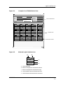
1
®
ETSMIM
Management Module Guide
Notice
Cabletron Systems reserves the right to make changes in specifications and other information
contained in this document without prior notice. The reader should in all cases consult Cabletron
Systems to determine whether any such changes have been made.
The hardware, firmware, or software described in this manual is subject to change without notice.
IN NO EVENT SHALL CABLETRON SYSTEMS BE LIABLE FOR ANY INCIDENTAL,
INDIRECT, SPECIAL, OR CONSEQUENTIAL DAMAGES WHATSOEVER (INCLUDING BUT
NOT LIMITED TO LOST PROFITS) ARISING OUT OF OR RELATED TO THIS MANUAL OR
THE INFORMATION CONTAINED IN IT, EVEN IF CABLETRON SYSTEMS HAS BEEN
ADVISED OF, KNOWN, OR SHOULD HAVE KNOWN, THE POSSIBILITY OF SUCH
DAMAGES.
Virus Disclaimer
Cabletron has tested its software with current virus checking technologies. However, because no
anti-virus system is 100% reliable, we strongly caution you to write protect and then verify that
the Licensed Software, prior to installing it, is virus-free with an anti-virus system in which you
have confidence.
Cabletron Systems makes no representations or warranties to the effect that the Licensed
Software is virus-free.
Copyright © April, 1998, by Cabletron Systems, Inc. All rights reserved.
Printed in the United States of America.
Order Number: 9030981 E5
Cabletron Systems, Inc.
P.O. Box 5005
Rochester, NH 03866-5005
SPECTRUM, the SPECTRUM IMT/VNM logo, DCM, IMT, and VNM are registered
trademarks, and SpectroGRAPH, SpectroSERVER, Inductive Modeling Technology,
Device Communications Manager, and Virtual Network Machine are trademarks of
Cabletron Systems, Inc.
C++ is a trademark of American Telephone and Telegraph, Inc.
UNIX is a trademark of UNIX System Laboratories, Inc.
OSF/Motif and Motif are trademarks of the Open Software Foundation, Inc.
X Window System is a trademark of X Consortium, Inc.
Ethernet is a trademark of Xerox Corporation.
9030981 E5
i
Restricted Rights Notice
(Applicable to licenses to the United States Government only.)
1. Use, duplication, or disclosure by the Government is subject to restrictions as set forth in
subparagraph (c) (1) (ii) of the Rights in Technical Data and Computer Software clause at
DFARS 252.227-7013.
Cabletron Systems, Inc., 35 Industrial Way, Rochester, New Hampshire 03866-5005.
2. (a) This computer software is submitted with restricted rights. It may not be used,
reproduced, or disclosed by the Government except as provided in paragraph (b) of this
Notice or as otherwise expressly stated in the contract.
(b) This computer software may be:
(c)
(1)
Used or copied for use in or with the computer or computers for which it was
acquired, including use at any Government installation to which such computer or
computers may be transferred;
(2)
Used or copied for use in a backup computer if any computer for which it was
acquired is inoperative;
(3)
Reproduced for safekeeping (archives) or backup purposes;
(4)
Modified, adapted, or combined with other computer software, provided that the
modified, combined, or adapted portions of the derivative software incorporating
restricted computer software are made subject to the same restricted rights;
(5)
Disclosed to and reproduced for use by support service contractors in accordance with
subparagraphs (b) (1) through (4) of this clause, provided the Government makes
such disclosure or reproduction subject to these restricted rights; and
(6)
Used or copied for use in or transferred to a replacement computer.
Notwithstanding the foregoing, if this computer software is published copyrighted
computer software, it is licensed to the Government, without disclosure prohibitions, with
the minimum rights set forth in paragraph (b) of this clause.
(d) Any other rights or limitations regarding the use, duplication, or disclosure of this
computer software are to be expressly stated in, or incorporated in, the contract.
(e) This Notice shall be marked on any reproduction of this computer software, in whole or in
part.
ii
ETSMIM
Management Module Guide
Contents
Preface
What is in this Guide ........................................................................................................... ix
Conventions ............................................................................................................................x
Related SPECTRUM Documentation....................................................................................x
Other Related Documentation ...............................................................................................x
Getting Help ......................................................................................................................... xi
Chapter 1
Introduction
What is in this Chapter...................................................................................................... 1-1
ETSMIM Management Module ......................................................................................... 1-1
ETSMIM Applications ........................................................................................................ 1-2
Chapter 2
Device View
What is in this Chapter...................................................................................................... 2-1
Accessing the Device View ................................................................................................. 2-1
Device View ......................................................................................................................... 2-2
Logical Interface Icon ......................................................................................................... 2-2
Ethernet Configuration View/Interface Status........................................................... 2-4
Ethernet Configuration View/Interface Type ............................................................. 2-4
Ethernet Interface Configuration Detail View..................................................... 2-4
Interface Receive Statistics ......................................................................................... 2-5
Interface Send Statistics.............................................................................................. 2-5
Serial Port Logical Interface Icon ...................................................................................... 2-6
Serial Port Configuration View/Interface Status ....................................................... 2-7
Serial Port Configuration View/Interface Type .......................................................... 2-7
Serial Port Performance View ..................................................................................... 2-7
Chapter 3
Configuration View
What is in this Chapter...................................................................................................... 3-1
Accessing the Device Configuration View ......................................................................... 3-1
ETSMIM Device Configuration View ................................................................................ 3-2
Resource and Feature Configuration View ................................................................. 3-3
Resource Utilization Detail View.......................................................................... 3-3
Feature Detail View............................................................................................... 3-4
Ethernet Interface Configuration View ...................................................................... 3-4
9030981 E5
iii
Chapter 3
Configuration View (continued)
Ethernet Interface Configuration Detail View .................................................3-4
Serial Port Configuration View ....................................................................................3-5
Serial Port Configuration Detail View ..................................................................3-5
Basic Port Configuration View ........................................................................3-7
Extended Port Configuration View ...............................................................3-10
Xyplex Server Configuration View.............................................................................3-12
Rotary Table View ................................................................................................3-15
Rotary Detail View ........................................................................................3-15
Parameter Server Configuration View................................................................3-15
SNMP Parameters View ......................................................................................3-16
Get Client Detail View...................................................................................3-17
Set Client Detail View ...................................................................................3-17
Trap Client Detail View ................................................................................3-17
Domain Name Service Parameters View ............................................................3-18
Name Cache Detail View...............................................................................3-18
Queue Parameters View ......................................................................................3-19
Queue Entry Detail View ..............................................................................3-19
ETSMIM Security Configuration View......................................................................3-19
Port Security Table View......................................................................................3-20
Port Security Detail View..............................................................................3-20
Port Login Script Detail View .......................................................................3-21
Kerberos Parameters View ..................................................................................3-22
Script Server Configuration View .......................................................................3-23
Script Server Detail View..............................................................................3-23
Internet Security Configuration View.................................................................3-23
Internet Security Detail View .......................................................................3-24
Telnet Configuration View .........................................................................................3-24
Telnet Port Detail View........................................................................................3-24
LAT Configuration View.............................................................................................3-27
LAT Port Table View ............................................................................................3-28
LAT Port Detail View ....................................................................................3-29
LAT Node Table View...........................................................................................3-29
LAT Node Detail View...................................................................................3-29
LAT Services View ...............................................................................................3-31
LAT Offered Services Detail View ................................................................3-31
Visible Services Detail View..........................................................................3-31
SLIP Configuration View ...........................................................................................3-32
SLIP Configuration Detail View ...................................................................3-32
Chapter 4
Event and Alarm Messages
What is in this Chapter ......................................................................................................4-1
ETSMIM Events and Alarms .............................................................................................4-1
Index
iv
ETSMIM
Management Module Guide
Figures
Chapter 2
Figure 2-1.
Figure 2-2.
Figure 2-3.
Device View
Example of an ETSMIM Device View .................................................................. 2-3
Ethernet Logical Interface Icon ........................................................................... 2-3
Serial Port Logical Interface Icon ........................................................................ 2-6
9030981 E5
v
vi
ETSMIM
Management Module Guide
Tables
Chapter 2
Table 2-1.
Table 2-2.
Chapter 3
Table 3-1.
Table 3-2.
Table 3-3.
Chapter 4
Table 4-1.
Device View
Ethernet Interface Status Label Definitions ....................................................... 2-4
Serial Interface Status Label Definitions ............................................................ 2-7
Configuration View
Input and Output Flow Control Choice Descriptions .......................................... 3-7
Port Default Session Mode Choice Definitions .................................................... 3-9
Source Definitions ............................................................................................... 3-18
Event and Alarm Messages
Events and Alarms ................................................................................................ 4-1
9030981 E5
vii
viii
ETSMIM
Management Module Guide
Preface
Use this guide if you are going to manage an ETSMIM through SPECTRUM.
Before reading this manual, you should be familiar with SPECTRUM’s
functions as described in the Operation documentation and the
Administration documentation. You should also be familiar with any network
management and hardware requirements described in the ETSMIM Terminal
Server documentation.
What is in this Guide
The following chapter descriptions outline the organization of the ETSMIM
Management Module Guide.
Chapter
Description
Chapter 1
Introduction
Describes the ETSMIM management module
and model types.
Chapter 2
Device View
Describes the Device View’s representation
of an ETSMIM, as well as the views and
features available from the Device Menu.
Chapter 3
Configuration Views
Describes the Configuration Views available
for the ETSMIM which provide network
management information for the device.
Chapter 4
Events and Alarms
Contains a listing and explanation of the
event/alarm messages generated in the
Event Log or Alarm View for the ETSMIM
management module.
Chapter 5
Application View
Describes the Application View for the
ETSMIM management module and the
major and minor application information
provided by the view.
9030981 E5
ix
Conventions
Conventions
In this manual, the following conventions are used:
• Command names are printed in bold; for example, Clear or Save &
Close.
• Menu selections to access a view are printed in bold; for example,
Configuration or Detail.
• Buttons are represented by a shadowed box; for example,
Help
Related SPECTRUM Documentation
When using this guide, you should hace a clear understanding of SPECTRUM
functionality and navigation techniques as described in the Administration
documentation, the Operation documentation, and the following
documentation:
SPECTRUM Report Generator User’s Guide
Getting Started with SPECTRUM for Operators
Getting Started with SPECTRUM for Administrators
How to Manage Your Network with SPECTRUM
Other Related Documentation
Refer to the following documentation for more information on managing TCP/
IP-based networks:
LAN Troubleshooting Handbook, Mark Miller (1989, M&T Publishing, Inc.)
The Simple Book — An Introduction to Management of TCP/IP-based
Internets, Marshall T. Rose, Performance Systems International, Inc.
Computer Networks, Andrew S. Tanenbaum, Prentice-Hall, Inc.
Local Area Networks, Architectures and Implementations, James Martin &
Kathleen K. Chapman or the Arben Group, Inc. (1989, Prentice-Hall, Inc.)
Preface
x
ETSMIM
Management Module Guide
Getting Help
Getting Help
For additional support for SPECTRUM products, or to make comments or
suggestions regarding SPECTRUM or this manual, contact Cabletron
Systems Technical Support via one of the following means:
Location
Mail
FAX
Telephone
603-337-3075
603-337-3500
(*)-44-635-552062
(*)-44-635-580000
Europe
Cabletron Systems, Ltd.
Network House
Newbury Business Park
London Road, Newbury
Berkshire, England RG13 2PZ
E-mail: [email protected]
(*)-61-2-950-5950
(*)-61-2-950-5900
Pacific
Cabletron Systems, Inc.
Allambie Grove Estate
25 French’s Forest Road East
French’s Forest, NSW 2086
Sydney, Australia
E-mail: [email protected]
(*)-81-3-3240-1985
(*)-81-3-3240-1981
Japan
Cabletron Systems, KK
JTB Building 9F
164 Maranouchi
Chiyoda-ku
Tokyo 100 Japan
E-mail: [email protected]
(*)-65-7763382
(*)-65-7755355
Singapore
Cabletron Systems, Inc.
85 Science Park Drive
#03-03/04
The Cavendish
Singapore 051
E-mail: [email protected]
(*)-49-6103/991-229
(*)-49-6103/991-269
Germany
Cabletron Systems GmbH
Dreieich Park
Im Gefierth 13d
63303 Dreieich
Frankfurt, Germany
E-mail: [email protected]
Cabletron Systems, Inc.
P. O. Box 5005
North America
Rochester, NH 03866-5005
E-mail: [email protected]
*International Operator Code
Questions About SPECTRUM Documentation?
E-MAIL
9030981 E5
Send your questions, comments or suggestions regarding SPECTRUM
documentation to the Technical Communications Department directly via the
following internet address:
[email protected]
Preface
xi
Getting Help
Preface
xii
ETSMIM
Management Module Guide
Chapter 1
Introduction
What is in this Chapter
This chapter describes the SPECTRUM Management Module for the
ETSMIM. It also provides the model type names assigned to the ETSMIM in
SPECTRUM. The model type name refers to the template used to specify
attributes, actions, and associations for device models in SPECTRUM.
ETSMIM Management Module
The ETSMIM Management Module manages ETSMIM devices using the
SNMP network management agent and the Management Information Bases
(MIBs), included with the management module.
9030981 E5
1-1
ETSMIM Applications
ETSMIM Applications
The ETSMIM supports common and device-specific applications. These
applications are described in the Bridging Applications Reference, the MIB II
Applications Reference, or the Miscellaneous Applications Reference, and are
as follows:
• MIB-II (SNMP2_Agent)
- IP (IP2_App)
- System (System2_App)
- ICMP (ICMP_App)
- UDP (UDP2_App)
• Ethernet App
- Ethernet IF App
RMON and DLM are also supported and SPECTRUM management of these
MIBs may be purchased separately. Refer to the documentation provided with
the RMON and DLM management modules for descriptions of these
capabilities. The following chapters explain how to use SPECTRUM and the
management module software to monitor and manage an ETSMIM.
Introduction
1-2
ETSMIM
Management Module Guide
Chapter 2
Device View
What is in this Chapter
The Device View for the ETSMIM allows you to view the logical
representations of the ETSMIM device and ports. The Device View also
provides you with menu bar access to views that monitor and control the
ETSMIM’s performance and its ports.
Accessing the Device View
Access the Device view using one of the following methods.
• Double-click on the Device view button of the ETSMIM device icon.
Device View Button
9030981 E5
2-1
Device View
• Highlight the ETSMIM device icon and select Device from the Icon
Subviews menu.
Go Back
Go Up
Icon Subviews
View Path
New View
Bookmarks
View History
Current View Info...
Notes...
Jump by name...
Zoom
Map Hierarchy
Close
Navigate
Alarms
Performance
Notes...
Utilities
Zoom
Device
DevTop
Device View
The Device view provides a logical representation of the terminal server’s
Ethernet and serial interfaces. The interface icons represent each port on the
ETSMIM. Figure 2-1 provides and example of an ETSMIM Device view.
Logical Interface Icon
The Logical Interface icon consists of five zones, providing configuration and
performance information. Figure 2-2 provides a detailed illustration of the
Ethernet Port Logical Interface Icon and the following sections detail each
icon zone.
Device View
2-2
ETSMIM
Management Module Guide
Logical Interface Icon
Figure 2-1.
Example of an ETSMIM Device View
Primary Landscape 0x00400000 - VNM Host - of type Xyp_ETSMIM
*
File
View
Help?
Net Addr
Model Name
Sys Up Time
Contact
Manufacturer
Description
Device Type
Location
Serial Number
Prime-App
1
ON
Enet
Rx 107
Tx 1116
1
ON
Rs423
5
ON
Rs423
In 0
Out 0
6
ON
Rs423
10
ON
Rs423
11 ON
Rs423
In 0
Out 0
Figure 2-2.
In 0
Out0
In 0
Out0
In 0
Out0
Device View Banner
2
ON
Rs423
In 0
Out 0
3
ON
Rs423
In 0
Out 0
4
ON
Rs423
In 0
Out 0
7
ON
Rs423
In 0
Out 0
8
ON
Rs423
In 0
Out 0
9
ON
Rs423
In 0
Out 0
12
ON
Rs423
In 0
Out 0
13
ON
Rs423
In 0
Out 0
14
ON
Rs423
In 0
Out 0
Interface Icons
Interface Icon Panel
Ethernet Logical Interface Icon
(a)
(b)
1
ON
Enet
(c)
Rx 107
(d)
Tx 1116
(e)
a. Interface Number
b. Ethernet Configuration view/Interface Status
c. Ethernet Configuration view/Interface Type
d. Interface Receive Statistics/Packets Received
e. Interface Send Statistics/Packets Transmitted
9030981 E5
Device View
2-3
Logical Interface Icon
Ethernet Configuration View/Interface Status
Ethernet Configuration View/Interface Status
The Ethernet Interface Configuration view label displays a textual and
background color representation of the current status of the interface. Doubleclicking on this label accesses the Interface Status view. Table 2-1 displays
interface status options and their respective colors.
Table 2-1.
Ethernet Interface Status Label Definitions
Operational
Status
Administrative
Status
Text Display
Color
ON
ON
ON
Green
OFF
OFF
OFF
Yellow
OFF
ON
OFF
Yellow
TEST
TEST
TEST
Yellow
Ethernet Configuration View/Interface Type
Double-clicking on this label accesses the Ethernet Interface Configuration
Detail view.
Ethernet Interface Configuration Detail View
The Ethernet Interface Configuration view provides the following information
for the ETSMIM’s Ethernet interfaces:
Operational Status
The current operational state of the port (ON, OFF, or TEST).
Administrative Status
This field provides a button that allows you to choose the desired operational
state of the port (ON, OFF, or TEST).
Last Status Change
The System UpTime value when the port entered its current operational
state.
Physical Address
The Ethernet (MAC) address of the port.
Bandwidth
The estimated bandwidth of the interface measured in bits per second. For
interfaces that do not vary in bandwidth or for which no accurate estimate can
be made, a nominal bandwidth is provided.
Device View
2-4
ETSMIM
Management Module Guide
Logical Interface Icon
Interface Receive Statistics
Largest Datagram Supported
The largest Maximum Transmission Unit (MTU), measured in octets, that can
be transmitted or received by the port.
Length of Output Packet Queue
The length of the outbound packet queue in packets.
Interface Receive Statistics
The Interface Receive Statistics view is accessed by double-clicking on the
Receive Statistics label or by highlighting the Ethernet Logical Interface icon
and selecting Receive Statistics from the Icon Subviews menu. The
Interface Receive Statistics view provides the following information on
incoming port traffic:
Unknown Protocol Packets Received
The number of packets discarded because of an unknown protocol.
Unicast Packets Delivered
The number of unicast packets delivered to a higher level protocol.
NonUnicast Packets Delivered
The number of non-unicast packets delivered to a higher level protocol.
Inbound Packets Discarded
The number of inbound packets discarded even though no errors were
detected to make them undeliverable. Such packets may have been discarded
to increase buffer space.
Inbound Errors
The number of packets containing errors preventing them from being
delivered to a higher level protocol.
In addition, the Interface Receive Statistics view contains a gauge which
measures the total number of octets received by the port. An Octets
Received button accesses a rate graph displaying the total number of octets
received by the port over a given timeframe.
Interface Send Statistics
The Interface Send Statistics view is accessed by double-clicking on the Send
Statistics label or by highlighting the Ethernet Logical Interface icon and
selecting Send Statistics from the Icon Subviews menu. The Interface Send
Statistics view provides the following information on outgoing port traffic:
Outbound Packet Queue
The length of the outbound packet queue in packets.
9030981 E5
Device View
2-5
Serial Port Logical Interface Icon
Unicast Packets Requested
The number of unicast packets that a higher level protocol requested for
transmission.
NonUnicast Packets Requested
The number of non-unicast packets that a higher level protocol requested for
transmission.
Outbound Packets Discarded
The number of outbound packets discarded even though no errors were
detected to prevent them from being transmitted. Such packets may have
been discarded to increase buffer space.
Outbound Errors
The number of packets containing errors preventing them from being
transmitted to a higher level protocol.
In addition, the Interface Send Statistics view contains a gauge which
measures the total number of octets transmitted by the port. An Octets Sent
button accesses a rate graph displaying the total number of octets transmitted
by the port over a given timeframe.
Serial Port Logical Interface Icon
The Serial Port Logical Interface icon consists of five zones, providing
configuration and performance information. Figure 2-3 provides a detailed
illustration of the Serial Port Logical Interface icon and the following sections
detail each icon zone.
Figure 2-3.
Serial Port Logical Interface Icon
(a)
(b)
1
ON
Rs423
(c)
In 0
(d)
Out 0
(e)
a. Interface Number
b. Serial Port Configuration View/Interface Status
c. Serial Port Configuration View/Interface Type
d. Serial Port Performance View/Characters In
e. Serial Port Performance View/Characters Out
Device View
2-6
ETSMIM
Management Module Guide
Serial Port Logical Interface Icon
Serial Port Configuration View/Interface Status
Serial Port Configuration View/Interface Status
The Serial Port Configuration view label displays a textual and background
color representation of the current status of the interface. Double-clicking on
this label accesses the Interface Status view. Table 2-2 displays the interface
status options and their respective colors.
Table 2-2.
Serial Interface Status Label Definitions
Operational
Status
Administrative
Status
Text Display
Color
ON
ON
ON
Green
OFF
OFF
OFF
Yellow
OFF
ON
OFF
Yellow
MAINTENANCE
MAINTENANCE
TEST
Yellow
Serial Port Configuration View/Interface Type
The Serial Port Configuration Detail view is accessed by double-clicking on
the Serial Port Configuration View/Interface Type label or by highlighting the
Serial Port Logical Interface icon and selecting Serial Port Configuration
from the Icon Subviews menu. The Serial Port Configuration Detail view is
described in Chapter 3, Configuration View.
Serial Port Performance View
The Serial Port Performance Detail view is accessed by double-clicking on the
Serial Port Performance view label (Characters In and Characters Out access
the same view) or by highlighting the Serial Port Logical Interface icon and
selecting Serial Port Performance from the Icon Subviews menu.
9030981 E5
Device View
2-7
Serial Port Logical Interface Icon
Serial Port Performance View
Device View
2-8
ETSMIM
Management Module Guide
Chapter 3
Configuration View
What is in this Chapter
This chapter provides general descriptions of the configuration views that are
available for the ETSMIM. These views allow you to access device-specific
configuration information.
Accessing the Device Configuration View
Access the Device Configuration view using one of the following methods:
• Double-click on the Device Configuration view label of the ETSMIM device
icon.
Device Configuration View Label
9030981 E5
3-1
ETSMIM Device Configuration View
• Highlight the ETSMIM device icon and select Configuration from the
Icon Subviews menu.
Go Back
Go Up
Icon Subviews
View Path
New View
Bookmarks
View History
Current View Info...
Notes...
Jump by name...
Zoom
Map Hierarchy
Device
DevTop
Application
Acknowledge
Flash Green Enabled
Configuration
Model Information
Primary Application
ETSMIM Device Configuration View
The Device Configuration View provides information on the configuration of
the ETSMIM and allows you to modify the values of some fields. This view
provides the following information:
Server Ident
A text message identifying the terminal server. You can modify this field.
Server Name
The node name of the terminal server. You can modify this field.
Load File
The software file name to request for down-line load of the terminal server.
You can modify this field.
Load Host
The internet address of the terminal server from which to load an image via
TFTP (Trivial File Transfer Protocol).
Load Address
The IP address of the host from which the terminal server was last loaded.
Configuration View
3-2
ETSMIM
Management Module Guide
ETSMIM Device Configuration View
Resource and Feature Configuration View
Dump Address
The IP address of the node that received the last terminal server memory
dump.
Resources
The number of times a local resource allocation failed, for example, due to lack
of dynamic memory.
Features
The number of feature entries in the Feature table.
SW Type
The software version variant running in the terminal server.
SW Rev
The software version running in the terminal server. In order, the octets
contain major version, minor version, ECO, and pre-release number.
HW Type
The hardware type on which the terminal server is running.
HW Rev
The hardware version on which the terminal server is running.
ROM Rev
The firmware version of the bootstrap ROM installed in the terminal server.
Chassis Type (Mx45xx)
The type of chassis in which the terminal server is running.
Ethernet Interfaces
A unique value for each interface.
Serial Ports
The number of basic character serial ports available.
Resource and Feature Configuration View
You access this view by clicking on the Resource & Feature Detail Button in
the ETSMIM Configuration view. This view contains entries in a Resource
Utilization panel and a Features panel. To modify the maximum allowed
usage, double-click on any entry in the Resource Utilization panel and the
Resource Utilization Detail view appears with detailed information for the
selected resource. To alter the status of a feature, double-click on any entry in
the Features panel and the Feature Detail view appears with the same
information in a modifiable format for the selected feature. Fields for both
detail views are presented below.
9030981 E5
Configuration View
3-3
ETSMIM Device Configuration View
Ethernet Interface Configuration View
Resource Utilization Detail View
Resource
The percentage of processing time that the terminal server has used
(calculated every second).
Current Usage
The number of resources currently in use on the terminal server.
Highest Usage
The current maximum possible number of resources in the terminal server.
Max. Allowed Usage
The maximum possible number of resources in the terminal server. You can
modify this value.
Exceeded Supply
The number of times since system initialization that the system could not
obtain the resource because none were available.
Feature Detail View
Feature
A list of feature entries.
Status
This field provides a button that allows you to enable or disable the feature for
the next system initialization.
Ethernet Interface Configuration View
You access this view by clicking on the Ethernet Interfaces Detail Button in
the ETSMIM Configuration view. This view contains entries in an Ethernet
Configuration table. Double-click on any entry in the table to access the
Ethernet Interface Configuration Detail view for the selected entry with
detailed information. Fields for the detail view are presented below.
Ethernet Interface
The interface identified by a particular value. The default is 1.
Description
A description of the interface.
Type
The type of interface.
Configuration View
3-4
ETSMIM
Management Module Guide
ETSMIM Device Configuration View
Serial Port Configuration View
Ethernet Interface Configuration Detail View
Operational Status
The current operational state of the port as either up, down, or testing. You
can modify this field.
Administrative Status
This field provides a button that allows you to set the desired operational
state of the port.
Last Status Change
The system uptime that the port entered its current operational state.
Physical Address
The Ethernet (MAC) address of the port.
Bandwidth
The estimated bandwidth of the interface measured in bits per second. For
interfaces that do not vary in bandwidth or for which no accurate estimate can
be made, a nominal bandwidth is provided.
Largest Datagram Supported
The largest Maximum Transmission Unit (MTU), measured in octets, that can
be transmitted or received by the port.
Length of Output Packet Queue
The length of the outbound packet queue in packets.
Serial Port Configuration View
You can access this view by clicking on the Serial Ports Detail Button in the
ETSMIM Configuration view. This view contains entries in a Serial Port
Configuration table. Double-click on any entry in the table to access the Serial
Port Configuration Detail view for the selected entry with more detailed
information in a modifiable format.
Serial Ports
The number of ports the device supports (defaults to 16).
Serial Port Configuration Table
This table includes the following fields described below: Type, Speed, Bits,
Stopbits, Parity, In Flow Control, and Out Flow Control. Double-clicking on
any entry accesses the Serial Port Configuration Detail View for that entry.
Fields for the detail view are presented below.
9030981 E5
Configuration View
3-5
ETSMIM Device Configuration View
Serial Port Configuration View
Serial Port Configuration Detail View
Port
A value uniquely identifying a port.
Port Name
Refers to an alphanumeric identifier for a port. You can modify this field.
Port Type
The type of terminal attached to the port for formatting local output.
Input Speed
The port’s input speed in bits per second. You can modify this field.
Output Speed
The port’s output speed in bits per second. You can modify this field.
Autobaud
This field provides a button that allows you to enable or disable the port’s
ability to automatically sense input speed.
Parity
This field provides a button that allows you to choose the port’s sense of a
character parity bit as either none, odd, even, mark, or space.
Bits
The number of bits in a character. The default is 8. You can modify this field.
Stop Bits
This field provides a button that allows you to choose the number of stop bits.
The choices are 1.0, 2.0, 1.5, or dynamic.
Input Signals
The number of input signals for the port in the input signal table. The table
contains entries only for those signals the software can detect.
Output Signals
The number of output signals for the port in the output signal table. The table
contains entries only for those signals the software can verify.
Admin Status
This field provides a button that allows you to choose the desired port state,
independent of flow control. On indicates that the port is allowed to pass
characters and form new sessions. Disabled indicates that the port is allowed
to pass characters but not form new sessions. Off indicates that the port is not
allowed to pass characters or have any sessions. Maintenance indicates a
maintenance mode, exclusive of normal operation (e.g., running a test).
Opr Status
The port’s actual operational state, independent of flow control. On indicates
that the port is able to function normally. Off indicates the port’s inability to
function for administrative or operational reasons. Maintenance indicates a
maintenance mode, exclusive of normal operation (e.g., running a test). Absent
Configuration View
3-6
ETSMIM
Management Module Guide
ETSMIM Device Configuration View
Serial Port Configuration View
indicates that port hardware is not present. Active indicates that the port is
on with a user present (e.g., logged in).
Input FlowCtrl
This field provides a button that allows you to choose the type of input flow
control. The choices for data flow control are described in Table 3-1.
Table 3-1.
Input and Output Flow Control Choice Descriptions
Flow
Control
Description
XonXoff
Software flow control by recognizing Xon and Xoff characters.
Hardware
Flow control delegated to the lower level (i.e., a parallel port).
CtsRts
Clear to Send and Request to Send. Specific to RS-232-like ports.
DtsDtr
Data Terminal Send and Data Terminal Ready. Specific to RS-232like ports.
None
No flow control at this level or below.
Output FlowCtrl
This field provides a button that allows you to choose the type of output flow
control. Refer to Table 3-1 for the descriptions of data flow control options.
Reset
This field provides a button that allows you to execute a reset of the port into a
clean, initial state, for both hardware and software, disconnecting all of the
port’s existing sessions.
Admin Origin
This field provides a button that allows you to choose the administrative
origin of the port to device connection. Dynamic indicates that the port is
accessible from either the local command mode, or remotely by service name
or port number. Local indicates that the port is accessible only from the local
command mode. Remote indicates that the port is accessible remotely by
service name or port number. None indicates that the port is not accessible
and the server prevents any use of the port.
Maximum Sessions
The maximum number of sessions. The default is 4. You can modify this field.
9030981 E5
Configuration View
3-7
ETSMIM Device Configuration View
Current Sessions
The number of sessions currently open.
Basic Configuration
Clicking on this button accesses the Basic Port Configuration view.
Extended Configuration
Clicking on this button accesses the Extended Port Configuration view.
Basic Port Configuration View
Port
A value that uniquely identifies the port.
Port Status
The current operational status of the port.
Active Username
The user name currently logged into the port.
Last Character Input
The most recent character received into the port.
Last Character Output
The most recent character transmitted from the port.
Local Accesses
The number of times a user has logged on to the port, since the counter was
reset to zero.
Idle Timeouts
The number of times that the terminal server has disconnected a session
initiated by the remote connection queue for being inactive, since the counter
was reset to zero.
Port Remote Sessions
The number of remote sessions to the port since terminal server initialization.
Zero Port Counters
This field provides a button that allows you to zero counters for the port.
Selecting execute causes the port’s counters to be zeroed, selecting ready has
no effect.
Default Username
The default user name for automatically logging into the port. You can modify
this field.
Configuration View
3-8
ETSMIM
Management Module Guide
ETSMIM Device Configuration View
Default Protocol
This field provides a button that allows you to choose which protocol to use
with Default Name. The choices are LAT (Local Access Terminal), telnet, or
any.
Default Action
This field provides a button that allows you to choose the action to take
relative to Default Name. The choices are Preferred (preferred service) or
Dedicated (port dedicated).
Default LAT Port Name
A LAT port name to use with Default Name may be entered.
Default LAT Node Name
A LAT node name to use with Default Name may be entered.
Default Name
The default user name for automatically logging into the port may be entered.
Port Autologin
This field provides a button that allows you to enable or disable automatic
port login.
Port Autoconnect
This field provides a button that allows you to enable or disable automatic
session connection.
Port Connectresume
This field provides a button that allows you to control connection attempts to a
destination where the port already has a connection. When enabled, the
existing connection becomes the active connection. When disabled, a new
connection will be created.
Port Multisessions
This field provides a button that allows you to enable or disable the
multisession line protocol between the port and the locally-connected
terminal.
Port Broadcast
This field provides a button that allows you to enable or disable broadcast
messages from this port to other local ports.
Port Dialup
This field provides a button that allows you to enable or disable connection to
a dialup line.
Port Default Session Mode
This field provides a button that allows you to choose the data recognition
mode used when starting a session. Table 3-2 describes the choices.
9030981 E5
Configuration View
3-9
ETSMIM Device Configuration View
Table 3-2.
Port Default Session Mode Choice Definitions
Mode
Definition
Interactive
Locally recognizes all controls.
Binary
Recognizes only session protocol.
XonXoff
Recognizes only Xon and Xoff.
Transparent
Recognizes no data.
Port Message Codes
This field provides a button that allows you to enable or disable the inclusion
of error numbers in the error messages displayed on the port.
Port Verification
This field provides a button that allows you to enable or disable the display of
informational messages on the port when the user connects, disconnects, or
switches a session.
Port Loss Notification
This field provides a button that allows you to enable the sending of a Bell
character to the port when it loses an input character due to an overrun or
data error.
Port Inactivity Logout
This field provides a button that allows you to enable or disable an automatic
port logout if activity has not occurred within the specified idle timeout period.
Port Queuing
This field provides a button that allows you to enable or disable the queueing
of requests for using the port.
Port Idle Timeout
You may enter the time in minutes a session may have no activity before it is
automatically disconnected. A value of -1 indicates no timeout. Zero is not
valid.
Extended Port Configuration View
All of the following fields, except for Port, are modifiable:
Port
A value uniquely identifying the port.
Terminal Type
The type of terminal attached to the port for formatting local output. The
options are ANSI, Hardcopy, or Softcopy.
Configuration View
3-10
ETSMIM
Management Module Guide
ETSMIM Device Configuration View
Prompt
The prompt for the system to use on the port.
Backwards Switch
The character input from the character port to cause a switch to the previous,
lower numbered session.
Forwards Switch
The character input from the character port to cause a switch to the next,
higher numbered session.
DCD Timeout
The time, in milliseconds, that DCD (data carrier detect) may be asserted
before disconnecting the port.
Typeahead Size
The maximum number of input characters to hold pending transmission on a
session.
Line Editor
This field provides a button that allows you to enable or disable the user from
using local mode command line editing.
Begin Line Character
Character input from the character port to move the cursor to the beginning of
the line.
End of Line Character
Character input from the character port to move the cursor to the end of the
line.
Cancel Character
Character input from the character port to cancel an interactive dialog or
delete the current line.
Quoting Character
Character input from the character port to inhibit interpretation of the next
input character.
Forwards Character
Character input from the character port to move the cursor to the right.
Del Begin Character
Character input from the character port to delete the current line from the
cursor to the beginning.
Previous Line Character
Character input from the character port to recall the previous, older line in
the command history.
Next Line Character
Character input from the character port to recall the next, newer line in the
command history.
9030981 E5
Configuration View
3-11
ETSMIM Device Configuration View
Resolve Service
This field provides a button that allows you to choose the session protocol to
use when not otherwise specified: LAT, Telnet, or Any.
DTR Wait
This field provides a button that allows you to determine when the system
sends a DTR (data terminal ready) signal on the port. DTR can be configured
so that a notification is made: at all times (Always), when a connection or a
ring has been established (ConnectOrRing), when a connection has been
established (ConnectOnly), or when a ring has been established (RingOnly).
DSR Logout
This field provides a button that allows you to enable or disable logging out
the port when DCD (data carrier detect) is no longer in effect.
Signal Check
This field provides a button that allows you to enable or disable observing
DSR (data set ready) and DCD (data carrier detect) to bound allowing
sessions.
Interrupts
This field provides a button that allows you to permit recognition of the
BREAK or local switch key to interrupt a session.
Modem Control
This field provides a button that allows you to enable or disable the
observation of hardware modem control signals.
Pause
This field provides a button that allows you to pause local-output to the port
after each screenfull.
Break
This field provides a button that allows you to choose the action taken on a
BREAK condition from the port. The options are Ignore, suspend the current
session and switch to a local command prompt (LocalSwitch), or notify a
remote device (SendRemote).
Internet Connections
This field provides a button that allows you to enable outgoing connection by
internet address. When disabled, connections are requested by domain name.
Window Size
You may enter the size of the TCP window for TCP connections on the port.
Dialback
This field provides a button that allows you to enable or disable the use of
dialback when a user logs in on the port. The dialback feature is used in
conjunction with a script server that runs a script to reset the line and dial a
stored phone number.
Dialback Timeout
The time, in seconds, to wait for remote modem response when dialing back.
Configuration View
3-12
ETSMIM
Management Module Guide
ETSMIM Device Configuration View
Xyplex Server Configuration View
Xyplex Server Configuration View
Access this view by clicking on the Server Button in the ETSMIM
Configuration view.
Server Date
The system’s current local date and time.
Server Timezone
The adjustment to apply to a universal (Greenwich) time received when downline loaded. The adjustment is represented by two octets; the first octet is the
number of hours west of universal, the second is the number of minutes.
Server Welcome
The text string the server displays before attempting to log in a user.
Server Login Prompt
The text string the server displays to prompt a user for the login password.
Sessions Limit
The maximum number of service nodes to keep in the node table.
Inactivity Timer
The amount of time, in minutes, that a port can remain logged in to the server
and have no connected sessions before the port is logged off.
Rotary Table Entries
The parameter values for a rotary. A rotary refers to the assignment of the
same internet address or domain name to multiple destinations that offer the
same type of service.
Detail
Click on this button to access to the Rotary Table View described later in this
section.
Primary Gateway Addr
The internet address of the system’s primary (first choice) gateway. A value of
0.0.0.0 indicates no address.
Secondary Gateway Addr
The internet address of the system’s secondary (second choice) gateway. A
value of 0.0.0.0 indicates no address.
Subnet Mask Autoconfigure
This field provides a button that allows you to enable automatic
determination of the internet subnet mask by the server. If disabled, an
internet subnet mask specified by the server manager is used.
Fragment Reassembly
This field provides a button that allows you to enable the reassembly of IP
fragments.
9030981 E5
Configuration View
3-13
ETSMIM Device Configuration View
Server Broadcast
This field provides a button that allows you to enable the server to broadcast
it’s IP address used in internet broadcast messages.
Server Change
This field provides a button that allows you to choose the system’s operation
with regard to DEFINE commands. The two options are permOnly, which
indicates that commands modify only the permanent database, and
OperAndPerm which indicates that commands modify both operational and
permanent databases.
Server Dump
This field provides a button that allows you to enable the dumping of the
system’s memory when the system crashes.
Server Report Errors
This field provides a button that allows you to enable the server to display an
error when the user gives an unsupported command.
Server Console Logout
This field provides a button that allows you to enable automatic disconnection
of a session when a console port user logs out.
Active Users
The number of ports that have interactive sessions connected.
High
The highest value of active users since system initialization.
Active Ports
The number of ports that have interactive sessions or remote-access
connections.
High
The highest value of active ports since system initialization.
Connected Sessions
The total number of sessions which the server has connected.
High
The highest value of sessions since system initialization.
Zero All
This field provides a button that allows you to zero counters for the system.
Selecting execute causes all of the system’s counters to be zeroed, selecting
ready has no effect.
Last
The time, in seconds, when all of the counters were last set to zero.
Zero Base
This field provides a button that allows you to zero all the system’s base
counters. Selecting execute causes all of the system’s base counters to be
zeroed, selecting ready has no effect. The SNMP counter is an example of a
Configuration View
3-14
ETSMIM
Management Module Guide
ETSMIM Device Configuration View
counter that may be zeroed. Examples of counters not zeroed are Ethernet
interface counters or port counters.
Initialize
This field provides a button that allows you to choose how the system resets
its software to initial load values, usually by reloading. If conditional
execution is selected, the initialization takes place only if the overall system
state is acceptable (e.g., when there is no need to store permanent
parameters). If unconditional execution is selected, the initialization takes
place regardless of the overall system state. Cancel aborts an initialization
that has not yet started.
Delay
The number of minutes to delay before beginning the system initialization
process. The default value is 1.
Crash
This field provides a button that allows you to reboot.
Parameter Server
Click on this button for access to the Parameter Server Configuration view.
SNMP Parameters
Click on this button for access to the SNMP Parameters view.
DNS Parameters
Click on this button for access to the Domain Name Server Parameters view.
Queue Parameters
Click on this button to access the Queue Parameters view.
Rotary Table View
This window displays the rotary table. Double-click on any entry within the
table to access the Rotary Detail view for that entry. The detail view provides
more detailed information than the Rotary Table view. These fields are
described below.
Rotary Detail View
Status
The status of this entry. Setting the value to Invalid invalidates the entry.
9030981 E5
Configuration View
3-15
ETSMIM Device Configuration View
Address
The internet address to be recognized as a rotary address.
Port Map
The list of character ports that compose the rotary. The value for this field
contains a bitmap, with one bit for each port, and enough octets for all the
ports on the system.
Parameter Server Configuration View
Loaded From
The name of the system that most recently provided the terminal server’s
stored parameters.
MAC Address
The Ethernet address contained in the Client Loader Address.
Version Last Loaded
The network address of the system that most recently provided the system’s
stored parameters.
Known Parameter Servers
The number of parameter servers known to this system, indicating the
number of entries in the server table.
Max
The maximum number of attempts by this system to store new parameters
with a server that has not acknowledged previous attempts. You can modify
this field.
Perform Immediate Search
Selecting execute with this button causes this system to immediately check for
additional parameter servers. Selecting Ready has no effect.
Periodic Search
This field provides a button that allows you to enable or disable the periodic
search for additional parameter servers.
Search Interval
The number of minutes between checks for additional parameter servers. You
can modify this field.
Retransmit Timer
The number of minutes between the system’s attempts to store new
parameters with a server that has not acknowledged previous attempts. You
can modify this field.
Retransmit Limit
The maximum number of times the server will attempt to retransmit a
message that has not been acknowledged by a service node. You can modify
this field.
Configuration View
3-16
ETSMIM
Management Module Guide
ETSMIM Device Configuration View
Bad Parameter Messages
The number of invalid parameter service protocol messages received by the
system.
Rejected Servers
The number of parameter servers the system rejected due to exceeding the
client server limit.
SNMP Parameters View
This window displays three tables: Get Client Detail Table, Set Client Table,
and Trap Client Table. Double-click on any entry within a table and the detail
view for that entry appears. The detail views include the same information as
that presented in the tables in a modifiable format. These fields are described
below.
Get PDU Community String
The SNMP community name allowed to perform get-requests or get-next
requests. You can modify this field.
Set PDU Community String
The SNMP community name allowed to perform set-requests. You can modify
this field.
Trap PDU Community String
The SNMP community name sent in traps from this agent. You can modify
this field.
Get Client Detail View
Entry
The parameter values for a get client.
Entry Status
This field provides a button that allows you to choose the status of this entry.
Possible choices are Invalid or Valid.
IP Address
The client’s network address. You can modify this field.
Set Client Detail View
Entry
Provides a list of set client entries.
9030981 E5
Configuration View
3-17
ETSMIM Device Configuration View
Entry Status
This field provides a button that allows you to choose the status of this entry.
Possible choices are Invalid or Valid.
IP Address
The client’s network address. You can modify this field.
Trap Client Detail View
Entry
The parameter values for a trap client.
Entry Status
This field provides a button that allows you to choose the status of this entry.
Possible choices are Invalid or Valid.
IP Address
The client’s network address. You can modify this field.
Domain Name Service Parameters View
This window includes the Name Cache Panel as well as the information below.
Double-click on any entry within the table to access the detail view for that
entry. The detail view allows you to modify some of the information presented
in the table. Following are the field descriptions:
Domain Name Suffix
The domain name for the terminal server on the network.
Secondary Domain Address
The IP address at which a domain name server is located. The terminal server
can use up to two domain name servers - primary and secondary.
Primary Domain Address
The IP address at which a domain name server is located. The terminal server
can use up to two domain name servers - primary and secondary.
Domain TTL
The number of hours that a domain name will be retained by the server.
Name Cache Entries
The number of entries in the name cache table.
Configuration View
3-18
ETSMIM
Management Module Guide
ETSMIM Device Configuration View
Name Cache Detail View
Status
This field provides a button that allows you to choose the status of the entry.
When set to Invalid, the entry is removed from the table.
Domain Name
A fully qualified domain name.
IP Address
The internet address corresponding to the domain name.
Source
Defines the creator of the entry. Possible sources are defined in Table 3-3.
Table 3-3.
Source Definitions
Source
Definition
Local
Defined by manager.
Primary
Obtained from primary name server.
Secondary
Obtained from secondary name server.
TTL
The number of minutes remaining in the entry’s Time-to-Live.
Queue Parameters View
This window displays the Queue Table as well as the information below.
Double-click on any entry within the table to access the detail view for that
entry. The detail view includes more detailed information than the table and
allows some modification. Following are the field descriptions:
Queue Limit
The maximum number of entries that can be made in the Queue table. You
can modify this field.
Queue Entries
The number of connection requests queued in the server connection queue.
High
The greatest number of entries in the Queue table since system initialization.
9030981 E5
Configuration View
3-19
ETSMIM Device Configuration View
ETSMIM Security Configuration View
Queue Entry Detail View
Entry
The job number of a queued request.
Status
This field provides a button that allows you to choose the status of a queue
entry. To remove an entry set to invalid.
SourceNode
The name of the system that originated the queue entry.
Service
The name of the service for which the originator is waiting.
Port
The number of the port for which the originator is waiting, if supplied by the
originator.
Port Name
The name of the port for which the originator is waiting, if supplied by the
originator.
ETSMIM Security Configuration View
Server Login Password
The password a user must enter to be given the opportunity to log in. You can
modify this field.
Server Privileged Password
The password a user must enter to become a privileged user. You can modify
this field.
Server Maintenance Password
The password a management system must supply to force the system to
reboot or use the system’s remote console using the Maintenance Operation
Protocol (MOP). When setting this value, fill with zeros from the first octet.
That is, the value ‘1ab42’ is expressed as ‘0.0.0.0.0.1.ab.42’. A value of zero
disables the password check. You can modify this field.
Server Lock
This field provides a button that allows you to enable or disable the server
lock.
Server Password Limit
The maximum number of service nodes the server can retain information
about. You can modify this field.
Maximum Number of Entries
The number of times the server allows a user to retry an incorrect password.
Configuration View
3-20
ETSMIM
Management Module Guide
ETSMIM Device Configuration View
Internet Security Entries
The number of valid security entries in the system’s port security table.
Port Security Table
Select this button to view the Port Security Table view.
Kerberos
Select this button to view the Kerberos Parameters view.
Script Servers
Select this button to view the Script Server Configuration view.
Internet Security Table
Select this button to view the Internet Security Configuration view.
Port Security Table View
This window displays the Port Security Table. Double-click on any entry
within the table to access the detail view for that entry. The detail view
includes more detailed information than the panel in a modifiable format.
Following are the field descriptions:
Port Security Detail View
Port
A value that uniquely identifies the port.
Inbound Access
This field provides a button that enables you to allow or deny access to the
port of incoming TCP connections.
Outbound Access
This field provides a button that enables you to allow or deny access to the
port of outgoing TCP connections.
Password
This field provides a button that allows you to enable or disable the
requirement for a login password to log in on the port.
Limited Commands
This field provides a button that allows you to enable or disable the commands
available to the user on the port.
9030981 E5
Configuration View
3-21
ETSMIM Device Configuration View
Limited View
This field provides a button that allows you to enable or disable what a user
may display.
Kerberos Status
This field provides a button that allows you to set the level of Kerberos
operation on the system as either none or login.
Port Login Script Detail View
This view is available from the Port Security Table by double-clicking on the
desired entry in the Log Script column.
Port
A value that uniquely identifies the port.
Login Script
This field provides a button that allows you to enable, disable, or require the
script action taken when a user logs in on the port.
Loader Address
The network address of the server that provided the script for the current port
login.
Script Filename
The path and file name of the script used for the current port login.
Script Echo
This field provides a button that allows you to enable or disable the display of
script operation on the port when running a script.
Kerberos Parameters View
Kerberos
This field provides a button that allows you to require the entry of a login or
Kerberos password for the use of the port.
Realm
The Kerberos realm with which the Server Name 1 and Server Name 2 are
associated. You can modify this field.
Query Limit
The maximum number of attempts the system can make when trying to verify
a Kerberos ID. You can modify this field.
Master
The domain name of the Kerberos master host system, which holds the
Kerberos database. You can modify this field.
Configuration View
3-22
ETSMIM
Management Module Guide
ETSMIM Device Configuration View
Primary Server
The domain name of the first Kerberos server to try when the system verifies
a Kerberos ID. You can modify this field.
Secondary Server
The domain name of the Kerberos server to try when the system verifies a
Kerberos ID and cannot reach the Kerberos primary server. You can modify
this field.
Logins without Kerberos
The number of user logins on ports for which Kerberos user verification is not
enabled.
Successful Kerberos Logins
The number of successful user logins on ports for which Kerberos user
verification is permitted.
Unsuccessful Kerberos Logins
The number of verification failures due to an incorrect ID or password for
attempted user logins on ports for which Kerberos user verification is allowed.
Password Change Failures
The number of user failures to change their Kerberos password due to an
invalid old password or new password verification.
Master Access Successes
The number of times the system successfully accessed the Kerberos master
host.
Master Access Failures
The number of times the system failed to access the Kerberos master host.
Primary Access Successes
The number of times the system successfully accessed the Kerberos primary
server.
Primary Access Failures
The number of times the system failed to access the Kerberos primary server.
Secondary Access Successes
The number of times the system successfully accessed the Kerberos secondary
server.
Secondary Access Failures
The number of times the system failed to access the Kerberos secondary
server.
Last Kerberos Error
The error number of the most recent Kerberos-related failure.
9030981 E5
Configuration View
3-23
ETSMIM Device Configuration View
Script Server Configuration View
This window displays the Script Servers Panel. Double-click on any entry
within the panel to access the detail view for that entry. The detail view
includes more detailed information than the table in a modifiable format.
Following are the field descriptions:
Script Server Detail View
Server Name
The name of a network login server, suitable for resolution to a network
address.
Server Path
The full path name to the script file that is identified by the user name.
Entry Status
This field provides a button that allows you to choose the status of this entry.
When set to Invalid, the entry is deleted.
Internet Security Configuration View
This window displays the Internet Port Security Panel. Double-click on any
entry within the panel to access the detail view for that entry. The detail view
includes the fields appearing in the panel in a modifiable format. Following
are the field descriptions:
Internet Security Detail View
Entry
The numeric identifier for port security entries.
Status
This field provides a button that allows you to choose the status of this entry.
Options are Valid or Invalid.
Address
The IP address of the entry.
SubMask
The mask applied to the entry’s address when making a security check based
on an entry.
Access
The access to the port for TCP connections when making a security check
based on this entry.
Configuration View
3-24
ETSMIM
Management Module Guide
ETSMIM Device Configuration View
Telnet Configuration View
Direction
The direction of TCP connections of this entry.
Telnet Configuration View
This window displays the Telnet Configuration Table. Double-click on any
entry within the table to access the detail view for that entry. The detail view
includes the information appearing in the table in a modifiable format.
Following are the field descriptions:
Telnet Port Detail View
Telnet Port
An index value that uniquely identifies a port.
Terminal Type
The type of terminal character string used for Telnet Negotiations. You can
modify this field.
Binary Session Mode
This field provides a button that allows you to control the operation of the
Telnet binary mode. The choices are FlowControl, Complete, or Disabled. Bit
sequences are used to temporarily start or stop a bit stream (i.e., flow control).
For these bit sequences to work, the sender and the receiver must agree on
what the bit sequences are and search the bit stream for those control
sequences. The Binary Session Mode turns on/off the searches for flow control
characters when the telnet session is in binary mode. Disabled indicates that
binary mode negotiation is to be refused. Flow Control indicates that all
characters except XON and XOFF are allowed through. Complete indicates
that all characters are allowed through.
Transmit Mode
This field provides a button that allows you to choose Buffered, Immediate or
Timed mode for sending to the remote partner those characters that are
received from the character port. Immediate transmit mode indicates that the
server will send each character as soon as possible after it is typed at the
keyboard. Buffered transmit mode indicates that the server will not transmit
characters typed at the keyboard until a control character is typed at the
keyboard. Timed transmit mode indicates that the server will wait until the
user-defined maximum amount of time, specified as a number of characters,
before transmitting data.
CSI Escape
This field provides a button that allows you to enable or disable the
translation of 8-bit escape sequences received from the character port to 7-bit
equivalents before transmission to the remote partner.
9030981 E5
Configuration View
3-25
ETSMIM Device Configuration View
Telnet Configuration View
EOR Reflection
This field provides a button that allows you to enable or disable the end of
record reflection. When enabled, an end of record (EOR) is required prior to
binary negotiation when establishing a Tn3270 session.
Echo Mode
This field provides a button that allows you to choose which connection
partner in a Telnet session will echo (return to the video display or printer)
characters the user has typed at the keyboard. Local is for characters that are
echoed by the terminal server and remote is for characters that are echoed by
the connection partner.
Newline
This field provides a button that allows you to choose the translation applied
to a newline received from the character port, before sending the newline
request to the remote partner. Carriage Return and a Null Character (CrNull)
transmit those two characters to a telnet host when the return key is used.
Carriage Return and Linefeed (CrLf) transmit those two characters to a telnet
host when the return key is used. Verbatim refuses translation.
Newline Filtering
This field provides a button that allows you to choose the translation applied
to newline sequences received from the network, before sending the newline to
the character port (i.e., the information is coming from the ETSMIM side of
the connection and going out over the serial port). Carriage Return (Cr)
translates telnet newline sequences to a carriage return. Carriage Return and
a Null Character (CrNull) transmits those two characters to a telnet host
when the return key is used. Carriage Return and Linefeed (CrLf) transmits
those two characters to a telnet host when the return key is used. None does
not translate telnet newline sequences.
Option Display
This field provides a button that allows you to enable or disable the display of
the Telnet option negotiations.
Default Port
The default telnet-port-number, which can be a protocol or physical port
number.
Remote Port
The telnet-port-number for which the terminal server will accept a remote
connection. This is similar to a logical address at which this physical port can
be reached. You can modify this field.
Query Character
The character that causes the terminal server to provide a visible indication
that the system is still up and running when typed in a Telnet session. Should
the Query Character be undefined, there will be no indication. You can modify
this field.
Erase Line Character
The character that causes the terminal server to erase the previous inputted
line when typed in a Telnet session. You can modify this field.
Configuration View
3-26
ETSMIM
Management Module Guide
ETSMIM Device Configuration View
LAT Configuration View
Abort Output Character
The character that causes the terminal server to terminate further display of
output to the terminal server when typed in a Telnet session. Should the Abort
Output Character be undefined, termination of the display will not occur. You
can modify this field.
Interrupt Character
The character that causes the terminal server to suspend, interrupt, abort, or
terminate a user process when typed in a Telnet session. You can modify this
field.
Transmit Idle Time
The number of character times to wait before transmitting. You can modify
this field.
Erase Keystroke Character
The character that causes the terminal server to erase the previously inputted
character when typed in from a Telnet session. You can modify this field.
Attention Character
The character that causes the host to return to the operating system prompt
when typed in a Telnet session. You can modify this field.
Synchronize Character
The character that causes the host to try and synchronize with the remote
partner when typed in from a Telnet session. You can modify this field.
LAT Configuration View
Number
An arbitrary number assigned and used for administrative purposes. You can
modify this field.
Announcements
This field provides a button that allows you to enable or disable an automatic,
periodic announcement of local services to the network.
Purge Node
This field provides a button that allows you to enable the automatic deletion of
all reachable node table entries when the number of entries exceeds the Node
Limit.
Purge Group
This field provides a button that allows you to enable the automatic deletion of
all node table entries when the service group or port groups are changed.
Node Limit
The maximum number of service nodes to keep in the node table. You can
modify this field.
9030981 E5
Configuration View
3-27
ETSMIM Device Configuration View
LAT Configuration View
Retransmit Limit
The maximum number of times to retransmit an unacknowledged message.
You can modify this field.
Identification Size
The maximum number of characters to store in the instances of visible service
identification.
Circuit Timer
The number of milliseconds to collect port input data before sending it to the
host.
Keepalive Timer
The time, in seconds, that the server will wait before it transmits a null
message on an active virtual circuit to service nodes. This notifies the nodes
that the server is still available on the network. You can modify this field.
Multicast Timer
The number of seconds between transmission of local service announcements.
You can modify this field.
Service Groups
The list of group numbers allowed to use local services, where a group number
is in the range of 0-255. You can modify this field.
Message Received
The number of LAT messages received.
Messages Transmitted
The number of LAT messages sent.
Solicitations Accepted
The number of incoming LAT session connection attempts accepted.
Illegal Messages Rcv’d
The number of LAT messages received with an invalid format.
Illegal Slots Rcv’d
The number of LAT messages received with an invalid slot format.
Illegal Multicasts Rcv’d
The number of multicast LAT messages received with an invalid format.
Duplicates Received
The number of duplicate LAT messages received.
Messages Re-transmitted
The number of LAT messages retransmitted due to no acknowledgement.
Discarded Nodes
The number of nodes that could not be included in the server node database
because the value set for the Server Node Limit characteristic has been
reached or because of insufficient memory.
Configuration View
3-28
ETSMIM
Management Module Guide
ETSMIM Device Configuration View
Multiple Node Addresses
The number of times a service announcement contained a node name already
in the visible service table but with different addresses.
Solicitations Rejected
The number of incoming LAT session connection attempts rejected.
LAT Ports
Select this button to access the LAT Port Table view.
LAT Nodes
Select this button to access the LAT Node Table view.
LAT Services
Select this button to access the LAT Services Table view.
LAT Port Table View
This window displays the LAT Port Table. Double-click on any entry within
the table to access the detail view for that entry. The detail view includes more
detailed information than that appearing in the table in a modifiable format.
Following are the field descriptions:
LAT Port Detail View
LAT Port
An index value that uniquely identifies a port.
Auto Prompt
This field provides a button that allows you to enable or disable the automatic
stimulation of a host prompt when forming a new session.
Remote Modification
This field provides a button that allows you to enable or disable the remote
system to modify certain physical port characteristics.
Current Groups
The list of group numbers to which the port currently has set access, where a
group number is in the range of 0-255.
Authorized Groups
The list of group numbers to which the port is allowed to set access, where a
group number is in the range of 0-255.
9030981 E5
Configuration View
3-29
ETSMIM Device Configuration View
LAT Node Table View
This window displays the LAT Node Table. Double-click on any entry within
the table to access the detail view for that entry. The detail view includes more
detailed information than that appearing in the table, with some fields
modifiable. Following are the field descriptions:
LAT Node Detail View
Node
The name of the node.
Identification
A textual description identifying the node.
Address
The Ethernet address of the node.
Status
The communication status of the node.
Data Link Frame Size
The maximum Ethernet frame used by the node.
Services
The number of entries for the node in the node service table.
Node Groups
The list of groups numbers to which the node belongs, where a group number
is in the range of 0-255.
Messages Received
The number of LAT messages received from the node.
Slots Received
The number of LAT slots received from the node.
Bytes Received
The total number of bytes received from the node, including Ethernet
overhead.
Duplicates Received
The number of duplicate LAT messages received from the node.
Illegal Slots Received
The number of LAT slots received from the node with an invalid format.
Solicitations Rejected
The number of LAT session connection attempts received from the node and
rejected.
Configuration View
3-30
ETSMIM
Management Module Guide
ETSMIM Device Configuration View
Solicitations Accepted
The number of LAT session connection attempts received from the node and
accepted.
Connected Sessions
The number of connected sessions to the node.
Multiple Node Address
The number of times a LAT message multicast by the node had a different
Ethernet address from the previous time.
Messages Transmitted
The number of LAT messages sent to the node.
Slots Transmitted
The number of LAT slots sent to the node.
Bytes Transmitted
The total number of bytes sent to the node, including Ethernet overhead.
Illegal Messages Received
The number of LAT messages received from the node with an invalid format.
Messages Re-transmitted
The number of LAT messages retransmitted to the node due to the lack of
acknowledgment.
Zero Counters
This field provides a button that allows you to zero counters kept for the node.
Selecting execute causes all the system’s counters for that node to be zeroed
out. Selecting ready has no effect.
Seconds Since Last Zeroed
The time, in hundredths of a second, since the most recent zeroing of the
counters for the node. Nodes can be zeroed through execution of Zero All or
Node Zero.
LAT Services View
This window displays the Offered Services panel and the Visible Services
panel. Double-click on any entry within a panel to access the detail view for
that entry. The detail view includes more detailed information than that
appearing in the panel, with some fields modifiable. Following are the field
descriptions:
LAT Offered Services Detail View
Service Name
The name of an offered service.
9030981 E5
Configuration View
3-31
ETSMIM Device Configuration View
SLIP Configuration View
Identification
The text that is used to identify a service.
Status
This field provides a button that allows you to choose the status of the entry.
Set to Invalid to remove the entry.
Password
The password a user must supply to use the service.
Port Map
The list of character ports that offer the service.
Connections
This field provides a button that allows you to enable or disable incoming
connections to the service.
Service Queueing
This field provides a button that allows you to enable or disable the queuing of
incoming connections to the service when the service is busy.
Visible Services Detail View
Service Name
The name of a visible service.
Node Name
The name of a node offering the service.
Status
The communication status of the service.
Identification
A textual description of the service.
Connections
The number of connected sessions to the service.
Rating
The relative capacity of the service to accept additional sessions.
SLIP Configuration View
This window displays the SLIP (Serial Line Interface Protocol) Configuration
panel. Double-click on any entry within the panel to access the detail view for
that entry. The detail view provides the information appearing in the panel in
a modifiable format. Following are the field descriptions:
Configuration View
3-32
ETSMIM
Management Module Guide
ETSMIM Device Configuration View
SLIP Configuration View
SLIP Configuration Detail View
SLIP Port
Identifies which port is a SLIP port.
SLIP State
This field provides a button that allows you to turn SLIP operation on the port
On or Off.
Local Address
The IP address assigned to the port. You can modify this field.
Remote Address
The IP address of the remote system attached to the port. You can modify this
field.
Subnet Mask
The internet subnet mask the server uses to distinguish internet addresses
that can be reached directly from those that must be reached via an IP
gateway. You can modify this field.
9030981 E5
Configuration View
3-33
ETSMIM Device Configuration View
SLIP Configuration View
Configuration View
3-34
ETSMIM
Management Module Guide
Chapter 4
Event and Alarm Messages
What is in this Chapter
This chapter describes the types of events and alarms generated by the
ETSMIM and any probable cause messages corresponding to these alarms.
ETSMIM Events and Alarms
This table describes the event messages appearing in the Event Log, and any
corresponding probable cause messages that may be displayed in the
Enterprise Alarm Manager for the ETSMIM.
Table 4-1.
Events and Alarms
Message in the Event Log
Alarm View Probable Cause Message
CsEvFormat/Event00010203
CsPCause/Prob00010203
{d "%w- %d %m-, %Y - %T"} The model created is not the same
type as the device. Model type = {t},
Name = {m}, User = {u}.
The model created is not the same type as the
device.
Csevformat/Event00010306
{d "%w- %d %m-, %Y - %T"} A (n) {t} device, named {m} has been
cold started.
No probable cause message.
9030981 E5
4-1
ETSMIM Events and Alarms
Table 4-1.
Events and Alarms (Continued)
Message in the Event Log
Alarm View Probable Cause Message
CsEvFormat/Event00010307
{d "%w- %d %m-, %Y - %T"} A (n) {t} device, named {m} has been
warm started.
No probable cause message.
CsEvFormat/Event00010308
CsPCause/Prob00010308
{d "%w- %d %m-, %Y - %T"} A (n) {t} device, named {m} has
detected a communication Link
down.
Communication link is down.
CsEvFormat/Event00010309
{d "%w- %d %m-, %Y - %T"} A (n) {t} device, named {m} has
detected a communication Link up.
No probable cause message.
CsEvFormat/Event0001030a
CsPCause/Prob0001030a
{d "%w- %d %m-, %Y - %T"} A(n) {t} device, named {m}, has
detected an Authentication Failure.
Authorization failure. Other user is trying to
connect to device with an invalid community string.
CsEvFormat/Event0001030b
CsPCause/Prob0001030b
{d "%w- %d %m-, %Y - %T"} A(n) {t} device, named {m}, has
detected an EGP Neighbor Loss.
Lost contact with EGP neighbor.
CsEvFormat/Event00010401
CsPCause/Prob00010401
{d "%w- %d %m-, %Y - %T"} Device {m} of type {t} is created with
an IP address already used by
another model.
DUPLICATE IP ADDRESS
CsEvFormat/Event00010402
CsPCause/Prob00010402
{d "%w- %d %m-, %Y - %T"} Device {m} of type {t} is created with
a physical (MAC) address already
used by another model.
DUPLICATE PHYSICAL ADDRESS
Event and Alarm Messages
4-2
The model has the same IP address as that of some
other model.
The model has the same Physical address (MAC
address) as that of some other model.
ETSMIM
Management Module Guide
Index
A
Abort Output Character 3-26
Access 3-24
Active
Ports 3-14
Ports High 3-14
Username 3-8
Users 3-13
Users High 3-14
Address 3-15, 3-24, 3-29
Admin Origin 3-7
Admin Status 3-6
Administrative Status 2-4, 3-5
Alarm 4-1
Message 4-1
Announcements 3-27
Attention Character 3-26
Audience ix
Authorized Groups 3-29
Auto Prompt 3-29
Autobaud 3-6
B
Backwards Switch 3-10
Bad Parameter Messages 3-16
Bandwidth 2-4, 3-5
Basic Configuration 3-7
Basic Port Configuration View 3-7
Begin Line Character 3-10
Binary 3-9
Binary Session Mode 3-24
Bits 3-6
Break 3-12
Bytes Received 3-30
Bytes Transmitted 3-30
C
Cancel Character 3-11
Chassis Type (Mx45xx) 3-3
Circuit Timer 3-27
Comments xi
Configuration View
Accessing 3-1
Description 3-2
Connected Sessions 3-14, 3-30
High 3-14
Connections 3-31, 3-32
Conventions x
Crash 3-14
CSI Escape 3-25
CtsRts 3-7
Current Groups 3-29
Current Sessions 3-7
Current Usage 3-4
D
Data Link Frame Size 3-29
DCD Timeout 3-10
Default
Action 3-8
LAT Node Name 3-8
LAT Port Name 3-8
Name 3-8
Port 3-26
Protocol 3-8
Username 3-8
Del Begin Character 3-11
Delay 3-14
Description 3-4
Device View
Accessing 2-1
Dialback 3-12
Dialback Timeout 3-12
Direction 3-24
Discarded Nodes 3-28
DLM 1-2
DNS Parameters 3-15
Domain Name 3-18
Service Parameters View 3-18
Suffix 3-18
Domain TTL 3-18
DSR Logout 3-11
9030981 E5
1
D (continued)
DTR Wait 3-11
DtsDtr 3-7
Dump Address 3-2
Duplicates Received 3-28, 3-30
E
Echo Mode 3-25
End of Line Character 3-11
Entry 3-17, 3-19, 3-24
Entry Status 3-17, 3-23
EOR Reflection 3-25
Erase Keystroke Character 3-26
Erase Line Character 3-26
Ethernet Configuration View/Interface
Status 2-3, 2-4
Type 2-3, 2-4
Ethernet Interface 3-4
Configuration Detail View 2-4, 3-4
Configuration View 3-4
Ethernet Interfaces 3-3
Event 4-1
Messages 4-1
Events and Alarms 4-1
Exceeded Supply 3-4
Extended Configuration 3-7
Extended Port Configuration View 3-10
F
Feature 3-4
Feature Detail View 3-4
Features 3-3
Forwards Character 3-11
Forwards Switch 3-10
Fragment Reassembly 3-13
G
Get Client Detail View 3-17
Get PDU Community String 3-17
Getting Help xi
H
High 3-19
Highest Usage 3-4
HW Rev 3-3
HW Type 3-3
I
ICMP_App 1-2
Identification 3-29, 3-31, 3-32
Identification Size 3-27
Idle Timeouts 3-8
Illegal Messages Rcv’d 3-28
Illegal Messages Received 3-30
Illegal Multicasts Rcv’d 3-28
Illegal Slots Rcv’d 3-28
Illegal Slots Received 3-30
Inactivity Timer 3-12
Inbound Access 3-21
Inbound Errors 2-5
Inbound Packets Discarded 2-5
Initialize 3-14
Input
FlowCtrl 3-6
Signals 3-6
Speed 3-6
Input and Output Flow Control Choice
Descriptions 3-7
Interactive 3-9
Interface
Number 2-3, 2-6
Receive Statistics 2-5
Receive Statistics/Packets Received 2-3
Send Statistics 2-5
Send Statistics/Packets Transmitted 2-3
Internet
Connections 3-12
Security Configuration View 3-23
Security Detail View 3-24
Security Entries 3-20
Security Table 3-20
Interrupt Character 3-26
Interrupts 3-11
IP
Address 3-17, 3-18
IP Address 3-17
IP Application 1-2
IP2_App 1-2
Hardware 3-7
Requirements ix
Index
2
ETSMIM
Management Module Guide
K
Keepalive Timer 3-27
Kerberos 3-20, 3-22
Parameters View 3-22
Status 3-21
Known Parameter Servers 3-16
L
Largest Datagram Supported 2-5, 3-5
Last 3-14
Last Character Input 3-8
Last Character Output 3-8
Last Kerberos Error 3-23
Last Status Change 2-4, 3-5
LAT
Configuration View 3-27
Node Detail View 3-29
Node Table View 3-29
Nodes 3-28
Offered Services Detail View 3-31
Port 3-29
Port Detail View 3-29
Port Table View 3-28
Ports 3-28
Services 3-28
Services View 3-31
Length of Output Packet Queue 2-5, 3-5
Limited Commands 3-21
Limited View 3-21
Line Editor 3-10
Load Address 3-2
Load File 3-2
Load Host 3-2
Loaded From 3-15
Loader Address 3-21
Local 3-18
Local Accesses 3-8
Local Address 3-32
Login Script 3-21
Logins without Kerberos 3-22
M
MAC Address 3-15
Master 3-22
Master Access Failures 3-22
Master Access Successes 3-22
Max 3-16
9030981 E5
Max. Allowed Usage 3-4
Maximum Number of Entries 3-20
Maximum Sessions 3-7
Message Received 3-27
Messages Received 3-30
Messages Re-transmitted 3-28, 3-30
Messages Transmitted 3-27, 3-30
MIB-II 1-2
Modem Control 3-11
Multicast Timer 3-27
Multiple Node Address 3-30
Multiple Node Addresses 3-28
N
Name Cache
Detail View 3-18
Entries 3-18
Panel 3-18
Network
Management ix
Newline 3-25
Newline Filtering 3-25
Next Line Character 3-11
Node 3-29
Node Groups 3-30
Node Limit 3-27
Node Name 3-31
None 3-7
NonUnicast Packets Delivered 2-5
NonUnicast Packets Requested 2-6
Notice i
Number 3-27
O
Octets Received button 2-5
Octets Sent button 2-6
Operational Status 2-4, 3-4
Opr Status 3-6
Option Display 3-26
Outbound Access 3-21
Outbound Errors 2-6
Outbound Packet Queue 2-5
Outbound Packets Discarded 2-6
Output
FlowCtrl 3-7
Signals 3-6
Speed 3-6
Index
3
P
Q
Parameter Server 3-15
Configuration View 3-15
Parity 3-6
Password 3-21, 3-31
Password Change Failures 3-22
Pause 3-12
Perform Immediate Search 3-16
Periodic Search 3-16
Physical Address 2-4, 3-5
Port 3-5, 3-7, 3-10, 3-19, 3-20, 3-21
Autoconnect 3-9
Autologin 3-8
Broadcast 3-9
Connectresume 3-9
Default Session Mode 3-9
Default Session Mode Choice
Definitions 3-9
Dialup 3-9
Idle Timeout 3-10
Inactivity Logout 3-10
Login Script Detail View 3-21
Loss Notification 3-9
Map 3-15, 3-31
Message Codes 3-9
Multisessions 3-9
Name 3-5, 3-19
Queuing 3-10
Remote Sessions 3-8
Security Detail View 3-20
Security Table 3-20
Security Table View 3-20
Status 3-8
Type 3-5
Verification 3-9
Previous Line Character 3-11
Primary 3-18
Access Failures 3-23
Access Successes 3-22
Domain Address 3-18
Gateway Addr 3-13
Server 3-22
Probable Cause Messages 4-1
Prompt 3-10
Purge Group 3-27
Purge Node 3-27
Query Character 3-26
Query Limit 3-22
Queue
Entries 3-19
Entry Detail View 3-19
Limit 3-19
Parameters 3-15
Parameters View 3-19
Table 3-19
Quoting Character 3-11
Index
4
R
Rating 3-32
Realm 3-22
Rejected Servers 3-16
Related Reading x
Remote Address 3-32
Remote Modification 3-29
Remote Port 3-26
Reset 3-7
Resolve Service 3-11
Resource 3-3
Resource and Feature Configuration View 33
Resource Utilization Detail View 3-3
Resources 3-3
Restricted Rights Notice ii
Retransmit Limit 3-16, 3-27
Retransmit Timer 3-16
RMON 1-2
ROM Rev 3-3
Rotary
Detail View 3-15
Table Entries 3-13
Table View 3-15
S
Script Echo 3-21
Script Filename 3-21
Script Server Configuration View 3-23
Script Server Detail View 3-23
Script Servers 3-20
Search Interval 3-16
Secondary 3-18
Access Failures 3-23
Access Successes 3-23
ETSMIM
Management Module Guide
S (continued)
Domain Address 3-18
Gateway Addr 3-13
Server 3-22
Seconds Since Last Zeroed 3-31
Security Configuration View 3-19
Serial
Interface Status Label Definitions 2-7
Port Configuration Detail View 3-5
Port Configuration Table 3-5
Port Configuration View 3-5
Port Configuration View/Interface
Status 2-6, 2-7
Port Configuration View/Interface
Type 2-6, 2-7
Port Logical Interface Icon 2-6
Port Performance View 2-7
Port Performance View/Characters In 26
Port Performance View/Characters
Out 2-6
Ports 3-3, 3-5
Server
Broadcast 3-13
Change 3-13
Configuration View 3-12
Console Logout 3-13
Date 3-12
Dump 3-13
Ident 3-2
Lock 3-20
Login Password 3-19
Login Prompt 3-12
Maintenance Password 3-20
Name 3-2, 3-23
Password Limit 3-20
Path 3-23
Privileged Password 3-19
Report Errors 3-13
Timezone 3-12
Welcome 3-12
Service 3-19
Groups 3-27
Name 3-31
Queueing 3-31
Services 3-29
Sessions Limit 3-12
Set Client Detail View 3-17
Set PDU Community String 3-17
9030981 E5
Signal Check 3-11
SLIP
Configuration Detail View 3-32
Configuration View 3-32
Port 3-32
State 3-32
Slots Received 3-30
Slots Transmitted 3-30
SNMP
Parameters 3-15
Parameters View 3-16
SNMP2_Agent 1-2
Solicitations Accepted 3-28, 3-30
Solicitations Rejected 3-28, 3-30
Source 3-18
Source Definitions 3-18
SourceNode 3-19
SPECTRUM Functions ix
Status 3-4, 3-15, 3-18, 3-19, 3-24, 3-29, 3-31,
3-32
Stop Bits 3-6
SubMask 3-24
Subnet Mask 3-32
Subnet Mask Autoconfigure 3-13
Successful Kerberos Logins 3-22
Suggestions xi
Support xi
SW Rev 3-3
SW Type 3-3
Synchronize Character 3-26
System2_App 1-2
T
Technical Support xi
Telnet
Configuration View 3-24
Port 3-24
Port Detail View 3-24
Terminal Type 3-10, 3-24
Trademarks i
Transmit
Idle Time 3-26
Mode 3-25
Transparent 3-9
Trap Client Detail View 3-17
Trap PDU Community String 3-17
TTL 3-18
Type 3-4
Typeahead Size 3-10
Index
5
U
UDP
Application 1-2
UDP2_App 1-2
Unicast Packets Delivered 2-5
Unicast Packets Requested 2-6
Unknown Protocol Packets Received 2-5
Unsuccessful Kerberos Logins 3-22
Using SPECTRUM x
V
Version Last Loaded 3-16
Virus Disclaimer i
Visible Services Detail View 3-31
W
Window Size 3-12
X
XonXoff 3-7, 3-9
Z
Zero
All 3-14
Base 3-14
Counters 3-30
Port Counters 3-8
Index
6
ETSMIM
Management Module Guide