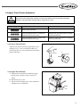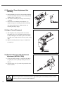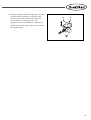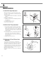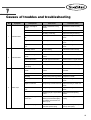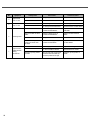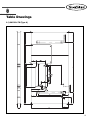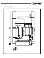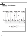
1
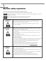
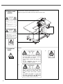
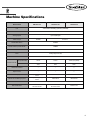
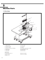
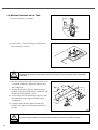
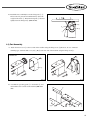
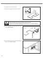
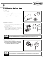
R
USER S MANUAL
KM-360J SERIES
High Speed 1-Needle,
Needle Feed Bottom
Hemming Sewing
Machine
(Mechanical Part)
lity
a
u
tQ
Besst Pricevice
Be st Ser
Be
1. Thank you for purchasing our product. Based on the rich expertise and
experience accumulated in industrial sewing machine production, SUNSTAR
will manufacture industrial sewing machines, which deliver more diverse
functions, high performance, powerful operation, enhanced durability, and
more sophisticated design to meet a number of user’s needs.
2. Please read this user’s manual thoroughly before using the machine. Make
sure to properly use the machine to enjoy its full performance.
3. The specifications of the machine are subject to change, aimed to enhance
product performance, without prior notice.
4. This product is designed, manufactured, and sold as an industrial sewing
machine. It should not be used for other than industrial purpose.
R
SunStar CO., LTD.
Machine Type
MODEL KM ‐ 360 J ‐
J
Attached with near
jean accessories
7
Automatic trimming
E
Electronic puller &
needle bar oscillating
system
M
Mechanical puller &
needle bar oscillating
system
Manual trimming
General
Contents
1. Machine safety regulations --------------------------------------------------------------------- 6
1.1) Transporting machine ---------------------------------------------------------------------------- 6
1.2) Installing machine --------------------------------------------------------------------------------- 6
1.3) Repairing machine -------------------------------------------------------------------------------- 6
1.4) Operating machine ------------------------------------------------------------------------------- 7
1.5) Safety devices ------------------------------------------------------------------------------------- 7
1.6) Caution mark position ---------------------------------------------------------------------------- 8
1-7) Contents of marks -------------------------------------------------------------------------------- 8
2. Machine Specifications --------------------------------------------------------------------------- 9
3. Machine Parts --------------------------------------------------------------------------------------- 10
3.1) Parts Name --------------------------------------------------------------------------------------- 10
4. Machine Installation ------------------------------------------------------------------------------ 11
4.1) Installation Environment ---------------------------------------------------------------------- 11
4.2) Electricity Environment ------------------------------------------------------------------------- 11
4.3) Machine Placement on the Table ----------------------------------------------------------- 12
4.4) Part Assembly ------------------------------------------------------------------------------------ 13
5. Preparation Before Use ------------------------------------------------------------------------- 15
5.1) Oil Supply ------------------------------------------------------------------------------------------ 15
5.2) Needle Installation ------------------------------------------------------------------------------ 15
5.3) Lower Thread Placement --------------------------------------------------------------------- 15
5.4) Bobbin Case Insertion and Disposal ------------------------------------------------------- 16
5.5) Lower Thread Winding ------------------------------------------------------------------------- 16
5.6) Upper Thread Tension Adjustment --------------------------------------------------------- 17
5.7) Remaining Thread Adjustment After Trimming ------------------------------------------ 18
5.8) Upper Thread Placement --------------------------------------------------------------------- 18
5.9) Pressured Air Input and Air Pressure Adjustment (KM-360J-7E(M)) -------------- 18
6. Maintenance ------------------------------------------------------------------------------------------ 20
6.1) Needle Bar Height Adjustment -------------------------------------------------------------- 20
6.2) Needle, Hook Timing Adjustment ----------------------------------------------------------- 20
6.3) Adjustment of Thread Take-up Lever Lubrication -------------------------------------- 20
6.4) Hook Lubrication Adjustment ----------------------------------------------------------------- 21
6.5) Puller (upper) Pressure Adjustment -------------------------------------------------------- 21
6.6) Presser Foot Pressure Adjustment --------------------------------------------------------- 21
6.7) Presser Foot Height Adjustment ------------------------------------------------------------ 22
6.8) Stitch Length Adjustment ---------------------------------------------------------------------- 22
6.9) Pneumatic Wiper Adjustment ---------------------------------------------------------------- 23
6.10) Trimmer Cam Adjustment ------------------------------------------------------------------- 23
6.11) Blade Position Adjustment ------------------------------------------------------------------ 23
6.12) Thread Take-up Lever Adjustment -------------------------------------------------------- 24
7. Causes of troubles and troubleshooting ----------------------------------------------- 25
8. Table Drawings ------------------------------------------------------------------------------------- 27
8.1) KM-360J-7M (Type A) ------------------------------------------------------------------------- 27
8.2) KM-360J-7M (Type B) ------------------------------------------------------------------------- 28
8.3) KM-360J-7M (Type C) ------------------------------------------------------------------------- 29
9. Pneumatic Circuit Diagram ------------------------------------------------------------------- 30
9.1) KM-360J-7M(E) ---------------------------------------------------------------------------------- 30
1
Machine safety regulations
Safety instructions on this manual are defined as Danger, Warning and Caution.
If you do not follow the instructoins, physical injuries and machine damages might be occurred.
Danger
: This indication should be observed definitely. If not, there will be a danger during the installation, conveyance and
maintenance of the machine.
Warning : When you follow this indication, injuries from the machine can be prevented.
Caution : When you follow this indication, error on the machine can be prevented.
1.1) Transporting
machine
Those in charge of transporting the machine should have a full understanding of the machine.
The following indications should be followed when the machine is being transported.
ⓐ More than 2 people must transport the machine.
ⓑ To prevent accidents from occurring during transportation, wipe off the oil on the
machine compeletely.
Danger
1.2) Installing
machine
Warning
The machine may not work properly or breakdown, if installed in certain places, Install the
machine where the following qualifications agree.
ⓐ Remove the package and wrappings from the top. Take special notice on the nails on the
wooden boxes.
ⓑ Dust and moisture stains and rusts the machine. Install an airconditioner and clean the
machine regularly.
ⓒ Keep the machine out of the sun.
ⓓ Leave sufficient space of more than 50cm behind, and on the right and left side of the
machine for repairing.
ⓔ EXPLOSION HAZARDS
Do not operate in explosive atmospheres. To avoid explosion, do not operate this machine
in an explosive atomsphere including a place where large quantities of aerosol spray
product are being used or where oxygen is being administered unless it has been
specifically certified for such operation.
ⓕ The machine is not provided with a local lighting due to the feature of machine.
Therefore the illumination of the working area must be fulfilled by end user.
[Refer] Details for machine installation are described in 4. Machine Installation.
1.3) Repairing
machine
Caution
6
When the machine needs to be repaired, only the assigned troubleshooting engineer educated
at the company should take charge.
ⓐ Before cleaning or repairing the machine, turn off the main power and wait 4 minutes till
the machine is completely out of power.
ⓑ Not any of the machine specifications or parts should be changed without consulting the
company. Such changes may make the operation dangerous.
ⓒ Spare parts produced by the company should only be used for replacements.
ⓓ Put all the safety covers back on the machine after the machine has been repaired.
1.4) Operating
machine
Warning
KM-360J series were designed as industrial sewing machines to conduct bottom hemming on
fabric and similar materials. Observe the following instructions during machine operation.
ⓐ Read through this manual carefully and completely before operating the machine.
ⓑ Wear proper clothes for work.
ⓒ Keep hands or other parts of the body away from the machine’s operation parts(needle,
shuttle, thread take-up lever, pulley, etc.) when the machine is operating.
ⓓ Keep the covers and finger guard on the machine during operation.
ⓔ Be sure to connect the earthing conductor.
ⓕ Turn off the main power and check if the switch is turned“off”before opening electric
boxes such as the control box.
ⓖ Stop the machine before threading the needle or checking after work.
ⓗ Do not step on the pedal when turning the power on.
ⓘ If possible, install the machine away from source of strong electrical noise such as high
frequency welding machines
[ Warning ]
Keep motor cover in place before operating, turn off power before inspecting or
adjusting.
1.5) Safety devices
Caution
ⓐ Safety label : It describes cautions during the machine operation.
ⓑ Thread take-up cover : It prevents any contact between body and take-up lever.
ⓒ Motor cover : A device to prevent hands, feet and clothing from getting jammed by the
motor.
ⓓ Label for specification of power : It describes cautions for safety to protect electric shock
during the motors’ rotation. (Voltage input / use Hz)
ⓔ Finger guard : It prevent contacts between finger and needle.
ⓕ, ⓖ Gear covers (left), (right) : They prevent fingers from contacting the conversion gear.
ⓐ
ⓕ
ⓒ
ⓑ
ⓖ
ⓔ
ⓓ
7
1.6) Caution mark
position
Caution mark is attached on the machine for safety.
When you operate the machine, follow the directions on the mark.
CAUTION
주 의
Do not operate without finger guard and
safety devices. Before threading, changing
bobbin and needle, cleaning etc. switch off
main switch.
손가락 보호대와 안전장치 없이 작동하지
마십시오.
실, 보빈, 바늘교환시나 청소전에는 반드시 주
전원의 스위치를 꺼 주십시오.
WARNING
경 고
Hazardous voltage will cause injury.
Be sure to wait at least 360 seconds before
opening this cover after turn off main switch
and unplug a power cord.
고압 전류에 의해 감전될 수 있으므로 커버를
열 때는 전원을 내리고 전원 플러그를 뽑고 나
서 360초간 기다린 후 여십시오.
1-7) Contents of
marks
Caution
1)
CAUTION
주 의
Do not operate without finger guard
and safety devices. Before threading,
changing bobbin and needle, cleaning
etc. switch off main switch.
Warning
손가락 보호대와 안전장치 없이 작동하지 마
십시오.
실, 보빈, 바늘교환시나 청소전에는 반드시
주전원의 스위치를 꺼 주십시오.
2)
WARNING
경 고
Hazardous voltage will cause injury.
Be sure to wait at least 360 seconds
before opening this cover after turn
off main switch and unplug a power
cord.
고압 전류에 의해 감전될 수 있으므로 커버
를 열 때는 전원을 내리고 전원 플러그를 뽑
고 나서 360초간 기다린 후 여십시오.
8
3)
2
Machine Specifications
Model Name
KM-360J-7E
KM-360J-7M
KM-360J-M
Use
Jeans bottom hemming (for heavy materials)
Lubrication
Automatic lubrication
Sewing Speed
Up to 4,000 spm
Stitch Length
2~4.2mm
2~5mm
Needle Bar Stroke
34.6mm
Thread Take-up Lever Stroke
70.8mm
Needle
DP×5 SERV 7 110
Hook
Rotary large hook (2x)
Pants Hem Size
8~35mm
Auto (Pneumatic)
14mm
14mm
14mm (foot pedal)
Manual
4mm
4mm
4mm
Automatic Trimmer
○
○
×
Wiper Device
○
○
×
Presser Foot Lift
Puller Driving System
Driven by the stepping pulse
motor
Mechanical
Mechanical
Needle Bar Oscillating System
Driven by the stepping pulse
motor
Mechanical
Mechanical
0.5MPa
Pneumatic Pressure
Main Shaft Motor
500W direct drive
AC servo motor
500W direct drive
AC servo motor
Clutch motor
9
3
Machine Parts
3.1) Parts Name
⑭
⑬
⑫
④
①
⒔
⒕
⑨
⑮
②
③
⑪
⑧
⒖
⑩
⑥
⒃
⑤
⑦
①
②
③
④
⑤
⑥
⑦
Thread winder
Pneumatic wiper
Presser bar lifter
Pneumatic auto presser bar lifter
Presser foot
Control box
Lap switch
Safety Gears
⑮ Thread Take-up Cover
⒃ Finger Guard
⒔ Motor Cover
10
⑧
⑨
⑩
⑪
⑫
⑬
⑭
Power switch
Oil window
Hammer
Pneumatic auto presser foot lifter
Sewing machine pulley
Program unit
Thread stand
⒕ Gear Cover (left)
⒖ Gear Cover (right)
4
Machine Installation
4.1) Installation Environment
A. Do not use the machine if the voltage is below or above 10% of the rated voltage to prevent error-driven accidents.
B. Check the required air pressure for the devices using air pressure such as air cylinder to prevent error-driven accidents.
C. Use the machine in the following environment to ensure safe operation.
→ Operating temperature : 5°~ 40°C
→ Storage temperature : - 10°~ 60°C
D. Humidity : 20~80% (relative humidity)
4.2) Electricity Environment
A. Power Voltage
The power voltage fluctuation should be maintained within 10% of the rated voltage.
The power frequency is recommended to remain within 1% of the rated frequency (50/60Hz).
B. Electromagnetic Wave Noise
Use a different power supply from a strong magnetic field and high-frequency product, and keep the sewing machine
away from them.
C. Use a safe low voltage when auxiliary devices and accessories are attached to the control box.
D. Take caution not to spill water or coffee into the control box or the motor.
E. Do not drop the control box and the motor.
Caution
Caution
Sewing machine must be installed by properly trained engineers.
Contact the sales agency or electricity engineer for wiring-related inquiry.
Considering that machine weighs 40Kg or above, two people are needed for machine installation.
Until the installation is complete, do not connect the power plug. If the foot step is mistakenly
stepped, it may operate the machine, causing injury to user.
Connect the earth wire. If the earth wire connection is incomplete, it may cause electric shock or
wrong operation.
Place motor covers on the head of the sewing machine and the motor.
11
4.3) Machine Placement on the Table
A. Fix the control box ① to the table.
②
①
[Fig. 1]
B. Put the oil fan ① on the marked place and fix the bed
hinge bracket② to the holes.
②
①
[Fig. 2]
Loosely fasten the bed hinge bracket fixing bolts and tightly fasten them after the bed hinge shaft is
assembled.
Caution
C. Place the sewing machine bed① on the top of the oil fan
② and make adjustment to align them. Then fix them
with a fixing bolt.
D. Assemble the bed hinge support③ and the bed hinge
bracket④ using the bed hinge shaft⑤, and fix them with
the bed hinge shaft tightening screw⑥.
E. Use the fixing bolt to fix the bed hinge support③ to the
bed. (Adjust the height using the bed hinge support
assembly part.)
F. Completely fasten the fixing bolt for the bed hinge
bracket⑦ and tightly fasten the bed hinge bracket④ to
the table.
①
②
⑥
③
⑤
⑦
④
[Fig. 3]
To prevent safety accidents, the sewing machine must be delivered by at least two people.
Danger
12
E. Install the motor and fully loosen the fixing nuts ①, ②.
Then, tension is generated around the belt ④ due to the
weight of the motor ③. Fasten the fixing nut ① first and
tightly fasten the fixing nut ② (KM-360-M).
④
②
③
①
[Fig. 4]
4.4) Part Assembly
A. Attach the motor cover ① to the rear side of the machine using the fixing screw ② (However, in case of manual
trimming type, attach the belt cover (A)①, (B)② to the rear side of the machine using the fixing screw③).
KM-360J-7E
KM-360J-7M
KM-360J-M
③
②
①
②
①
[Fig. 5]
[Fig. 6]
B. Assemble the operating panel ① to the bracket ②, and
attach them to the rear side of the machine (KM-360J7M).
①
②
[Fig. 7]
13
C. Install the thread stand ② on the table ①.
②
D. Hammer the head supporting stick ③ into the table.
③
①
[Fig. 8]
Caution
Make sure the head supporting stick completely inserted into the table.
Otherwise, when the sewing machine head is pushed backward, it is not stable and dangerous.
E. Install the lap switch ① beneath the table, and fix it with
a nail ② (KM-360J-7E(M)).
②
①
[Fig. 9]
F. Fix the manifolder bracket ① beneath the table and fix it
using a screw ② (KM-360J-7E(M)).
②
①
[Fig. 10]
14
5
Preparation Before Use
5.1) Oil Supply
①
A. Remove the rubber cap ① on the arm face and supply
oil through a funnel ②.
B. Oil should be supplied until the scale is located between
the upper and lower limit of the oil gauge ③.
②
③
[Fig. 11]
5.2) Needle Installation
A. Turn the sewing pulley and place the needle bar ① at the
highest position.
B. Loosen the fixing screw.
C. Make the long groove of the needle ② headed toward
the left, and fully insert the needle into the hole as in the
figure. And fix the needle with a fixing screw.
User’s
work
direction
Needle
direction
①
③
[Fig. 12]
The power switch must be turned off for needle installation.
If the pedal is accidentally pressed, it may operate the sewing machine, causing injury to user.
Caution
5.3) Lower Thread Placement
①
A. Insert the bobbin into the bobbin case as in the figure.
B. Pass the lower thread through the slot ① of the bobbin
case and the lower part of the tension spring ②.
②
[Fig. 13]
Looking from the back of the bobbin case, the bobbin inserted should be spun counter-clockwise.
Caution
15
5.4) Bobbin Case Insertion and Removal
Open the hook cover and push the bobbin into the hook with
the bobbin case handle held until the click sound is heard.
①
②
[Fig. 14]
If the bobbin case is not properly placed, thread entanglement or bobbin ejection might result during
machine operation.
Caution
5.5) Lower Thread Winding
A. Turn on the power switch.
B. Insert the bobbin ① into the thread winder shaft ②.
C. Wind the thread around the bobbin ① several times in
the arrow direction.
D. Push the thread winder lever ③ into the bobbin
direction.
E. Lift the presser bar with the presser bar lifter.
F. When the pedal is stepped, the sewing machine starts
operating, and the thread is wound around the bobbin.
G. When thread winding is complete, the thread winder
lever ③ is automatically returned.
H. Separate the bobbin and cut the thread with the thread
winder blade ④.
④
①
③
②
※ Loosen the adjusting screw ⑤ and adjust the thread
winder adjusting plate ⑥ to adjust the thread volume
on the bobbin.
Bobbin thread volume should be up to 80% of the maximum volume.
Caution
16
⑤
⑥
[Fig. 15]
5.6) Upper Thread Tension Adjustment
Turn off the power switch when inserting or removing the bobbin case. If the pedal is mistakenly
stepped, it may operate the sewing machine, causing injury to user.
Caution
Sewing Type
Cause
Corrective Action
Evenly created good stitch
If the upper thread tension is too weak or the
lower thread tension is too strong
Strengthen the upper thread tension or weaken
the lower thread tension.
If the upper thread tension is too strong or the
lower thread tension is too weak
Weaken the upper thread tension or strengthen
the lower thread tension.
5.6.1) Lower Thread Tension
Adjust the lower thread tension by adjusting the tension
adjusting screw ① to the extent that the bobbin case
slowly drops due to its own weight when the thread tip is
held as in the figure.
①
Stronger
Weaker
[Fig. 16]
5.6.2) Upper Thread Tension
A. Adjust the lower thread tension and then the upper
thread tension to produce evenly created good
stitches.
B. Pull down the presser bar.
C. Turn the tension adjusting nut ② of the main thread
adjusting device for adjustment.
Weaker
②
Stronger
[Fig. 17]
17
5.7) Remaining Thread Adjustment After
Trimming
A. During trimming, the tension of the main thread adjuster
is not involved, while the tension of the auxiliary thread
adjusting device ① plays a role.
B. The standard remaining thread length after trimming is
35~40mm.
C. If the tension of the auxiliary thread adjuster ① is
adjusted stronger, the remaining thread after trimming
gets shorter. If the tension is adjusted weaker, the
remaining thread gets longer.
Stronger
Weaker
①
[Fig. 18]
5.8) Upper Thread Placement
A. Turn the pulley of the sewing machine to locate the
thread take-up lever ① at the highest position and pass
the thread through the thread take-up lever. This makes
threading easier and prevents thread escape when sewing
starts.
B. Make the remaining thread as long as 35~40mm from
the needle eye.
[Fig. 19]
5.9) Pressured Air Input and Air Pressure
Adjustment (KM-360J-7E(M))
A. Connect the quick joint plug ② attached to the table to
the quick joint socket ① through which pressured air
flows in.
B. Open the finger valve ③ to make the pressured air flow
into the machine.
③
②
①
[Fig. 20]
When the finger valve is closed after operation, the remaining air is automatically released, and the
remaining pressure is marked at 0MPa (0Kgf/cm2).
Caution
18
C. Pull up the adjusting handle at the upper part of the filter
regulator and turn it clockwise as in the figure. This
increases pressure. If it is turned counter-clockwise,
pressure decreases. Adjust the pressure to the
appropriate level of 0.49~0.54MPa (5~5.5Kgf/cm2) as
marked on the pressure gauge and then return and settle
the adjusting handle.
[Fig. 21]
19
6
Maintenance
6.1) Needle Bar Height Adjustment
When the needle bar ① is at the lowest position, set the
carved line ⓐ of the needle bar ① to meet the bottom of the
oil rejecter cover ②.
A. Turn the pulley and place the needle bar ① at the lowest
position.
B. Remove the rubber cap ③.
C. Slightly loosen the screw ④ and adjust the position of
the needle bar ①.
D. Completely fasten the screw ④.
E. Place back the rubber cap ③.
②
ⓐ
④
①
③
①
[Fig. 22]
6.2) Needle, Hook Timing Adjustment
A. Turn the pulley and lift the needle bar from the lowest
position. As in the figure, set the carved line ⓐ in line
with the bottom of the oil rejecter cover ②. Make sure to
set the distance between the needle eye and the tip of the
hook at 0~0.5mm.
B. Loosen the three screws ⑤ and set the tip of the hook ③
in line with the center of the needle ④. Adjust the
distance between the tip of the hook ③ and the needle
④ at 0.05~0.1mm.
C. Tightly fasten the three screws ⑤.
②
ⓐ
①
⑤
④
③
[Fig. 23]
6.3) Adjustment of Thread Take-up Lever
Lubrication
As in the figure, when the mark ② on the lubrication
adjusting pin ① head is in line with the center of the thread
take-up lever crank shaft hole ③, lubrication volume is
maximum. When the pin is turned left or right and the mark
is adjusted toward the edge ⑤ of the link cam washer ④,
lubrication volume gets smaller.
If the edge of the link cam washer is passed, no lubricant is
supplied.
③
②
①
④
⑤
[Fig. 24]
20
6.4) Hook Lubrication Adjustment
Hook
A. Lubrication Volume Check
a. Conduct idle operation for some 3 minutes (at an
appropriate speed). Place the lubrication test sheet as
in the figure and operate the machine for 5 seconds
to check lubrication. Check oil volume sprayed to the
sheet.
b. Conduct the lubrication testing three times. If the oil
strip remains within the maximum and minimum
range, the lubrication is deemed proper (If
lubrication is too small, hook operation might not be
smooth, If lubrication is too much, the oil may stain
the fabric.)
B. Lubrication Volume Adjustment
Turn the lubrication volume adjusting screw ① on the
lower shaft front bushing clockwise (+ direction), and
then lubrication volume increases. If it is turned counterclockwise (- direction), lubrication volume decreases.
Lubrication test sheet
Oil strip
Oil strip
Min. limit
Max. limit
①
Decrease
Increase
[Fig. 25]
6.5) Puller (upper) Pressure Adjustment
If the pressure adjusting screw ① is turned clockwise,
pressure gets stronger, and vice versa.
After adjustment is complete, the fixing nut ② must be
fastened.
①
Stronger
Weaker
①
[Fig. 26]
6.6) Presser Foot Pressure Adjustment
Turn the pressure adjusting nut ① clockwise to increase the
pressure, and turn it counter-clockwise to decrease the
pressure.
①
Stronger
Weaker
[Fig. 27]
21
6.7) Presser Foot Height Adjustment
When the presser bar lifter ② is lifted, the presser foot ① is
normally lifted 4mm. At this time, the distance between the
rollers (up) ⑥ and (down) ⑦ is 5mm.
A. Loosen the nut ③ and unfasten the pressure adjusting
screw ④.
B. Lift the roller (up) ⑥ with the presser bar lifter ②.
C. Remove the rubber cap ⑤ from the face plate.
D. Slightly loosen the tightening screw ⑧ and adjust the
position of the presser bar ⑨ to set the distance between
the roller (up) ⑥ and the roller (down) ⑦ at 5mm.
E. Fasten the tightening screw ⑧.
F. Put back the rubber cap ⑤.
G. Adjust the puller (up) pressure with the pressure
adjusting screw ④ and fasten the nut ③.
H. Loosen the tightening screw and move the presser bar
lifter arm to adjust the presser bar height at 4mm.
④
③
⑧
②
⑤
①
⑥
⑦
⑪
⑩
①
5mm
4mm
6.8) Stitch Length Adjustment
The default stitch length is 2.9mm.
A. Loosen the tightening screw ① and remove the puller
gear cover (right) ②.
B. Set the desired stitch length using the stitch length table
and make a new conversion gear ready.
C. Loosen the tightening screw ③ and remove the present
conversion gear ④.
D. Replace it with a new conversion gear and fasten the
tightening screw ③.
E. After the conversion gear replacement, adjust the needle
feed volume.
F. Press the feed adjustment button ⑤ on the arm face.
G. Turn the pulley ⑥ until the feed adjusting button ⑤ is
inserted into the groove of the stitch length conversion
cam and a click sound is heard.
H. Turn the pulley to make the stitch length marked on the
pulley in line with the punched mark.
I. Release the feed adjusting button ⑤ and check if the
pulley ⑥ is smoothly operating.
[Fig. 28]
U
26
28
30
32
34
36
38
③
④
STITCH LENGTH
2.0
2.3
2.6
2.9
3.3
3.7
4.2
②
①
⑤
D
38
36
34
32
30
28
26
⑥
③
[Fig. 29]
The stitch length may change depending on fabric type and thickness. Readjust the stitch length after
checking the sewing condition.
Caution
※ See the program unit operating method for step motor's stitch length adjustment (KM-360J-7E).
22
6.9) Pneumatic Wiper Adjustment
A. Release air pressure.
B. Turn the pulley to place the thread take-up lever at the
highest position.
C. Pull the wiper ① and loosen the nut ②. Adjust the wiper
position as in the figure and fasten the nut ②.
D. Loosen the nut ③ and set the distance between the
needle tip and the wiper at some 1~2mm.
E. Return the wiper ① back to the original place.
③
②
①
[Fig. 30]
6.10) Trimmer Cam Adjustment
A. Turn the pulley and set the thread take-up lever at the
highest position.
B. Press the solenoid lever ③ to make the trimmer cam
roller ① inserted into the trimmer cam ②.
C. Turn the pulley to make the needle bar's carved line meet
the bottom of the oil reject cover ④. Then adjust the
trimmer cam to make the trimmer main lever ⑤ move to
the left.
D. Loose the trimmer cam tightening screw ⑥ for
adjustment. When adjustment is complete, tightly fasten
the screw.
⑤
①
⑥
④
②
③
[Fig. 31]
6.11) Blade Position Adjustment
A. Remove the rubber cap ①.
B. Turn the pulley to place the thread take-up lever at the
highest position.
C. Push the trimmer cam roller ② into the trimmer cam ③
and turn the pulley until the moving blade ④ can move
in full.
D. Loosen the trimmer lever screw ⑥ to set the distance
between the moving blade ④ and the roller (down) ⑤ at
0.5mm. When adjustment is complete, fasten the screw.
E. Reassemble the rubber cap ①.
⑥
⑤
①
②
③
④
[Fig. 32]
23
6.12) Thread Take-up Lever Adjustment
A. Loosen the nut ①.
B. Turn the adjusting screw ② to set the distance between
the thread release lever roller ③ and the trimmer cam at
0.5mm.
C. Fasten the nut ①.
③
①
②
[Fig. 33]
24
7
Causes of troubles and troubleshooting
No
1
2
3
Symptom
Needle breaks
Checkpoints
Root cause
Corrective action
Direction and height of
needle
Needle is inserted into wrong
direction.
Reinsert the needle correctly.
Needle
Needle is bent.
Replace the needle.
Bad timing of feed dog.
Adjust the timing of feed dog.
Ascending level of needle
bar
Bad timing of needle and hook.
Adjust the timing of needle and
hook.
Height of needle
Bad timing of needle and hook.
Adjust the timing of needle and
hook.
Gap between needle and
hook
Bad timing of needle and hook.
Adjust the timing of needle and
hook.
Threading method
Wrong threading.
Thread the needle correctly.
Needle
Bent needle or broken needle tip.
Replace the needle.
Direction and height of
needle
Needle inserted in the wrong
position.
Insert the needle correctly.
Upper thread tension
Too tight upper thread tension.
Reduce tension of upper thread.
Lower thread tension
Too tight lower thread tension.
Reduce tension of lower thread.
Working capacity of take-up
lever spring
Loose upper thread.
Adjust take-up lever spring.
Direction and height of
needle
Needle inserted in the wrong
position.
Reinsert the needle in the right
direction.
Needle
Bent needle or broken needle tip.
Replace the needle.
Threading
Thread passing at wrong position.
Replace the needle.
Ascending level of needle
bar
Wrong timing of needle and hook.
Adjust the timing of needle and
hook.
Height of needle bar
Wrong timing of needle and hook.
Adjust the timing of needle and
hook.
Gap between needle and
hook
Wrong timing of needle and hook.
Adjust the timing of needle and
hook.
Remaining length of upper thread
is short .
Adjust the thread adjusting
device.
Racing-proof spring of
bobbin case
Due to bobbin racing during
trimming, lower thread dropping
from bobbin case becomes too
short to go up.
Replace the racing protection
spring.
Take-up lever spring
Unable to lift lower thread due to
weak take-up lever spring.
Adjust the working capacity of
take-up lever spring.
Thread breaks
Stitch skips
25
No
4
5
6
7
26
Symptom
Checkpoints
Root cause
Corrective action
Upper thread
does not sink.
Too tight upper thread tension.
Reduce tension of upper thread.
Too loose lower thread tension.
Increase tension of lower thread.
Lower thread
does not sink.
Too weak upper thread tension.
Increase upper thread tension.
Too strong lower thread tension.
Decrease tension of lower thread.
Tension of fixed blade
Tension not aligned between
movable and fixed blades.
Adjust tension of movable and
fixed blade.
Edge of movable and fixed
blades
Abrasion in blade groove of
movable and fixed blades.
Replace movable and fixed
blades.
Direction of needle
Wrong needle insertion.
Reinsert the needle correctly.
Check the crossing of
trimmer cam notch mark
and blade
Insufficient crossing quantity of
movable and fixed blade.
Adjust the strokes of movable
and fixed blades.
Too strong upper thread tension.
Adjust tension of upper thread.
Too thick a needle for thread.
Check thickness of needle.
Take-up lever pulls out the upper
thread because the needle up
and down position is too high.
Adjust the up-stop position of
needle.
Trimming errors
Upper thread is
pulled out when
sewing
commences.
Check the Up-stop position
of needle
8
Table Drawings
8.1) KM-360J-7M (Type A)
27
8.2) KM-360J-7M (Type B)
28
8.3) KM-360J-7M (Type C)
29
9
Pneumatic Circuit Diagram
9.1) KM-360J-7M(E)
30