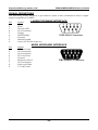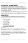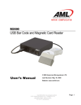
1
Model 6000 Wireless Bar Code Decoder
Model 6200 Wireless Host
Model 6300 USB Wireless Host
USER’S MANUAL
2190 Regal Parkway • Euless, TX 76040
(817)571-9015 • (800)648-4452 • Fax: (817)685-6232
www.barcodepower.com
FCC NOTICE
NOTE: This equipment has been tested and found to comply with the limits for a Class B
digital device, pursuant to Part 15 of the FCC Rules. These limits are designed to provide
reasonable protection against interference in a residential installation. This equipment
generates, uses, and can radiate radio frequency energy and, if not installed and used in
accordance with the instruction manual, may cause interference to radio communications.
However, there is no guarantee that interference will not occur in a particular installation.
If this equipment does cause interference to radio or television reception, which can be
determined by turning the equipment off and on, the user is encouraged to try to correct
the interference by one or more of the following measures:
-- Reorient or relocate the receiving antenna.
-- Increase the separation between the equipment and the receiver.
-- Connect the equipment into an outlet on a circuit different from that to which the
receiver is connected.
-- Consult the dealer or an experienced radio/TV technician for help.
There are no user-serviceable internal parts. Changes or modifications not expressly
performed by the manufacturer will void the manufacturer’s warranty and may void the
user’s legal authority to operate the equipment.
FCC PRODUCT LABEL INFORMATION
This device complies with FCC Part 15. Operation is subject to the following two
conditions: (1) this device may not cause harmful interference and (2) this device must
accept any interference received, including interference that may cause undesired
operation.
TRADEMARK ACKNOWLEDGEMENTS
IBM, AT/XT, and PS/2 are registered trademarks of International Business Machines
Corporation.
MS-DOS, Windows, and Notepad are trademarks of Microsoft Corporation.
PSC and Quickscan 6000 (QS6000) are trademarks of PSC Corporation.
Metrologic MS-941 Laser is a trademark of Metrologic Instruments, Inc.
All other trademarks or registered trademarks of other companies are used only for
explanation without intent to infringe.
© Copyright American Microsystems, Ltd. 2002. All rights reserved.
American Microsystems, Ltd.
M6000/M6200/M6300 User's Guide
TABLE OF CONTENTS
Introduction ....................................................................................................... 2
Features ............................................................................................................... 3
Setup Instructions
M6200 Wireless Host.................................................................................. 4
M6300 USB Wireless Host......................................................................... 4
M6000 Wireless Bar Code Decoder......................................................... 5
Usage Guidelines ............................................................................................. 5
Setting the Host ID ........................................................................................... 6
Setting the Portable ID..................................................................................... 6
Default Settings ................................................................................................. 7
Changing the Default Settings...................................................................... 9
Programming Guide........................................................................................10
Code 39................................................................................................................11
UPC.......................................................................................................................11
EAN......................................................................................................................12
UPC/EAN Supplements ................................................................................13
Interleaved 2 of 5...............................................................................................13
Codabar...............................................................................................................14
Code 128..............................................................................................................14
Code 93................................................................................................................15
MSI/Plessey.......................................................................................................15
Code 11................................................................................................................16
Preamble..............................................................................................................16
Postamble............................................................................................................16
Bar Code Options .............................................................................................17
Bar Code Edit.....................................................................................................18
Laser/CCD Options ........................................................................................19
Termination Character....................................................................................19
Host Keyboard Type........................................................................................20
Host Transmit Speed.......................................................................................20
Scan Beep............................................................................................................20
Portable Acknowledge Beep..........................................................................20
Diagnostics.........................................................................................................21
Portable Shutdown Time................................................................................21
Signal Definitions.............................................................................................22
1
American Microsystems, Ltd.
M6000/M6200/M6300 User's Guide
INTRODUCTION
Together with the Model 6000 Wireless Bar Code Decoder (M6000), the Model 6200
Wireless Host (M6200) and the Model 6300 USB Wireless Host (M6300) provide the user
with the means of converting an undecoded laser, CCD, or wand into a wireless device. By
allowing many types of input devices, this system provides users the ability to customize
according to their needs and is an affordable alternative to purchasing an integrated
wireless system.
The M6200/M6300 Wireless Host is used as a companion to the M6000, receiving the
wireless data and converting it into useable IBM compatible PC keyboard data. For the AT
or PS/2 PC keyboard interface, the Model 6200 Wireless Host (M6200) is used. For the USB
keyboard interface, the Model 6300 USB Wireless Host (M6300) is used.
The M6200/M6300 Wireless Host also features a bar code scanner interface, allowing it to
function locally as a decoder for laser, CCD, and wand devices, in addition to its normal
function of receiving and converting wireless data. The M6000 Wireless Bar Code Decoder
and the M6200/M6300 Wireless Host can be custom configured using the
M6000/M6200/M6300 Setup Menu to allow multiple wireless hosts, as well as, other
standard options that allow the equipment to be tailored for your individual data collection
application.
The M6000's simple but rugged construction allows for extended reliable operation. Once
configured, simply connect a scanning device, push the on button and you are ready to
scan. The M6000 has a superior range, up to 150 feet, providing users with a wireless link
to an IBM compatible PC. Every valid scan is confirmed with an audible beep. The M6000
automatically turns off power after a few minutes, so batteries are not wasted or
accidentally discharged.
Reliability, ease-of-use and affordability make American Microsystems’ M6000 Wireless
Bar Code Decoder and M6200/M6300 Wireless Host system an excellent choice for wireless
bar code data collection.
2
American Microsystems, Ltd.
M6000/M6200/M6300 User's Guide
FEATURES
• Expandable: allows ten (10) M6000 Wireless Portables per wireless host by setting the
Portable ID. The total system allows up to eight (8) wireless hosts to be used, by setting
the Host ID.
• Reader automatically recognizes and reads the following bar code types:
Code 39
Codabar
Extended Code 39 (full ASCII)
Code 128
Interleaved 2 of 5
Code 93
UPC-A, UPC-E
Code 11
EAN-8, EAN-13
MSI/Plessey
UPC & EAN supplements (2 and 5 character)
• Supports any low cost 5 volt undecoded laser, CCD, or wand devices.
• Convenient momentary on button turns on the M6000 power. After a user-settable idle
time (in minutes), the M6000 automatically turns off the power so there are no
accidentally discharged batteries.
3
American Microsystems, Ltd.
M6000/M6200/M6300 User's Guide
SETUP INSTRUCTIONS
M6200 Wireless Host: AT and PS/2 Keyboard Connection
Step 1:
Turn off power to the computer.
Step 2:
Unplug the keyboard connector from the back of the computer. Note the style
of the connector. If the connector is 1/2” in diameter and has five (5) pins in a
semicircle configuration, then the connector is AT style. If the connector is
3/8” in diameter, then it is the PS/2 style. The keyboard will be one of these
two styles. The two supplied AT to PS/2 converters can be used to match the
style of your keyboard.
Step 3:
Locate the supplied
wedge cable. This cable
is black, and has a male
DB9 connector at one end
and a double connection
at the other end that uses
a keyboard receptacle (to
plug in your keyboard)
and a keyboard plug (to
plug into your
computer).
Step 4:
Connect the wedge cable
to the M6200’s keyboard
interface, the female DB9
connector, and then secure it using the two finger screws.
Step 5:
Plug the keyboard into the keyboard receptacle of the wedge cable. Use the
supplied AT to PS/2 converter, if needed, to match your style of keyboard. A
keyboard must be used with the M6200 for the wedge interface to function.
Step 6:
Plug the keyboard plug of the wedge cable into the keyboard port of the
computer. Use the supplied AT to PS/2 converter, if needed, to match the
style of the computer’s keyboard port.
Step 7:
The M6200 has now been installed. Turn on power to the PC. Once power is
on, you will hear a beep and notice that the LED on the front if the M6200 is
green.
M6300 USB Wireless Host: Microsoft Windows 98/ME/2000/XP
The 6 ft. A-B standard type USB cable is supplied. Installation on a Windows PC will be
similar to that of a USB keyboard device. Windows 98 may ask you for the Windows 98
System CD. On Windows 2000 systems and above, ignore the “Missing Authentication
Key” message, select “YES”, and allow Windows proceed with installation.
Step 1:
Before plugging in the M6300 to your PC’s USB port, make sure you have
available the licensed Microsoft Windows CD used for your installation. This
is important to make sure that the required drivers are compatible with your
particular installation.
Step 2:
With Windows running, connect the USB cable to the PC and to M6300 USB
interface. Follow any instructions Windows asks you to, if any.
4
American Microsystems, Ltd.
M6000/M6200/M6300 User's Guide
Step 3:
If the M6300 has been “enumerated” you will hear a series of beeps and the
LED will be GREEN. Repeat Step 2 for every USB port on your computer, as
Windows treats every USB port in the system individually. This also applies if
using a USB hub device. A self-powered USB hub is recommended.
NOTE: DO NOT USE USB EXTENSION CABLES with the M6300. The USB standard was
designed for keyboard cables with a length of 3 meters maximum. Use of a long
USB extension cable may cause improper operation. If extra cable length is needed,
the use of a USB hub device is required.
M6000 Wireless Bar Code Decoder
Step 1:
Insert the 9V battery into the M6000 battery compartment. Make note of the
battery polarity markings in the compartment. If the battery is inserted
backwards, the M6000 will not turn on.
Step 2:
Replace the battery compartment door. Now press the POWER button to
verify that the M6000 is working. When the POWER button is pressed and
released you will hear an audible beep.
Step 3:
Plug the bar code scanning device of your choice (laser, CCD, or wand) into
the 9-pin D-shell connector interface. Note that the bar code interface
connector has built-in cable locking tabs.
USAGE GUIDELINES
The Model 6200/6300 Wireless Host communicates to the M6000 Wireless Bar Code
Decoder using a radio frequency (RF) data link. The radio’s typical range is about 150 feet
in an unobstructed line-of-sight environment. Factors that affect the M6000 and the
M6200/M6300 Wireless Host’s performance in any given environment are related to the
physics of radio wave (electromagnetic wave) transmission, and include: distance,
reflection, cancellation, interference, and energy absorption.
Distance affects signal strength in that signal power diminishes rapidly with the “inverse
square rule”, which means as you go twice as far away there is only one-fourth of the total
signal strength present, and so on. The M6000 provides long battery life, but if there seems
to be a notable decrease in range, try replacing the battery with a new, fresh one.
Reflection from metal objects affect radio waves in the same way that a mirror reflects light;
radio waves typically do not pass well through metal objects. When using the M6000 and
the M6200/M6300 Wireless Host near metal objects, allow a sufficient distance of two feet
or so to allow radio waves to propagate. Using the Wireless Host directly on a metal work
surface is not preferred, but will not prevent the Wireless Host from working. Using a
M6000 radio when directly separated from the Wireless Host by a metal wall would reduce
transmission range or perhaps block the signal.
A side effect of reflection is wave cancellation, in which the signal strength coverage is
dependent on the exact position in a room; this effect is associated with “peaks” of strong
signal and “nulls” of weak signal. In addition, if possible, locate the Wireless Host in an
open area at least three feet from the ground to provide the best chance for uniform
coverage in a room. Nearby metal objects may tend to distort a uniform radio field pattern
because of this effect. You may have heard the effect of static "nulls" on your car's stereo
when stopped at a traffic signal, but when moving again the sound quality improves
because both "peaks" and "nulls" are being received. Moving the M6000 by an inch or two
to find a stronger wave "peak" can compensate for the occasional "nulls" when scanning.
Interference from other equipment may also be present in an environment. The M6000
radio’s 916.5 MHz frequency is located near the center of the FCC allocated Industrial,
5
American Microsystems, Ltd.
M6000/M6200/M6300 User's Guide
Scientific, and Medical (ISM) 902-928 MHz frequency band. Interference in this frequency
band is not common and not affected by cellular telephones or pagers. The 900 MHz
cordless telephones typically operate at each end of this ISM frequency band, and so would
not likely cause interference.
Absorption is the final factor affecting the performance of the M6000 and the
M6200/M6300 Wireless Host. Both the M6000 and the M6200/M6300 units transmit a safe
level of radio frequency energy; however, any radio signal is to some degree absorbed by
human body mass or other objects in close proximity. For example, the user’s body may
disrupt the line-of-sight path between the M6000 and the Wireless Host. The user will
likely find satisfactory use from wearing the M6000 at one’s waist, but to minimize the
affect of body mass, for better reception, wear the M6000 higher up on the body, such as in
a chest pocket or on the arm using an armband. For best reception, the M6000 can be
affixed to the top of some lasers or CCDs using Velcro strips, thereby keeping the radio at
arm’s length.
A factor affecting use on a Windows PC is the screen saver. Use of the screen saver is not
recommended, as it changes the focus of keyboard keystrokes away from your data
collection program. In so doing, the data can be lost. Make sure your data collection
program is active when scanning data and is always able to accept data from the keyboard.
SETTING THE HOST ID
In a multiple system, the Host ID is used to determine to which PC Host the M6000
communicates. The Portable ID is used to distinguish each M6000. Each M6200/M6300
Wireless Host (Host ID) supports up to ten (10) M6000’s (Portable ID’s). Each ID pair must
not be used more than once, or the data integrity will be compromised. The default setting
is Host ID=1 and must be changed if using more than one Wireless Host.
Step 1:
Make sure that a Wireless Host unit has been installed on the PC and
configured.
Step 2:
Locate the Model 6000/6200/6300 Setup Menu.
Step 3:
Scan the START bar code at the upper left corner of the menu.
Step 4:
Set the Host ID by scanning HOST ID ADDRESS and then scan the bar code (0
to 7), at the right side of the Setup Menu. This number should match that to be
used with the M6000 Wireless Bar Code Decoder.
Step 5:
If you wish to keep and store these changes, scan EXIT (SAVE CHANGES). If
you wish to discard these changes, and revert to your previous settings, select
EXIT (IGNORE CHANGES).
Step 6:
Open a text editor, such as Microsoft Notepad on your PC. Scan the START
bar code from the Setup Menu again. Then scan DIAGNOSTICS and the EXIT
(IGNORE CHANGES) bar code. Note that the current Host ID setting is
displayed along with other M6200/M6300 diagnostic information in the PC
window. If the Host ID setting is not correct, repeat the process starting at Step
3.
SETTING THE PORTABLE ID (M6000 only)
Step 1:
Make sure that an Wireless Host unit has been installed on the PC and
configured.
Step 2:
Locate the Model 6000/6200/6300 Setup Menu.
Step 3:
Scan the START bar code at the upper left corner of the menu.
6
American Microsystems, Ltd.
M6000/M6200/M6300 User's Guide
Step 4:
Set the Portable ID by scanning PORTABLE ID ADDRESS and then select the
number (0 to 9) to identify each M6000, at the right side of the Setup Menu.
Step 5:
Step 6:
Step 7:
If you wish to keep and store these changes, scan EXIT (SAVE CHANGES). If
you wish to discard these changes, and revert to your previous settings, select
EXIT (IGNORE CHANGES).
Open a text editor, such as Microsoft Notepad on your PC. Scan the START
bar code from the Setup Menu again. Then scan DIAGNOSTICS. Scan the
EXIT (IGNORE CHANGES) bar code. Note that the current Host ID and the
Portable ID settings are displayed along with other M6000 diagnostic
information in the PC window.
If the M6000 diagnostic data from Step 7 was displayed on the PC, the system
is configured correctly; however, if no data is displayed, make sure the
Wireless Host unit is connected and that the Host ID setting is correct and
unique. Verify the Host ID setting by connecting a scanning device to the
Wireless Host and scanning START, DIAGNOSTICS, and EXIT (IGNORE
CHANGES).
DEFAULT SETTINGS
The M6000 and the M6200/M6300 default settings can be restored, aborting all user
changes, using the Model 6000/6200/6300 Setup Menu by scanning START, RESET ALL
DEFAULTS, and EXIT (SAVE CHANGES). Using the Setup Menu, the individual settings
of the M6000 and the M6200/M6300 can be changed by the user, see Changing the Default
Settings. The M6000 and the M6200/M6300 are shipped from the factory with the
following default settings:
Code 39
Code 39 Decoder
Full ASCII
Mod 43 Check Digit
Send Check Digit
Concatenate Mode
ON
OFF
OFF
OFF
OFF
EAN
EAN Decoder
Zero Fill EAN-8 to EAN-13
Send EAN-13 Country Code
Send EAN-8 Country Code
Send EAN-13 Check Digit
Send EAN-8 Check Digit
ISBN Conversion
INTERLEAVED 2 of 5
I 2 of 5 Decoder
Check Digit
Send Check Digit
Fixed Length
Set Fixed Length #1
Set Fixed Length #2
ON
OFF
ON
ON
ON
ON
OFF
ON
None
OFF
OFF
02
06
UPC
UPC Decoder
Convert UPC-E to UPC-A
Convert UPC-A to EAN-13
Send UPC-A Number System
Send UPC-E Number System
Send UPC-A Check Digit
Send UPC-E Check Digit
UPC/EAN SUPPLEMENTS
Supplements Decoder
Allow 2 Digit Supplements
Allow 5 Digit Supplements
Require Supplements
Send Separator Space
CODABAR
Codabar Decoder
Send Start/Stop
CLSI Formatting
CLSI Check Digit
7
ON
OFF
OFF
ON
ON
ON
ON
OFF
ON
ON
OFF
OFF
ON
OFF
OFF
OFF
American Microsystems, Ltd.
CODE 128
Code 128 Decoder
UCC-128 Verification
Send Mod 10 Check Digit
MSI/PLESSEY
MSI/Plessey Decoder
Two Check Digits Required
First Check Digit Mod 11
Send 1st Check Digit
Send 2nd Check Digit
ISBN Plessey
PREAMBLE
Enter Preamble
Preamble Send Delay
Active Types
M6000/M6200/M6300 User's Guide
ON
OFF
ON
OFF
OFF
OFF
OFF
OFF
OFF
OFF
0.0 sec
ALL
BAR CODE OPTIONS
Send Bar Code Type ID
OFF
Duplicate Reads Allowed
ON
Bar Code Function Keys
OFF
Bar Code Special Keys
ON
Bar Code Term
Char Override
OFF
Keyboard Auto Caps/ Num Lock ON
Alternate Numeric Keys
OFF
LASER/CCD OPTIONS
Laser Trigger Mode
Laser/CCD Timeout
Read Delay
Read Verification
CODE 93
Code 93 Decoder
Concatenate Mode
ON
OFF
CODE 11
Code 11 Decoder
Two Check Digits Required
Send 1st Check Digit
Send 2nd Check Digit
OFF
OFF
OFF
OFF
POSTAMBLE
Enter Preamble
Postamble Send Delay
Active Types
OFF
0.0 sec
ALL
BAR CODE EDIT
Bar Code Editing
Enter # of Leading Chars to Strip
Enter # of Trailing Chars to Strip
Enter Bar Code Type to Edit
Strip Leading&Trailing Spaces
OFF
0
0
ALL
OFF
TERMINATION CHARACTER
0
2) Carriage Return (USB, Enter Key)
3 sec
0.0 sec HOST TRANSMIT SPEED
0
3) Fast
HOST KEYBOARD TYPE
PORTABLE ID ADDRESS
HOST ID ADDRESS
PORTABLE SHUTDOWN TIME
0) USA (English)
Host Unit ID
SCAN BEEP
Length: 1) Medium Short
Tone:
6) Medium High
Portable Unit
1
1
10 minutes
PORTABLE ACKNOWLEDGE BEEP
0) Short
5) High
6) Number of beeps: 2
8
American Microsystems, Ltd.
M6000/M6200/M6300 User's Guide
CHANGING THE DEFAULT SETTINGS
You can easily change the settings by simply scanning the bar code options located on the
M6000/M6200/M6300 Setup Menu. The Setup Menu is a sheet of bar codes supplied with
this manual and will be available for download from the American Microsystems’ website:
www.barcodepower.com.
The basic programming sequence is similar to the process used in Setting the Host ID and
follows the form:
START
..CATEGORY
…OPTION (0 to 9)
….ON/OFF or NUMBER DATA
…..EXIT (SAVE CHANGES) or EXIT (IGNORE CHANGES)
Follow these instructions to change any setting:
Step 1:
Scan the START bar code at the top left corner of the M6000/M6200/M6300
Setup Menu. This puts the M6000 and the M6200/M6300 into the program
mode.
Step 2:
Scan one of the Category labels (i.e. Code 39, UPC, and Beep)
Step 3:
Select the desired numbered option by scanning one of the numeric labels (0 –
9). If an invalid choice is made the M6000 and the M6200/M6300 will emit an
error beep. If there is only one option under the label, go to Step 4.
Step 4:
If there is a (ON/OFF) next to the description, scan ON to enable or OFF to
disable the option.
Example: To disable the UPC-A Check Digit perform the following:
1) Scan the UPC category label.
2) Scan the option 5) label to select the Send UPC-A Check Digit option.
3) Scan the OFF label to disable the option.
If there is a range of numbers next to the option, scan numeric labels located
on the right side of the Setup Menu Sheet. Some options require only one (1)
digit, these appear as (0-9). Others require two digits, for example (0.0-9.9),
and both digits must be entered.
Example: To set the Preamble Send Delay to one (1.0) second, perform the
following:
1) Scan the PREAMBLE category label.
2) Scan the (1) digit for Preamble Send Delay.
3) Scan 1 for the one digit and scan 0 for the tenths digit. This selects the
time 1.0, or 1 second.
NOTE: The default setting is 0.0 seconds.
Step 5:
If you want to make another change within the same Category, you can
scan another option number (i.e. return to Step 3 above). If you want to
change an option in a different Category, you must first scan the new
category (i.e. return to Step 2 above and repeat the steps).
Step 6:
When you have finished making all the changes, you can either:
9
American Microsystems, Ltd.
M6000/M6200/M6300 User's Guide
1)
Scan the EXIT (SAVE CHANGES) label on the Setup Menu to save all
the changes and then exit the menu to return to normal bar code
reader operation.
2)
Scan the EXIT (IGNORE CHANGES) label on the Setup Menu to
discard, without saving, all the changes and then exit the menu to
return to normal bar code reader operation.
PROGRAMMING GUIDE
START
The START bar code places the reader into the program mode. After scanning this
label, the reader will emit three short beeps to indicate that it is in the program
mode.
EXIT (SAVE CHANGES)
Scan this bar code to exit the program mode and save all of the changes. After
scanning this label, the reader will beep twice then delay approximately one second
and emit three short beeps to indicate that it accepted the changes.
EXIT (IGNORE CHANGES)
Scan this bar code to exit the program mode and discard all of the current changes.
The reader will use the settings that were in effect before entering the program
mode.
RESET ALL DEFAULTS
Scan this bar code to reset all options to their default settings.
NOTE: Defaults are marked with “*”.
0-9 BAR CODES
These bar codes are scanned to select various options and enter programmable data
into the reader.
ON
OFF
NOTE: Scan option 9) to reset all of the options within the current Category back
to default.
If the option has an (ON/OFF) beside the description, scan the ON bar code to turn
on the current option.
If the option has an (ON/OFF) beside the description, scan the OFF bar code to turn
off the current option.
FULL ASCII CHART
The Full ASCII Chart is located on the back of the Setup Menu. This chart contains
the entire ASCII character set (128 characters). Use this chart to enter Preamble and
Postamble character strings as well as the Termination Character and Bar Code
Type to Edit options.
ADDITIONAL NOTES:
If the description beside the option contains:
(ON/OFF)
Then scan either an ON or OFF label to set the option.
(CHART)
Then scan one or more characters from the Full ASCII Chart.
(0-9)
Scan the desired character from the 0-9 labels.
(00-99)
Scan two desired characters from the 0-9 labels.
(0.0-9.9)
Scan two characters from the 0-9 labels to set the time from
0.0 to 9.9 seconds.
10
American Microsystems, Ltd.
M6000/M6200/M6300 User's Guide
CODE 39
0) CODE 39 DECODER
ON*
1) FULL ASCII
Enable reading Code 39 bar codes.
OFF
Disable reading Code 39 bar codes.
ON
Enable the Full ASCII Extension to Code 39. Option 0) above
must be set on.
OFF*
Disable the Full ASCII Extension to Code 39. This sets the
reader to the standard Code 39 mode.
2) MOD 43 CHECK DIGIT
ON
Enable the Mod 43 Check Digit for Code 39. When this
option is enabled, only Code 39 labels that contain a valid
check digit will be read.
OFF*
3) SEND CHECK DIGIT
ON
OFF*
Disable the Mod 43 Check Digit. Check digit verification will
not be performed.
Transmit the Mod 43 Check Digit with the bar code data.
Requires option 2) above to be set on.
Do not transmit the Mod 43 Check Digit.
4) CONCATENATE MODE
ON
Enable Concatenate Mode. The concatenate mode allows the
reader to accumulate multiple bar codes in its buffer, then
sends them to the computer just like they were a single bar
code. When a Code 39 label containing a leading space is
read, the reader emits two short beeps and buffers the data
without transmission. This process continues until a Code
39 label without a leading space is read or 128 characters are
buffered. A Code 39 bar code label that only contains a
single or multiple dashes (minus sign) will clear the buffer.
OFF*
Disable Concatenate Mode.
UPC
0) UPC DECODER
ON*
OFF
Enable reading UPC-A and UPC-E bar codes.
Disable reading UPC-A and UPC-E bar codes.
1) CONVERT UPC-E TO UPC-A
ON
Convert all UPC-E labels to their UPC-A equivalents before
transmission. After conversion, the reader will follow the
UPC-A programming options.
OFF*
No conversions will be performed.
11
American Microsystems, Ltd.
M6000/M6200/M6300 User's Guide
2) CONVERT UPC-A TO EAN-13
ON
Convert all UPC-A labels to an equivalent EAN-13 format by
inserting a leading zero. After conversion, the reader will
follow the EAN-13 programming options.
OFF*
No conversions will be performed.
3) SEND UPC-A NUMBER SYSTEM
ON*
Transmit the UPC-A Number System character.
OFF
Do not transmit the UPC-A Number System character.
4) SEND UPC-E NUMBER SYSTEM
ON*
Transmit the UPC-E Number System character.
OFF
Do not transmit the UPC-E Number System character.
5) SEND UPC-A CHECK DIGIT
ON*
Transmit the UPC-A Check Digit character.
OFF
Do not transmit the UPC-A Check Digit character.
6) SEND UPC-E CHECK DIGIT
ON*
Transmit the UPC-E Check Digit character.
OFF
Do not transmit the UPC-E Check Digit character.
EAN
0) EAN DECODER
ON*
OFF
Enable reading EAN-8 and EAN-13 bar codes.
Disable reading EAN-8 and EAN-13 bar codes.
1) ZERO FILL EAN-8 TO EAN-13
ON*
Add five leading zeros to EAN-8 labels. After conversion,
the reader will follow the EAN-13 programming options.
OFF
No conversions will be performed.
2) SEND EAN-13 COUNTRY CODE
ON*
Transmit the EAN-13 Country Code.
OFF
Do not transmit the EAN-13 Country Code.
3) SEND EAN-8 COUNTRY CODE
ON*
Transmit the EAN-8 Country Code.
OFF
Do not transmit the EAN-8 Country Code.
4) SEND EAN-13 CHECK DIGIT
ON*
Transmit the EAN-13 Check Digit character.
OFF
Do not transmit the EAN-13 Check Digit character.
5) SEND EAN-8 CHECK DIGIT
ON*
Transmit the EAN-8 Check Digit character.
OFF
6) ISBN CONVERSION
ON
OFF*
Do not transmit the EAN-8 Check Digit character.
Convert 13 DIGIT BOOKLAND/EAN (978) prefix to its
corresponding 10-digit ISBN number.
Do not convert Bookland/EAN to an ISBN number.
12
American Microsystems, Ltd.
M6000/M6200/M6300 User's Guide
UPC/EAN SUPPLEMENTS
0) SUPPLEMENTS DECODER
ON
Enable reading UPC, EAN & Bookland supplements.
OFF*
Disable reading UPC, EAN & Bookland supplements.
1) ALLOW 2 DIGIT
ON*
OFF
2) ALLOW 5 DIGIT
ON*
OFF
3) REQUIRE UPC
SUPPLEMENTS
ON*
OFF
4) REQUIRE EAN
SUPPLEMENTS
ON*
OFF
5) REQUIRE BOOKLAND
SUPPLEMENTS
ON*
OFF
Enable reading 2 digit supplements. Option 0) above must
be set on.
Disable reading 2 digit supplements.
Enable reading 5 digit supplements. Option 0) above must
be set on.
Disable reading 5 digit supplements.
Enable reading UPC supplements. Option 0) above must be
set on.
Disable reading UPC supplements.
Enable reading EAN supplements. Option 0) above must be
set on.
Disable reading EAN supplements.
Enable reading Bookland supplements. Option 0) above
must be set on.
Disable reading Bookland supplements.
6) SEND SEPARATOR SPACE
ON
Inserts a space between the standard bar code data and the
supplemental data.
OFF*
No separator space is inserted.
INTERLEAVED 2 OF 5
0) I 2 OF 5 DECODER
ON*
OFF
Enable reading Interleaved 2 of 5 bar codes.
Disable reading Interleaved 2 of 5 bar codes.
1) CHECK DIGIT: 0=NONE, 1=USS, 2=OPCC
Specifies which check digit type will be used with Interleaved 2 of 5:
0* =
None (no check digit required)
1
=
Uniform Symbology Specification (3-1-3 mod 10)
2
=
Optical Product Code Council (2-1-2 mod 10)
2) SEND CHECK DIGIT
ON
OFF*
Transmit the Interleaved 2 of 5 check digit with the bar code
data.
The check digit is not transmitted.
13
American Microsystems, Ltd.
3) FIXED LENGTH
M6000/M6200/M6300 User's Guide
ON
Read only Fixed Length Interleaved 2 of 5 bar code labels
that match the lengths defined in options 4) & 5) below. The
check digit can be on or off.
OFF*
Disable Fixed Length mode. Read all Interleaved 2 of 5 labels
without regard to length.
4) SET FIXED LENGTH #1 (02-60)
Sets the first valid Fixed Length for Interleaved 2 of 5. Scan a two-digit
value to enter the length. Valid lengths are 02 to 60 characters. By
definition, the lengths of Interleaved 2 of 5 labels are an even number
of characters. The default Fixed Length is 2 characters.
5) SET FIXED LENGTH #2 (02-60)
Sets a second valid Fixed Length for Interleaved 2 of 5. Scan a twodigit value to enter the length. The default length is set to 6 characters.
CODABAR
0) CODABAR DECODER
ON *
OFF
1) SEND START/STOP
ON
OFF *
2) CLSI FORMATTING
ON
OFF *
3) CLSI CHECK DIGIT
ON
OFF*
Enable reading Codabar bar codes.
Disable reading Codabar bar codes.
Transmit the Codabar start/stop characters.
Do not transmit the Codabar start/stop characters.
The reader will insert a blank after the 1st, 5th, and 10th
characters of a 14-character Codabar label. The label length
does not include the start and stop characters.
Disable CLSI formatting.
Enable the CLSI check digit. When this option is enabled, all
fourteen digit numeric bar codes must contain a valid check
digit.
Disable the CLSI check digit. Check digit verification will
not be performed.
CODE 128
0) CODE 128 DECODER
ON *
OFF
Enable reading Code 128 bar codes.
Disable reading Code 128 bar codes.
1) UCC-128 VERIFICATION
ON
A valid Mod 10 Check Digit is required on UCC-MOD 10
bar codes. (Applies to 20-digit serial shipping container bar
codes.)
OFF *
UCC-MOD 10 bar codes are accepted without valid Mod 10
Check Digits.
14
American Microsystems, Ltd.
M6000/M6200/M6300 User's Guide
2) SEND MOD 10 CHECK DIGIT
ON *
Transmit the Mod 10 Check Digit with the bar code entry.
OFF
Do not transmit the Mod 10 Check Digit.
CODE 93
0) CODE 93 DECODER
ON*
OFF
Enable reading Code 93 bar codes.
Disable reading Code 93 bar codes.
1) CONCATENATE MODE
ON
Enable Concatenate Mode. The concatenate mode allows the
reader to concatenate multiple bar codes in its buffer, and
then sends them to the computer just like they were a single
bar code. When a Code 93 label with a leading space is read,
the reader emits two short beeps and buffers the data
without transmission. This process continues until a Code 93
label without a leading space is read or 128 characters are
buffered. A Code 93 bar code label that only contains a
single or multiple dashes (minus sign) will clear the buffer.
OFF*
Disable Concatenate Mode.
MSI/PLESSEY
0) MSI/PLESSEY DECODER
ON
Enable reading MSI/Plessey bar codes.
OFF *
Disable reading MSI/Plessey bar codes.
1) TWO CHECK DIGITS REQUIRED
ON
Two valid check digits are required for each label. The first
check digit is defined by option 2) below. The second check
digit is always mod 10.
OFF *
One valid check digit is required for each label. The check
digit must be mod 10.
2) FIRST CHECK DIGIT MOD 11
ON
The First Check Digit must be mod 11.
OFF *
The First Check Digit must be mod 10.
3) SEND FIRST CHECK DIGIT
ON
Transmit the First Check Digit.
OFF *
Do not transmit the First Check Digit.
4) SEND SECOND CHECK DIGIT
ON
Transmit the Second Check Digit.
5) ISBN PLESSEY
OFF *
Do not transmit the Second Check Digit.
ON
Enable reading of Modified Plessey ISBN bar codes. Only
eleven digit ISBN bar codes will be read.
OFF*
Do not read Modified Plessey ISBN bar codes.
15
American Microsystems, Ltd.
M6000/M6200/M6300 User's Guide
CODE 11
0) CODE 11 DECODER
ON
OFF *
Enable reading Code 11 bar codes.
Disable reading Code 11 bar codes.
1) TWO CHECK DIGITS REQUIRED
ON
Two valid check digits are required for each label.
OFF *
One valid check digit is required for each label.
2) SEND FIRST CHECK DIGIT
ON
Transmit the First Check Digit.
OFF *
Do not transmit the First Check Digit.
3) SEND SECOND CHECK DIGIT
ON
Transmit the Second Check Digit.
OFF *
Do not transmit the Second Check Digit.
PREAMBLE
Preamble refers to a user-defined set of characters transmitted at the beginning of each type
of bar code data. In addition, a preamble time delay may be set from 0.0 to 9.9 seconds.
0) ENTER PREAMBLE
This set of user-defined characters is transmitted at the beginning of bar code
data. To define this preamble, scan up to 15 characters from the Full ASCII Chart
on the reverse side of the Setup Menu. Scan the “ON” bar code when complete.
1) PREAMBLE SEND DELAY (0.0 - 9.9 SEC)
This option specifies the amount of delay to occur after the bar code preamble is
transmitted. The delay period is programmable from 0.0 to 9.9 seconds.
2) ACTIVE TYPES
Specifies the types of bar codes that use preambles. Select one of the following:
A
C
E
G
I
K
Code 39
UPC-E
EAN-8
Codabar
Code 93
Code 11
X* All Bar Codes
B
D
F
H
J
L
UPC-A
EAN-13
Interleaved 2 of 5
Code 128
MSI/Plessey
ISBN
POSTAMBLE
Postamble refers to a user-defined set of characters transmitted at the end of each type of
bar code data.
0) ENTER POSTAMBLE
This set of user-defined characters is transmitted at the end of bar code data. To
define this postamble, scan up to 15 characters from the Full ASCII Chart on the
reverse side of the Setup Menu. Scan the “ON” bar code when complete.
1) POSTAMBLE SEND DELAY (0.0 - 9.9 SEC)
This option specifies the amount of delay to occur after the bar code postamble is
transmitted. The delay period is programmable from 0.0 to 9.9 seconds.
16
American Microsystems, Ltd.
M6000/M6200/M6300 User's Guide
2) ACTIVE TYPES
Specifies the types of bar codes that use postambles. Select one of the following:
A
C
E
G
I
K
Code 39
UPC-E
EAN-8
Codabar
Code 93
Code 11
X* All Bar Codes
B
D
F
H
J
L
UPC-A
EAN-13
Interleaved 2 of 5
Code 128
MSI/Plessey
ISBN
BAR CODE OPTIONS
0) SEND BAR CODE TYPE ID: (ON/OFF)
ON:
OFF*:
Sends a letter preceding the data, indicating the symbology type of the
bar code. The letter corresponds to the types:
A Code 39
B
UPC-A
C UPC-E
D EAN-13
E
EAN-8
F
Interleaved 2 of 5
G Codabar
H Code 128
I
Code 93
J
MSI/Plessey
K Code 11
L
ISBN
Do not transmit Bar Code Type ID
1) DUPLICATE READS ALLOWED (ON/OFF)
ON*:
Enable reading the same bar code multiple times.
OFF:
Disable reading the same bar code twice in a row.
2) BAR CODE FUNCTION KEYS (ON/OFF)
ON:
Applies to bar code data, preambles, postambles, and user defined
termination characters. Function Keys F1 through F10 will be
transmitted in place of the ASCII characters DC1 (11H) through SUB
(1AH). The Function Keys values are listed in the Full ASCII Chart on
back of the Setup Menu.
OFF*:
Disable Function Keys. (Standard ASCII characters are transmitted.)
3) BAR CODE SPECIAL KEYS
This option applies only to bar code data, preambles, postambles, and user defined
termination characters.
ON*:
Special Key characters will be transmitted in place of a specific set of
ASCII characters. The Special Keys are listed in the Full ASCII Chart
provided on back of the Setup Menu.
OFF:
Disable Special Keys. (Standard ASCII Characters are transmitted.)
Example:
With Special Keys on, the bar code character "STX"
will be transmitted as a right arrow, having the affect
of pressing the right arrow key on the keyboard.
17
American Microsystems, Ltd.
M6000/M6200/M6300 User's Guide
4) BAR CODE TERM CHAR OVERRIDE: (ON/OFF)
ON:
If any control character or special character (i.e., function key, arrow
key, etc.) is embedded in the bar code data, the Termination Character,
the Bar Code Preamble, and the Bar Code Postamble will not be
transmitted.
OFF*:
Special characters do not affect transmission of the Termination
Character, the Bar Code Preamble, and the Bar Code Postamble.
5) KEYBOARD AUTO CAPS/NUM LOCK
Option is always on for the M6300 USB Wireless Host. For the M6000 and the M6200,
with this option on, data is automatically transmitted in the correct upper/lower case,
whether the keyboard's settings are turned on or off.
ON*:
Enable Keyboard Auto Caps/Num Lock.
OFF:
Disable Keyboard Auto Caps/Num Lock (data follows keyboard
setting)
NOTE:
The Keyboard Auto Caps/Num Lock option is not effective
on some computers. Indications that this option is not
functioning are as follows: Upper/Lower Case is reversed
and Special Key characters are not transmitted when Special
Keys are on.
6) ALTERNATE NUMERIC KEYS
Not used by the M6300 USB Wireless Host. This option is necessary to determine
whether you use the numeric keypad or the keyboard for numeric output when
scanning a bar code.
ON:
Send numbers as if entered from the numeric keypad.
OFF*:
Sends numbers as if entered from the keyboard.
BAR CODE EDIT
This option allows data editing (modification) before transmission.
0) DATA EDITING
Must be on for any of the editing options below to be valid.
ON:
Enable Data Editing.
OFF*:
Disable Data Edit ing.
1) ENTER # OF LEADING CHAR TO STRIP (0-9, A-F)
Refers to the number (0-15) of characters to be stripped or removed from the beginning
of the bar code data.
2) ENTER # OF TRAILING CHAR TO STRIP (0-9, A-F)
Refers to the number (0-15) of characters to be stripped or removed from the end of the
bar code data.
NOTE: If the total number of strip characters (both Leading and Trailing) is greater
than the number of characters of the bar code, no characters will be
stripped.
18
American Microsystems, Ltd.
M6000/M6200/M6300 User's Guide
3) ENTER DATA TYPE TO EDIT
Refers to the type of bar codes for which editing can be enabled, allowing editing to be
specific to a type of bar code. The choices are listed below:
A
C
E
G
I
K
Code 39
UPC-E
EAN-8
Codabar
Code 93
Code 11
B
D
F
H
J
L
UPC-A
EAN-13
Interleaved 2 of 5
Code 128
MSI/Plessey
ISBN
X* All Bar Codes
4) STRIP LEADING & TRAILING SPACES
ON:
Any Leading and Trailing Spaces will be stripped from the data.
OFF*:
No spaces will be stripped.
LASER/CCD OPTIONS
These options are used to configure the laser device behavior and the trigger mode for the
M6000 and the M6200/M6300.
0) LASER TRIGGER MODE (0-3)
0) TRIGGER MODE
Trigger activates scanning device for one scan only.
(Recommended) (M6000/M6200/M6300)
1) PULSE MODE
Continuous scanning method for non-reflective
backgrounds; for use with MS-941 triggerless scanner
only. (M6200/M6300)
2) CONTINUOUS
Scans bar codes until the trigger is released or until the
laser/CCD time-out is reached. (M6200/M6300)
3) BLINK MODE
Continuous scanning with no time-out. Laser/CCD
turns on and off allowing safe operation.
(M6200/M6300)
NOTE: Continuous or Blink mode options not
available on the M6000. When enabled on the M6200,
wireless communications are disabled.
1) LASER/CCD TIMEOUT:
Turns off Laser/CCD after (0 – 9) seconds.
2) READ DELAY:
Allows re-reads. Continuous run read delay (0.0 – 9.9)
seconds is used to allow a new re-read of a bar code,
after the read delay expires.
3) READ VERIFICATION:
Performs re-reads the number of times (0 – 9) required
for accuracy critical applications.
TERMINATION CHARACTER
The optional Termination Character is transmitted at the end of the data. If a user defined
Termination Character is desired, select option 4) below, then scan a single character from
the Full ASCII section of the Setup Menu. Note that there are differences between a USB
keyboard (M6300) and a traditional keyboard (M6200).
0
None
1
Horizontal Tab (M6200 & M6000: ASCII 09 M6300: Tab Key)
2 * Carriage Return (M6200 & M6000: ASCII 13 M6300: Enter Key)
3
Carriage Return & Line Feed (M6200 & M6000: ASCII 13 & ASCII 10 M6300:
not used)
4
User Defined Termination Character
19
American Microsystems, Ltd.
M6000/M6200/M6300 User's Guide
HOST KEYBOARD TYPE
The Keyboard Type for the M6200 must be set properly for the data to transmit correctly.
The Universal keyboard type can be used for all international keyboards. Choose from the
following types:
0 *USA (English)
1 French
2 German
3 Italian
4 Universal
HOST TRANSMIT SPEED
The Transmit Speed option for the M6200/M6300 sets the speed at which data is
transmitted to the computer. Some computer systems may require the transmission speed
set to a slower speed. The default setting is Fast (3). Choose from the following:
0 Slow
1 Medium slow
2 Medium fast
3 *Fast
SCAN BEEP
Settings (0-3) set the length of the beep. Settings (4-7) set the tone (pitch) of the beep.
Setting (8), when selected will override the other beep selections and shut the beep off.
Length
0 Short
1 * Medium Short
2 Medium Long
3 Long
Tone
4 Low
5 Medium Low
6 * Medium High
7 High
Off
8 No Beep
NOTE:
In order for the unit to beep only when data has been received and
acknowledged by the host, turn this option (8 off.
PORTABLE ACKNOWLEDGE BEEP
Settings (0-2) set the length of the beep for the M6000. Settings (3-5) set the tone (pitch) of
the beep. Setting (6) Number of Beeps, selects the number of beeps sent.
Length
0 *Short
1 Medium Short
2 Long
20
American Microsystems, Ltd.
M6000/M6200/M6300 User's Guide
Tone
3 Low
4 Medium
5 *High
Number of Beeps
6 Number of Beeps (0-2*)
DIAGNOSTICS
This option executes a self-test program that performs the following tests on the M6000 and
the M6200/M6300:
• Firmware Version Number
• Report Host ID # Setting and Portable ID # Setting
• Internal Ram Test
• EPROM Checksum Test
• Character Set Test
• Beeper Test
The above tests are performed and their status is displayed on the PC. A Wireless Host
connected to a PC is required to see the text of the diagnostic status report. If the text is not
displayed on the PC window, the Wireless Host is not configured properly. See Setting the
Host ID and Setting the Portable ID in this manual. If there are problems related to the test
results, please contact American Microsystems' technical support at (800) 648-4452 during
the hours 8:30 A.M. to 5:30 P.M. Monday through Thursday and 8:30 A.M. to 5:00 P.M
Friday.
PORTABLE SHUTDOWN TIME
This option is used to conserve battery life, and allows the M6000 to be used efficiently
with wand devices. The M6000 has an on button, used to turn-on the M6000. There is no off
position on the button. Instead, if the M6000 is sitting idle too long, the M6000 will shut-off
power automatically. Scanning data or other activity will reset the countdown time, as the
M6000 is not sitting idle. This time may be set from 01 to 99 minutes. Note that a 00 setting
will set the M6000 for constant run with no power off. The default setting is ten (10)
minutes.
Example:
Scan the “0” for the “tens” digit and the “1” for the “ones” digit. This selects the
time “01”, or 1 minute.
21
American Microsystems, Ltd.
M6000/M6200/M6300 User's Guide
SIGNAL DEFINITIONS
The following wiring diagram is provided to assist in the construction and/or repair
input/output device cables:
LASER/CCD/WAND INTERFACE
Pin
1
2
3
4
5
6
7
8
9
Signal
Sync
Data
Decode LED
No Connection
Trigger
Head Enable
Ground
Shield Ground
Laser/CCD/Wand power
Pin
1
2
3
4
5
6
7
8
9
Signal
PC Port Clock
No Connection
No Connection
PC Port Data
Ground
Keyboard Clock
No Connection
Keyboard Data
+5 volt Power
DB9 Male Connector
M6200 KEYBOARD INTERFACE
DB9 Female Connector
22