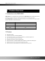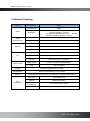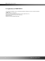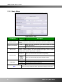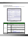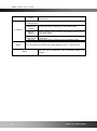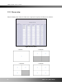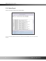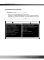
1
ONSIP OD101 User’s Guide ONSIP OD101 ` 1 Rev. 1.11 (Jun. 2013) ONSIP OD101 User’s Guide Date Rev No rd 1.0 1.11 Apr. 3 , 2013 th Jun 6 , 2013 Description Document creation Text revision ` 2 Rev. 1.11 (Jun. 2013) ONSIP OD101 User’s Guide Table of Contents 1. Product Overview ............................................................................................................................ 4 2. 1.1 Introduction to the ONSIP OD101 ............................................................................................. 4 1.2 Features ..................................................................................................................................... 4 1.3 Network Topology ...................................................................................................................... 5 1.4. Applications of ONSIP OD101 .................................................................................................. 6 Operating Instructions ..................................................................................................................... 7 3. 2.1 Package Contents ...................................................................................................................... 7 2.2. Product Preview ........................................................................................................................ 8 2.3. Physical description .................................................................................................................. 9 2.4. Functional Description ............................................................................................................ 10 Getting Started ............................................................................................................................... 12 4. 3.1. PC Requirement ..................................................................................................................... 12 3.2. IP address configuration ......................................................................................................... 13 3.3. Administration Tool configuration ............................................................................................ 15 Trouble Shooting ........................................................................................................................... 28 4.1. No power is applied ................................................................................................................ 28 4.2. Cannot connect to the Video .................................................................................................. 29 4.3. Technical Assistance ............................................................................................................... 30 ` 3 Rev. 1.11 (Jun. 2013) ONSIP OD101 User’s Guide 1. Product Overview 1.1 Introduction to the ONSIP OD101 ONSIP OD101 is an embedded network video decoder. ONSIP OD101 takes a digital signal (sources provide by IP camera or DVS) from a network, and converts it to an analog video signal. When ONSIP OD101 is connected to more than one camera, it can cycle between the images provide by them. This function is called “Poll function”. Video Resolution Yes/No D1 Yes CIF Yes HalfD1 Yes QCIF Yes VGA Yes Table 1-1 Video resolution support by ONSIP OD101 1.2 Features Decoding for H.264 Small size, low power, convenient installation PC-independent operation, high stability and efficiency, robustness against virus High video quality and resolution, high fidelity Automatic reconnection in case of network failure Strong Poll function, 32 targets available and accessible to configure each stalling time OSD presents the name of the destination target while polling Status information, high availability of the working state from every device ` 4 Rev. 1.11 (Jun. 2013) ONSIP OD101 User’s Guide 1.3 Network Topology Category Sub-Category Details Compression H.264 Video Resolution Audio (Bi-directional) Network I/O NTSC (30 frames/sec Max.) : 704x480, 640x480, 704x240, 352x240, 176x112 PAL/SECAM (25 frames/sec Max.) : 704x576, 640x480, 704x288, 352x288, 176x144 Up PCM 64 Kbps Down ADPCM 32 Kbps (G.726) Interface RJ-45, 10/100 Mbps, PoE (802.3af) Access network Static, DHCP, PPP/PPPoE Application IPv4, TCP/IP, ARP, DHCP, RTSP RS-485 Connection of PTZ controller Mic/Line In 1 V p-p output for amplified speaker Line Out For temporal use in installation CVBS output Power over Ethernet (IEEE802.3af) PoE 12V DC adapter Power Supply Upgrade Firmware upgrade over IP network Administration Remote administration over IP network Security ID and Password protection and IP filtering for restricting administrative Time management Sync to PC Synchronize to PC Manual Manual time setting Internet Time Server Synchronize to Time Server DLS Daylight Savings ` 5 Rev. 1.11 (Jun. 2013) ONSIP OD101 User’s Guide 1.4. Applications of ONSIP OD101 IP surveillance (buildings, stores, manufacturing facilities, parking lots, banks, government facilities, military, etc.. Real time Internet broadcasting Remote monitoring (hospitals, kindergartens, traffic, public areas, etc..) Teleconference (Bi-directional audio conference) Remote Learning Weather and environmental observation ` 6 Rev. 1.11 (Jun. 2013) ONSIP OD101 User’s Guide 2. Operating Instructions 2.1 Package Contents Open the package and check if you have the followings: Contents Description ONSIP OD101 ONSIP OD101 main unit CD Software & User‟s Guide Quick Reference Guide Remarks Quick installation guide ` 7 Rev. 1.11 (Jun. 2013) ONSIP OD101 User’s Guide 2.2. Product Preview ONSIP OD101 ONSIP-Installer H.264 Decoder PC software to allocate an IP address ` 8 Rev. 1.11 (Jun. 2013) ONSIP OD101 User’s Guide 2.3. Physical description 2.3.1. External View Figure 2-1. External view of ONSIP OD101 2.3.1. Front and Rear Figure 2-2. Front Figure 2-3. Rear ` 9 Rev. 1.11 (Jun. 2013) ONSIP OD101 User’s Guide 2.4. Functional Description Category Content RJ-45 PoE 12VDC input Adapter Video output CVBS In Standard PoE (IEEE802.3af) Max. 5W RS-485 Master 10/100Base-T 0.5A ~ 2.5A BNC Line Level (1Vpk) and micro phone Audio Out Misc. Configuration in administration tool Line Level (1Vpk) PTZ connection Terminated 100Base-T 100Mbps Ethernet connector (RJ-45) with PoE standard (802.3af). 2 LEDs on the Ethernet connector show the status of Decoder as the following: - Status LED (Dual Color - Red/Green) : It will be lit in green or red depending on the status. Green : Green color indicates that the product is in normal operation mode. Continuous green indicates that data transmission is possible. Blinking green means that someone is connected to ONSIP OD101. Red : Continuous or blinking red indicates that hardware is in abnormal condition. Red/Green LED will be lit with red momentarily and it will be lit with green after a while when power is applied into Decoder. - LINK/LAN LED (Orange) It will be lit with orange color when network cabling is all right. Blinking orange color indicates that normal data transmission is under way. Off state indicates that there is trouble with the network connection. DC 12V: Power input for supplying 12V DC power. Caution: If ONSIP OD101 is powered by PoE, do not plug in DC Jack with active DC power into DC power connector. Video output (CVBS) Video output from IP camera video. Audio in (MIC/LINE IN ) Connect external audio source or microphone. Audio out (Line Out) Connect speakers with built in amplifier. Audio from remote site is output through Line out in bidirectional audio mode. ` 10 Rev. 1.11 (Jun. 2013) ONSIP OD101 User’s Guide Factory Default Switch A switch provided for returning the product to factory default state. Press the switch for a few seconds while power is applied. Figure 2-5. Factory Default Switch Restoring the factory default will erase all settings. ` 11 Rev. 1.11 (Jun. 2013) ONSIP OD101 User’s Guide 3. Getting Started 3.1. PC Requirement First of all, you should set up the ONSIP OD101 such as IP address using the ONSIP installer software and administration tool using Internet Explorer. Minimum requirement of the PC is described below: Recommended CPU Pentium III or above Main Memory 512MB or above Operating System * Remark Windows XP Web Browser Internet Explorer 6.0 or above Network 100 Base-T Ethernet * Operating Systems supported: Windows 2000 Professional, Windows XP / Vista / 7 ` 12 Rev. 1.11 (Jun. 2013) ONSIP OD101 User’s Guide 3.2. IP address configuration 1. Connect PC and ONSIP OD101 to network. 1) Prepare a PC to run programs for the installation and video connection (PC is needed to assign IP address to ONSIP OD101) 2) In the case of using PoE, connect the PC and ONSIP OD101 to the network using one of the following ways. If your LAN Switch does not support standard PoE, connect ONSIP OD101 as shown in dotted line in Figure 3-1. The DC power is applied through DC adapter. DC adapter LAN switch CVBS/ Monitor LAN switch with standard POE (802.3af) Figure 3-1. Power and network connection 2. Install “ONSIP installer” and set IP parameters on ONSIP OD101 Insert the CD provided with product into the PC. Install ONSIP Installer ONSIP installer Ver. 3.0.1 or later is needed in the configuration. Follow the sequence below for setting the IP parameter i) Run ONSIP installer > Select Network Adapter >OK ii) Click ① in ONSIP installer window.> Double click on ② > Fill in ④ > make a selection in ⑤ > Fill the parameters in ⑥ iii) Click on ⑨ to apply the settings. iv) You can connect to admin page by clicking on ⑩. ` 13 Rev. 1.11 (Jun. 2013) ONSIP OD101 User’s Guide 3 1 2 9 10 5 4 7 6 8 Figure 3-2. IP installer Click on the field in ③ for sorting and rearranging the list. Select network mode that best suits from the drop down list in ⑤. You can choose either Static or ADSL and Auto (DHCP), respectively. If ADSL and Auto are selected, the fields in ⑥ is deactivated. In case of ADSL, fill the User Name and Password in ⑧ with the values provided by your ISP. ` 14 Rev. 1.11 (Jun. 2013) ONSIP OD101 User’s Guide 3.3. Administration Tool configuration There is a way of connecting to the Decoder admin mode. Type in the connection address of the product in the address field of the Internet Explorer as followings: http://[IP address of the product], Example: http://172.16.43.244 Default ID and Passwork are “admin” and “1234”. Figure 3-3. Log-in window ` 15 Rev. 1.11 (Jun. 2013) ONSIP OD101 User’s Guide 3.3.1. Basic Setup Figure 3-4 Basic Setup Field/Button System name Audio input selection Video format Sub Field Description /Button Input, edit and save the name of ONSIP OD101 here (support input English, letter and character). ONSIP OD101 name will be shown in the [Search List] window. When you use microphone, you should check the radio Mic button and volume. Line-in: When you use external audio signal, check it. Choose different output standard to matching different monitor. If user‟s monitor is NTSC monitor, he should choose the output format “NTSC”. (ONSIP OD101 default output format is “NTSC”) Sequence Viewing mode OSD setup Save Single / Default group When you want to see each channel sequentially. When you want to see group such as split screens. OSD You can select Enable or Disable. Time You can select Camera or Decoder. Alarm You can select Enable or Disable. Save the set-up parameters when parameters settings are finished. ` 16 Rev. 1.11 (Jun. 2013) ONSIP OD101 User’s Guide 3.3.2. Network Configuration Setup the network parameters appropriately in accordance with your network environment. Many of the parameters in this page are same as those set up by “ONSIP-Installer”. Figure 3-5 Network Configuration Field/Button IP Assign Type Sub Field Description /Button The network types supported by the products are LAN(fixed IP), PPPoE, and DHCP(automatic IP allocation) When the network environment is fixed IP, select „LAN‟ in the network type, and input the IP address, Subnet Mask, Static IP Setup Gateway, DNS1 and DNS2. Ask your network administrator or ISP for the information. DNS2 is used when DNS1 does not work. When the network environment is PPPoE and IP address is assigned automatically, select „PPPoE‟ in the network type. PPPoE Setup Next, fill in the „User Name‟ and „Password‟ fields with the values given by your ISP. DHCP Port Change Setup When the DHCP server assigns IP address automatically, select „DHCP‟ in the network type. Select this mode in case of Cable Modem. Refer to [ONSIP-installer user’s guide] for “Host name and domain for Cable Modem Refer to [ONSIP-installer user’s guide] for “Clone MAC” Clone MAC Each port should have a number below 65535. ` 17 Rev. 1.11 (Jun. 2013) ONSIP OD101 User’s Guide HTTP HTTP port is used for the connection to the admin page. Default is 80. You can restrict the access to the admin page from IP addresses beyond certain IP address range. Restrict Administrator Access Check at this box to restrict log on to the admin page. IP Filtering DDNS Base IP Address Input IP address of the PC which is intended to be used for log on to admin mode. Using External SMTP Server Use TLS If you are using external mail server, fill in the fields with proper parameters. Check at this box to use SSL log on to the SMTP server. You can register the product to the Speco DDNS server for a name service. Save Save the set-up parameters when parameters settings are finished. ` 18 Rev. 1.11 (Jun. 2013) ONSIP OD101 User’s Guide 3.3.3. Group setup Setup the display group. Group can setup up to 16 groups and a group can setup up to 4 channels. Figure 3-6 Group Setup 1 channel 3 channels 2 channels 4 channels ` 19 Rev. 1.11 (Jun. 2013) ONSIP OD101 User’s Guide Field/Button Group Apply / Delete Sub Field /Button Description Delete Deletion of all channel parameters Index Group number Channel 1~4 Assignment of each channel During Waiting time from 10 sec. to 120 sec. Enable You can select Enable or Disable. Save the setup parameters or delete selected check-box on Delete ` 20 Rev. 1.11 (Jun. 2013) ONSIP OD101 User’s Guide 3.3.4. Session setup Figure 3-7 Session Setup Field/Button Sub Field /Button Delete Deletion of all channel parameters. Index Number of camera and video server lists. Name Session Address Port Channel ID/Password Apply / Delete Description Input the name. IP address and domain name of encoder. Default list table are blank, support input Internet IP, LAN IP and Internet domain name. (Suppose an encoder domain name, the address blank must input like this “ipcam.vicp.net”, do NOT input the “http://”). Input the http port number. Select the channel. IP camera and video server is channel 1. In case of 4 channels video server, select desired channel. Input the ID and Password. Default ID/PW is admin/1234. Save the setup parameters or delete selected check-box on Delete. Connecting decoders target list: ` 21 Rev. 1.11 (Jun. 2013) ONSIP OD101 User’s Guide 3.3.5. User Admin & Time Setup Figure 3-8 User admin. & Time setup Field/Button User Administration Time Setup SAVE Sub Field /Button Description Administrator Username Admin ID. Default ID is “admin” Administrator password : Administrator Confirm Password Admin password. The default password is “1234”. Current Time It shows you the current time kept in the product. Synchronize with an Internet Time Server Synchronize With this Computer Time Set Manually Synchronize the time kept in the product with the time kept in time server on the internet at the right. When the time server is out of the reach from the product, you can assign time server by filling in “Specific Time Server” field. Enter the password once more to confirm the password. Synchronize the time kept in the product with the time in the PC. Set the time manually. Fill in the fields with desired formats. Save the set up parameters ` 22 Rev. 1.11 (Jun. 2013) ONSIP OD101 User’s Guide If you lost Administrator’s ID and password, the only means of recovery is to reset the settings to factory default, but then you lose your previous settings. ` 23 Rev. 1.11 (Jun. 2013) ONSIP OD101 User’s Guide 3.3.6. PTZ setup This is the setup page for PTZ controller. Figure 3-9 PTZ Setup Field/Button Sub Field /Button PTZ controller Selection Description Choose the PTZ controller. Delete Button SAVE PTZ baud Rate Click on this button to delete. (Do not delete the default model.) Save the set-up parameters when PTZ controller setting is finished. Select this Baud rate to set the PTZ controller. SAVE Save the set-up parameters when baud rate setting is finished. ` 24 Rev. 1.11 (Jun. 2013) ONSIP OD101 User’s Guide 3.3.7. Upgrade & Reset You can upgrade the device via the IP network. Figure 3-10 Upgrade & Reset Contents of the upgradable system component should be downloaded from ONSIP‟s home page before the system upgrade is performed. Field/Button Manual Upgrade Add PTZ File Sub Field Description /Button Upgrade the system manually. Upgrade the system software installed on the product via System S/W network. System software needed for the upgrade can Upgrade downloaded from ONSIP‟s home page. Upgrade the boot loader installed on the product via Bootloader network. Bootloader needed for the upgrade can Upgrade downloaded from ONSIP‟s home page. the be the be Upgrade the PTZ script file for adding new PTZ controller. Factory Default Setting Re-initialize the product to factory default state. By checking on a Radio button “Preserve Network Configuration”, you can preserve the parameters for the network. Checking on “All”, will return all the parameters to factory default state. System Restart Once all the values are set to factory default state, the product should be set-up again using IP-Installer. Perform remote reset by clicking on the “CONFIRM” button. [Important] To apply upgraded contents, you should perform System Restart. All previous connections will be disconnected upon reset. ` 25 Rev. 1.11 (Jun. 2013) ONSIP OD101 User’s Guide Device does not resume the connections and the users must re-connect to the product manually. Upgrading the device. Unless otherwise instructed, the owners of the device are recommended to upgrade the system when upgraded firmware is released using manual upgrade procedure. Followings are the procedure to apply for the manual upgrade 1) Save the upgrade system software to your PC. Upgrade software can be downloaded from ONSIP‟s home page or provided in CD. 2) Connect to the product in admin mode and select “Update & Reset” menu. 3) Click "Browse..." to find the files you want to use for upgrade. This will open a "Choose file" dialogue window. The file extension is “ief” for the case of system firmware. 4) When you've found the file, click "Open." This will select the file and close the "Choose file" dialogue window. 5) Click the "INSTALL" button. An alert message box will pop up. Click “OK” button then it will start uploading the file. This may take some time. 6) Upgrade completion message will appear after the system upgrade has been completed. 7) Reboot device by performing “System Restart”. 8) After rebooting, log on to the product in admin mode again and click the “Status Report”. 9) Check the version number and release date of the firmware. You can download system software of the device from ONSIP‟s homepage. http://www.ONSIP.com Once the system is reset to the factory default state by system reset of the administrator, all the connection of the users might be disconnected. Since the connection is not recovered automatically, users should set up the connection manually with new connection information. ` 26 Rev. 1.11 (Jun. 2013) ONSIP OD101 User’s Guide 3.3.8. Status Report It shows you system records since the system started. You can check the problems as well as the versions and event status of the whole system and modules. ` 27 Rev. 1.11 (Jun. 2013) ONSIP OD101 User’s Guide 4. Troubleshooting 4.1. No power is applied In case of Standard PoE (Power over Ethernet) Power supply through standard PoE is possible only when the following conditions are met. 1. Standard PoE is supported on the product. 2. The LAN switch supports standard PoE. Make sure that both the product and the LAN switch support standard PoE (IEEE 802.3af) In case of DC adapter If PoE is not applied, the power and network connection should be made through separate cables. It is recommended to use DC adapter supplied by ONSIP for the feeding of the power. In case of replacing the DC power supply, make sure that the power supply meets with the power requirement of the product to prevent damage or malfunction. ` 28 Rev. 1.11 (Jun. 2013) ONSIP OD101 User’s Guide 4.2. Cannot connect to the Video Check the status of the network connection through PING test. Try the following on your PC : - - Start > Run > Cmd > Ping IP address (Ex : Ping 172.16.42.51) If “Reply from ~” message is returned ( 1 in the figure below), the network connection is in normal state. Try connection to the video again. If the problem persists, or refer to other trouble shooting notes. If “Request timed out” message is returned. ( 2 in the figure below), the network connection or network setting is not in normal state. Check the network cable and settings. 1 2 ` 29 Rev. 1.11 (Jun. 2013) ONSIP OD101 User’s Guide 4.3. Technical Assistance If you need any technical assistance, please contact your dealer. For immediate service please provide the following information. 1. Model name 2. MAC address and Registration number 3. Purchase date 4. Description of the problem 5. Error message ` 30 Rev. 1.11 (Jun. 2013)