1
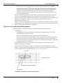
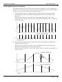
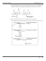
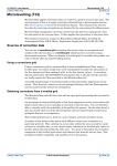
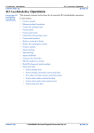
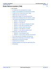
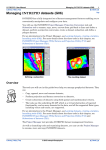
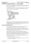
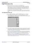
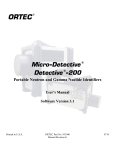
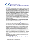
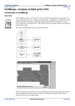
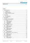
INTREPID User Manual
Library | Help | Top
Decorrugation (T32)
1
| Back |
Decorrugation (T32)
Top
After you have corrected, tie-line levelled and gridded your survey data, some
residual line-to-line errors may still be visible. These may appear as streaks or
corrugations in your grid display. They are sometimes referred to as levelling
artifacts, or levelling ‘busts’. We describe them in detail in the section following.
INTREPID's Decorrugation tool removes these features from the grid, and
Microlevelling (See Microlevelling (T33)) applies the grid corrections back to your line
dataset.
This method is based on a paper by Brian Minty (Simple Micro-Levelling for
Aeromagnetic Data, B.R.S. Minty, Exploration Geophysics (1991), 22, 591-592)
Decorrugation theory
Sources of corrugations
Corrugations (levelling artifacts) in your gridded data are caused by line-to-line
levelling errors in your line data. These are generally caused by conditions
encountered during acquisition of airborne survey data, and/or errors in conventional
tie-line levelling. (SeeLine correction and tie levelling (T30)). For example,
•
Levelling is required to remove the effects of time variations in the Earth’s
magnetic field. There may not be enough crossover points in the dataset to
adequately model and correct for this variation.
•
The measured position of a crossover point of an acquisition and tie line may not
be accurate. If an error arises here, it may introduce an error covering a region
that extends one line spacing in each direction. The dimensions of this region
would therefore be twice the tie line separation by twice the acquisition line
separation. Since the introduction of Global Positioning Satellites the likelihood
of this type of error has lessened considerably.
•
There may be diurnal fluctuations not accurately measured at the base station
because they are localised and/or have a steep gradient. These could affect a
number of measurements along an acquisition line and be only partly corrected
for by tie line levelling.
•
Aircraft ground clearance varitaions cause line-to-line errors, and these
variations are generally difficult to properly correct for.
Whilst these residual levelling errors are usually small, when you use image
processing and display enhancement techniques, and compute derivatives of the
data, they become more obvious and reduce the quality of your images.
In airborne gamma ray spectrometric surveying, the following conditions can
cause line-to-line errors in the data:
•
There is a period of rain during a traverse. When the aircraft flies through rain,
moisture in the air and ground attenuates the gamma rays thus yielding a lower
count rate.
•
The aircraft flies across land where it has recently rained, perhaps where a
thunderstorm has passed. In this case:
•
Library | Help | Top
The increased moisture content of the soil attenuates the gamma rays thus
yielding a generally lower count rate.
© 2012 Intrepid Geophysics
| Back |
INTREPID User Manual
Library | Help | Top
•
•
Decorrugation (T32)
2
| Back |
There can be an increased surface concentration of radioactive daughter
elements of airborne 222Ra. These daughter products attach themselves to
dust particles in the atmosphere. Rain precipitates them onto the Earth's
surface. This phenomenon increases the count rates in the TC and U
channels. Because of the short half lives involved, anomalous activity will
only last about 6 hours.
The aircraft flies through a 'radon cloud'. Under still air conditions, inversion
layers over topographic depressions and lakes often trap radon close to the
ground. Radon clouds will increase the count rate primarily in the Uranium and
Total Count channels. These 'radon clouds' disperse during the day as
atmospheric mixing occurs.
When a survey is interrupted at the end of a working day, radon clouds may have
largely dispersed. The following morning, as the survey recommences at the same
place, radon clouds may have reappeared.
Types of error removed by Decorrugation
Decorrugation can remove anomalies with the following characteristics:
•
Wavelength
•
Perpendicular to the acquisition line direction—approximately twice the
acquisition line spacing or less.
•
In acquisition line direction, at least twice tie line spacing.
These are minimum wavelengths likely for corrugations arising from causes
listed in the previous section. Shorter wavelengths in the acquisition line
direction or longer wavelengths in the tie line direction would give a high risk
of eliminating real anomalies.
•
A symmetrical waveform. We make this assumption in order to keep the
Decorrugation process simple.
•
A relatively small dynamic range. Corrugations are by definition very small
errors. A large magnitude anomaly must be real or have some other cause besides
those suggested for corrugations (See Sources of corrugations).
Tie Lines
Acquisition Lines
Levelling error at this crossover
Corrugation
Corrugation arising from a tie line levelling error
Library | Help | Top
© 2012 Intrepid Geophysics
| Back |
INTREPID User Manual
Library | Help | Top
Decorrugation (T32)
3
| Back |
Decorrugation general technique
To simplify the process, one of the grid axes must be parallel to the acquisition line
direction. You can then remove the corrugations by applying one dimensional filters
in turn to the rows and columns of the grid as follows:
1
Call the original grid 'A'. Apply a high pass filter (extract data with a short
wavelength) to grid A in the direction perpendicular to the acquisition line
direction.
This removes all data except that with a wavelength (perpendicular to the
acquisition line direction) of twice the acquisition line spacing or less. Store the
result in grid 'B'.
Levelled and gridded data
0
Results of high pass filter
0
Acquisition lines
2
Apply a low pass filter (extract data with a long wavelength) to grid B in the
acquisition line direction.
This removes all data except that with a wavelength (in the acquisition line
direction) greater than twice the tie line spacing.
Store the result in grid 'C'. Grid C should now contain only the corrugations we
wish to remove.
Levelled and gridded data
0
Results of low pass filter
0
Tie lines
Library | Help | Top
© 2012 Intrepid Geophysics
| Back |
INTREPID User Manual
Library | Help | Top
3
Decorrugation (T32)
4
| Back |
Restrict the dynamic range of grid C by setting all values so that they fall between
two limits defined by you. Set any values beyond the limits to equal the limits
themselves. Grid C now represents residual errors (corrections to be made).
0
Data with restricted
dynamic range
Original data
4
Subtract grid C from grid A to give the grid without Corrugations.
The following diagram illustrates the two filter steps in the decorrugation process
Anomalies before identifying
corrugations
Anomalies after low pass filter
Low pass filter
Identified corrugations after
high pass filter
High pass filter
Library | Help | Top
© 2012 Intrepid Geophysics
| Back |
INTREPID User Manual
Library | Help | Top
Decorrugation (T32)
5
| Back |
Decorrugation—practical methods
We require a set of filters that removes all errors but at the same time excludes as
many real anomalies as possible. To avoid removing real anomalies, we extract
residual errors with the longest possible wavelength along the acquisition lines, the
shortest wavelength perpendicular to the lines and the smallest dynamic range that
still produces a well levelled grid. In practice you will need to use some trial and
error until you achieve a satisfactory result.
Decorrugation is our recommended method of removing Corrugations. Like any other
similar method, it is far from perfect and you must use it under your own close
supervision. Some other filtering techniques, such as spectral domain filters, may
work just as well. No matter which method you use, you can still use the resulting
grid with Microlevelling to level your original line data.
Note that you must still perform conventional tie line levelling. The Decorrugation
technique can only correct small residual levelling errors. The data must be
reasonably level prior to the gridding process.
If you have real anomalies that may be removed by Decorrugation, you should use a
subsection 'mask' to specify parts of the grid that should not be filtered. You should
truncate residuals (corrections) that are obviously too large to be valid.
Two types of filter are available. Each has imperfections (See Potential limitations of
Decorrugation). You can select the type of filter and use them in tandem to minimise
their deficiencies. The filter types available are the Naudy non-linear filter18 and the
Fuller hanned band pass convolution filter.29.
Potential limitations of Decorrugation
•
The technique could well eliminate real anomalies if they have the qualifying
characteristics for Decorrugation.
•
If there are adjacent errors of similar magnitude, Decorrugation will only detect
the differences between these errors.
The two filter techniques each have their own problems:
•
The Naudy filter is not a true frequency filter. It operates by detecting anomalies
of wavelength shorter than the defined cutoff. Such anomalies are then removed
by extrapolating over them from data values that bound them. We have found
that
•
The anomaly-detecting algorithm is not foolproof and some anomalies may not
be removed.
•
The extrapolation algorithm may introduce data of frequency beyond the
intended cutoff.
1.8 Henri Dreyer and Henri Naudy, Non-Linear Filtering Applied to Aeromagnetic
Profiles, Geophysical Prospecting, 16(2), June 1968.
2.9D.C. Fraser, B.D. Fuller and S.H. Ward, Some Numerical Techniques for Application in
Mining Exploration, Geophysics, vol. XXXI, NO. 6, December, 1966.
Library | Help | Top
© 2012 Intrepid Geophysics
| Back |
INTREPID User Manual
Library | Help | Top
•
Decorrugation (T32)
6
| Back |
The Fuller hanned band pass convolution filter technique is less than perfect
since the response of the filter at the cutoff wavelength is not abrupt. For low
pass filters it acts as a smoothing operator where the area under the profile
remains constant. We have found that
•
Leakage occurs around anomalies of moderate amplitude that have
wavelengths comparable to the length of the cutoff wavelength of the low pass
filter.
•
When high amplitude short wavelength anomalies occur the magnitude of the
filtered values about the anomaly are raised giving a streak effect exactly like
the anomalies that are to be removed.
•
For very long wavelengths, program efficiency requires that the number of
convolution coefficients be restricted, with the data effectively being
subsampled. This results in high frequency noise being introduced at a
wavelength equal to the subsampled interval.
For both types of filters, at the edge of the grid the data must be extrapolated to allow
filtered values to be determined up to the boundary. These extrapolation techniques
do not always provide desirable filtered results.
The Decorrugation tool
The Decorrugation tool is a two dimensional grid filtering program, specifically
designed to remove anomalies elongate in the line direction.
If required, you can use the INTREPID subsection facility (See Subsections of
datasets (T21)) to specify parts of the grid (windows) that should not be filtered.
INTREPID will set corrections within the windows to zero and linearly extrapolate
the values at the edge of the window to zero over an interval that you specify.
You can restrict the dynamic range of the residuals (corrections) within two bounds.
Since the residuals (corrections) will always have an average value of zero, these
bounds can be ±n, where the value n is chosen to be close to the maximum size of the
expected corrections. In this manner you can truncate those residuals that are
obviously too large to be valid corrections.
The output grid can be either a filtered (levelled) version of the input grid or a grid of
the residuals (corrections) after filtering. Normally you would produce a levelled
output grid for inspection and visualisation processes, but a grid of corrections for
input to the Microlevelling tool (See Microlevelling (T33)).
>> To use Decorrugation with the INTREPID graphic user interface
Library | Help | Top
1
Ensure that you have already levelled, gridded and subsectioned your data as
required.
2
Choose Decorrugate from the Level menu in the Project Manager, or use the
command decor.exe. INTREPID displays the Decorrugation window
3
If you have previously prepared file specifications and parameter settings for
Decorrugation, load the corresponding task specification file using Load Options
from the File menu. (See Specifying input and output files for detailed
instructions.) If all of the specifications are correct in this file, go to step 8. If you
wish to modify any settings, carry out the following steps as required.
© 2012 Intrepid Geophysics
| Back |
INTREPID User Manual
Library | Help | Top
Decorrugation (T32)
7
| Back |
4
Specify the grid dataset to be processed. Use Open Input Grid from the File
menu. (See Specifying input and output files for detailed instructions.)
INTREPID displays the dataset in the Decorrugation window.
5
Specify the output grid dataset to be created with the results of the process. Use
Specify Output Grid from the File menu. (See Specifying input and output files
for detailed instructions.)
6
Specify the parameters and filter type for the Decorrugation using Parameters
and Type from the Filters menu (See Setting Decorrugation filter parameters and
Choosing the Decorrugation filter type for details).
7
Specify whether you require the output file to be a levelled (corrected) grid or a
grid dataset containing the corrections. Choose the corresponding option from
the Grid Output menu. (See Decorrugation output grid contents for more
information.)
8
When you have made specifications and settings according to your requirements,
choose Apply. INTREPID will perform the corrections and display the new data
in the Decorrugation window as it is produced.
When the process has finished you can zoom (enlarge an area of the display) and
pan (examine different regions while enlarged) (See Zooming and panning the
grid display for details).
Library | Help | Top
© 2012 Intrepid Geophysics
| Back |
INTREPID User Manual
Library | Help | Top
9
Decorrugation (T32)
8
| Back |
If you wish to record the specifications for this process in a .job file in order to
repeat a similar task later or for some other reason, use Save Options from the file
menu. (See Specifying input and output files for detailed instructions.)
10 If you wish to repeat the process, repeat steps 3–8, varying the parameters and/or
data files as required.
11 To exit from Decorrugation, choose Quit from the File menu.
___
To view the current set of specifications choose Show from the Decorrugation window.
INTREPID displays them in a separate report window. See Displaying options and
using task specification files for details and an example of a set of specifications.
After using Decorrugation you can carry out a more detailed inspection of the filtered
grid using an INTREPID visualisation tool (See Visualisation (T26)).
You can view Help information by choosing options from the Help menu (See Help).
You can execute Decorrugation as a batch task using a task specification (.job) file
that you have previously prepared. See Displaying options and using task
specification files for details.
Zooming and panning the grid display
You can enlarge and reduce the display (zoom in and out) and view different parts of
it (pan).
>> To zoom in and out (enlarge/reduce)
To zoom in (enlarge the display) choose Zoom In at the right edge of the
Decorrugation window. Each time you choose this button, INTREPID will enlarge
the display by one step.
To zoom out (reduce the display) choose Zoom Out at the right edge of the
Decorrugation window. Each time you choose this button, INTREPID will reduce
the display by one step.
Library | Help | Top
© 2012 Intrepid Geophysics
| Back |
INTREPID User Manual
Library | Help | Top
Decorrugation (T32)
9
| Back |
>> To zoom in on a selected area of the display
Choose Zoom Area, then hold down the left mouse button and drag diagonally (corner
to corner) across the area that you wish to enlarge. INTREPID will enlarge the
selected region to fill the display area of the window.
>> To pan the display (view different parts)
The Pan/zoom indicator at the right of the Decorrugation window in the centre
consists of a small square within a larger square. The large square represents the
whole display and the small square the part visible on the screen. When you drag the
small square to a different part of the large square INTREPID shows the
corresponding part of the display.
If you have zoomed out to view the whole display, the small square may occupy the
whole of the large square and may not be visible.
Specifying input and output files
To use Decorrugation, you will need to specify the grid dataset to be corrected and the
grid dataset for saving the corrections. Choose the options as required from the File
menu.
In each case INTREPID displays an Open or Save As dialog box. Use the directory
and file selector to locate the file you require. (See "Specifying input and output files"
in Introduction to INTREPID (R02) for information about specifying files).
Open Input Grid Use this option to specify the grid to be filtered. INTREPID will
open and display it in the Decorrugation window.
Specify Output Grid Use this option to specify the name for the grid dataset you
are creating with this process.
Load Options If you wish to use an existing task specification file to specify the
Decorrugation process, use this option to specify the task specification file
required. INTREPID will load the file and use its contents to set all of the
parameters for the Decorrugation process. (See Displaying options and using task
specification files for more information).
Save Options If you wish to save the current Decorrugation file specifications and
parameter settings as an task specification file, use this option to specify the
filename and save the file. (See Displaying options and using task specification
files for more information).
Library | Help | Top
© 2012 Intrepid Geophysics
| Back |
INTREPID User Manual
Library | Help | Top
Decorrugation (T32)
10
| Back |
Using Decorrugation for 'oblique' line datasets
If the purpose of using this tool is to decorrugate an 'oblique' line dataset (one with
traverse lines that are not oriented North–South or East–West) you must have
produced an input grid with either its columns or rows parallel to the traverse lines of
the line dataset being corrected (i.e., a rotated grid).
The Gridding tool has facilities for this process. See "Producing a rotated grid" in Old
Gridding (T22) for instructions.
Note: If you correctly use a rotated grid as the input grid for Decorrugation, the
output grid will be ready to input to the Microlevelling tool without further
adjustment. Do not rotate the output (corrections or levelled) grid before using it
with Microlevelling. See Microlevelling (T33) for further information.
Choosing the Decorrugation filter type
Use High Pass Type from the Filter menu to define the type of filter to use
perpendicular to the acquisition line direction. Use Low Pass Type from the Filter
menu to define the type of filter to use in the acquisition line direction.
Naudy Use the Naudy filter.
Naudy–Fuller Use Naudy and Fuller filters in tandem. For the low pass filter
INTREPID will apply the Naudy filter first followed by a Fuller filter. This gives
the best results but takes longer.
Fuller Use the Fuller filter.
Smoothed Fuller Use the Fuller filter. INTREPID uses subsampling of the data for
low pass filters. In this case a secondary Fuller filter will remove any introduced
high frequency noise.
We recommend that you use a Naudy filter for the high pass filter and a Smoothed
Fuller filter for the low pass filter.
Library | Help | Top
© 2012 Intrepid Geophysics
| Back |
INTREPID User Manual
Library | Help | Top
Decorrugation (T32)
11
| Back |
Filter parameters
Window size (wavelength) This parameter corresponds to the length and width of
the streaks you are removing. See Setting Decorrugation filter parameters for
instructions.
(High Pass Tolerance) (First (high pass) filter) In normal interactive mode the
Naudy filter tolerance for the first (high pass) filter is set to 0.01 . This is
satisfactory for magnetic data, but too high for such data as a vertical derivative
grid. If you use the Decorrugation tool with a task specification file in interactive
or batch mode you can specify a different tolerance by adding the line
HighPassTolerance = to the parameters block. See Displaying options and
using task specification files for details.
See "Fuller filter" in INTREPID spatial and time domain filters and transformations
(R13) and "Naudy filter" in INTREPID spatial and time domain filters and
transformations (R13) for general information about the filters and their parameters.
Setting Decorrugation filter parameters
To set the parameters, choose Parameters from the Filters menu.
INTREPID displays the Decorrugation parameters dialog box.
Set the parameters according to your requirements then choose OK. Specify
wavelengths in metres.
. .Mean Streak Length The minimum length of an anomaly (parallel to the
acquisition line direction) that INTREPID will recognise as a corrugation and
remove. Minimum streak length is usually twice the tie line spacing. INTREPID
will only treat anomalies longer than this as potential corrugations.
INTREPID uses this parameter in the low pass filter. It corresponds to the
window size parameter for the Fuller and/or Naudy filter used in the process. See
"Fuller filter" in INTREPID spatial and time domain filters and transformations
(R13) and "Naudy filter" in INTREPID spatial and time domain filters and
transformations (R13) for further information.
Library | Help | Top
© 2012 Intrepid Geophysics
| Back |
INTREPID User Manual
Library | Help | Top
Decorrugation (T32)
12
| Back |
Streak width The maximum width of an anomaly (perpendicular to the acquisition
line direction) that INTREPID will recognise it as a corrugation and remove
(usually twice the acquisition line spacing). INTREPID will only treat anomalies
narrower than this as potential corrugations.
INTREPID uses this parameter in the high pass filter. It corresponds to the
window size parameter for the Fuller and/or Naudy filter used in the process. See
"Fuller filter" in INTREPID spatial and time domain filters and transformations
(R13) and "Naudy filter" in INTREPID spatial and time domain filters and
transformations (R13) for further information.
Minimum adjustment The minimum value for any detected correction. If
INTREPID finds any correction less than this minimum value, it will set the
correction for this cell equal to the minimum value. The minimum adjustment
typically has the same absolute value as the maximum adjustment (see below).
Maximum adjustment The maximum value for any detected correction. If
INTREPID finds any correction greater than this maximum value, it will set the
correction for this cell equal to the maximum value. The maximum adjustment
typically has the same absolute value as the minimum adjustment (see above).
Decorrugate along Columns / Rows Select the option corresponding to the
direction of the traverse lines that you used to produce the grid. See Using
Decorrugation for 'oblique' line datasets for important notes if the source traverse
lines for the grid were not oriented North–South or East–West.
Decorrugation output grid contents
Use the Grid output menu to specify whether the output grid should contain the
corrections to be made or the final corrected values.
You would normally produce levelled grids while you are arriving at ideal parameter
settings and filter choices. You can visually inspect this filtered grid to ensure that
unwanted streaks have been removed. Once you have determined the optimal filters,
you would produce a grid containing only the corrections to be made. This is the grid
for input to the Microlevelling tool (See Microlevelling (T33)).
Help
You can use the Help menu to display help text on the topics shown in the menu
illustration below.
Exit
To exit from Decorrugation choose Quit from the file menu.
Library | Help | Top
© 2012 Intrepid Geophysics
| Back |
INTREPID User Manual
Library | Help | Top
Decorrugation (T32)
13
| Back |
Displaying options and using task specification files
Displaying options
>> To display the current file specifications and parameter settings
Choose Show in the Decorrugation window. INTREPID displays the current options
in a separate report window.
Using task specification files
You can store sets of file specifications and parameter settings for Decorrugation in
task specification (.job) files.
>> To create a task specification file with the Decorrugation tool
1
Specify all files and parameters.
2
If possible, execute the task (choose Apply) to ensure that it will work.
3
Choose Save Options from the File menu. Specify a task specification file
(INTREPID will add the extension .job) INTREPID will create the file with the
settings current at the time of the Save Options operation.
For full instructions on creating and editing task specification files see INTREPID
task specification (.job) files (R06).
>> To use a task specification file in an interactive Decorrugation session
Load the task specification (.job) file (File menu, Load Options), modify any settings
as required, then choose Apply.
>> To use a task specification file for a batch mode Decorrugation task
Type the command decor.exe with the switch –batch followed by the name of the
task specification file.
For example, if you had a task specification file called surv329.job in the current
directory you would use the command
decor.exe –batch surv329.job
Library | Help | Top
© 2012 Intrepid Geophysics
| Back |
INTREPID User Manual
Library | Help | Top
Decorrugation (T32)
14
| Back |
Task specification file notes and example
Here is an example of a Decorrugation task specification file.
Process Begin
Name = decorrugate
Parameters Begin
HighPassFilter = "NAUDY"
LowPassFilter = "SMOOTHEDFULLER"
StreakLength = 5000.00
StreakWidth = 800.00
HighPassTolerance = .01
MinimumCorrection = –10.00
MaximumCorrection = 10.00
GridBand = –1
StrikeDirection = 90.00
CorrectionGrid = Yes
Parameters End
InputGrid = /disk1/grids/sp596_mag
OutputGrid = /disk1/grids/p596_corr
Process End
Notes
You can specify the tolerance for a high pass Naudy filter by adding the line
HighPassTolerance = to the parameters block as shown in the above example.
See "Naudy filter" in INTREPID spatial and time domain filters and transformations
(R13)for further information.
Library | Help | Top
© 2012 Intrepid Geophysics
| Back |
INTREPID User Manual
Library | Help | Top
Decorrugation (T32)
15
| Back |
Frequently asked questions
Q : I am having trouble finding the right decorrugation filter combination.
Can I run it more than once?
Yes, you can run Decorrugation multiple times with different filter settings. If you
output a levelled grid, each time you can apply different filter settings to remove
different shaped streaks from your data.
Library | Help | Top
© 2012 Intrepid Geophysics
| Back |