1
BLACK BOX Catalogue Ltd
The Source for Connectivity
MDU903
MDU904
RMU903
MDU903C
Data-Link Modem
TECHNICAL:
SALES:
FAX:
ADDRESS:
WEB:
(0118) 931 2233
(0118) 965 5100
(0118) 931 1727
15 Cradock Road, Reading, Berkshire RG2 0JT
www.blackbox.co.uk
Data-Link Modem
Notice
No part of this document may be reproduced, transmitted, copied out or translated without prior written consent of BLACK BOX
SA.
All rights reserved.
Copyright 1997, BLACK BOX June 97.
Foreword
This document describes how to set up the BLACK BOX MDU903/4 modem.
•=
•=
•=
•=
•=
•=
Chapter 1 is to familiarize the user with the operation of a modem.
Chapter 2 describes the installation.
Chapter 3 describes the most common uses of a modem.
Chapter 4 explains the operation of the modem security features and memories.
Chapter 5 provides technical characteristics.
Chapter 6 indicates how to solve operation problems.
Note to the reader
Users who are not familiar with the MDU903/4 modem operation, should read the first three chapters. Advanced users can
refer directly to chapter 4 to use the advanced functions of the modem. Whenever a problem arises, refer to chapter 6.
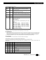
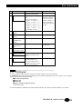
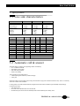
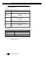
Product range
The MDU903/4 modem has various options:
•= Dial-up
•= Leased line
•= Group III fax
•= Stand alone or rack
•= LCD front panel
These different versions are summed up in the following table. The names in the first column will be used throughout the
manual to indicate when these options apply.
TECHNICAL: 0118 931 2233
3
Data-Link Modem
LCD version
Versions :
Stand alone version
Data-Link
Options :
MDU903
Optional
Optional
-
LCD
Leased Line
230VAC
48VDC
(*) 5VDC
RACK
Industrial
Data-Link
MDU904
Optional
Optional
-
Rackmount version
Rack
mount
MDU903C
Optional
Optional
RMU903
(*) Power supply 5V adaptator 230VAC
MDU903/4 features
The MDU903/4 is a modem for the professional user. It encompasses a number of features that place it above the rest. It
includes features such as:
•=
•=
•=
•=
•=
•=
•=
•=
•=
•=
Configuration through front panel LCD and key pad: for synchronous application, the MDU903/904 can be fully set up from
its user friendly front panel.
Busy-Out: Whenever modems are pooled, a faulty modem will lock-up the rest. The busy-out, standard in the BLACK BOX
modems lets the PBX pass onto the next modem without upsetting the system.
Line Quality Testing: The modem can test a line at every call. If it finds it below standard, it will hang-up and retry up to 5
times transparently to the user. This guarantees that you have the most reliable connection every time on any type of
infrastructure.
BERT: The modem can perform simple Bit Error Rate Tests between two BLACK BOX modems to qualify the digital
transmission of data.
ITU V.13: Half duplex operation.
10 User Configurations
UnAttended Automatic Dial Backup: If ever your Leased Line fails, the MDU903/4 will back-up onto the dial-up network.
Not only that, it will continue to monitor the Leased Line until it is operational and switch back automatically. This is called
Intelligent LookBack.
Password Security: To change configuration of the modem, 2 levels of password security are provided - User & Supervisor.
Connection Security: 4 levels of security are provided:
Answerback, i.e. where the far modem asks the calling modem for a password, transparently to the user.
Pass Through Access, i.e. where the far modem asks the user for a password.
Automatic Modem Password Access, i.e. same as before but for synchronous operation.
Call back, i.e. the far modem asks for a password from the calling modem and hangs up. The far modem
associates a telephone number with the password and calls back the original calling modem.
5 different Statuses:
Modem Configuration.
Line, e.g. Xmit/Rcve levels, signal quality etc.
Line Error Statistics, e.g. for MNP or V42, the number of bad characters, bytes frames etc.
Leased Line Statistics, e.g. connection & idle time etc.
Dial-Up Statistics, e.g. same as leased line with directory information etc.
This is but a short list. For full details, consult the Command Set Manual.
4
SALES: 0118 965 5100
Data-Link Modem
Contents
1. Introduction
1.1. The modem
1.2. The modem-fax
1.3. Calling modes dialing
1.4. Leased line
1.5. Protocols
1.6. Memory
6
6
6
6
6
7
7
2. Installation
2.1. Stand alone version
2.2. Rackmount version
2.3. Power-up self-test
2.4. Operating modes
2.4.1. Operating modes
2.4.2. The Front Panel
2.4.3. The Push Button
2.4.4. Configuration Select
2.5. Configuration through front panel LCD and keypad
2.5.1. The four LEDs indicate the state of the modem
2.5.2. LCD displays
2.5.3. Three keys operation
2.5.4. Example
2.6. Dialogue
8
8
8
10
10
10
10
11
11
12
12
12
13
14
15
3. Configurations
3.1. Factory configuration
3.2. Flow control
3.3. Synchronous mode
3.4. Automatic dialing directory
3.5. Leased line
3.6. Saving user configurations
16
16
16
16
17
17
17
4. Security and memory
4.1. Principles
4.2. The phone directory
4.3. Answerback security
4.4. Callback security
4.5. Inactivity password
18
18
18
19
19
20
5. Specifications
5.1. Line side characteristics
5.2. Automatic call & answer
5.2.1. Originating
5.2.2. Answering a Call
5.2.3. Connection - Disconnection
5.3. Serial interface
5.4. Fax-mode
5.4.1. Automatic Call and Answer
5.4.2. Transmission Modes
5.4.3. Operating Mode
5.4.4. Service Class 1 Command Set
5.4.5. Service Class 2 Command Set
5.5. General characteristics
21
21
21
21
21
21
22
22
22
22
22
22
22
23
6. Troubleshooting
24
7. Appendix A - V24 signals
25
8. Appendix B - Country specific informations
27
TECHNICAL: 0118 931 2233
5
Data-Link Modem
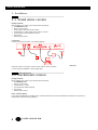
1. Introduction
This chapter is to familiarize the user with the operation of a modem. Note: <CR> indicates that the user must press the return
key after a command sequence.
1.1 The modem
A modem is a device that allows two terminals (DTE, PC...) to communicate via a telecommunication line (phone line).
The data is converted by the modem into electrical signals adapted to the telecommunication network. This conversion is called
modulation and demodulation.
Various conversion techniques have been developed to speed-up the data flow. The different speeds are particular to each
type of modulation: 300 bps in V21, 2400 bps in V22bis, 14400 bps in V32bis, 19200 bps in V32terbo and 33600 bps in V34.
1.2 The modem-fax
A fax device transmits scanned images via the telephone network.
In addition to traditional fax machines, the fax modem also allows transfer of computer data such as:
•= ASCII files from a text processor,
•= PCX or TIF files from a graphic editor, etc.
The Fax mode operation is controlled by a fax software which:
•= Converts files to T4 format (fax graphic format),
•= Transmits and receives faxes,
•= Supervises fax modem operation.
Supervision of the fax modem is carried out by a standard protocol: "Asynchronous Facsimile DCE Control Standard", Class 1
Service - TR 29.2188 or Class 2 Service - TR 29.2388.
The computer equipped with a fax modem will be able to transmit and receive fax in Group III mode:
•= At about one A4 page per minute,
•= In fine or standard resolution.
See chapter 5 for the list of modem class 1 and 2 commands.
1.3 Calling modes dialing
The modem can be in 2 modes:
Send or calling,
Receive or answer.
1.3.1 Calling Mode
The modem switches to originate mode when the dial command: ATD 37487126 is sent (example number).
The calling modem then waits for the remote modem to respond.
1.3.2 Answering Mode
The modem switches to answer mode when it detects ringing on the phone line.
The answer is carried out automatically if the command ATS0 = 2 was sent to the modem by the local PC. A training sequence
is then initiated. A training sequence is the hand-shake sequence between modems to establish a communication link. It
establishes speed, modes...
1.4 Leased line
A leased line is a permanent communication link dedicated between two modems. This kind of link is used for:
•= High usage,
•= Secure communications,
•= Privately managed networks.
The leased line, can be a:
•= 4-Wire type where there is:
1 transmit pair,
1 receive pair.
•= 2-Wire type where:
6
SALES: 0118 965 5100
Data-Link Modem
the same pair of wires is used for transmit & receive.
For a leased line, a modem is designated:
•= Originating modem (ORIGINATE or MASTER),
•= The other as the answering modem (ANSWER or SLAVE).
Modems in leased line mode always try to connect when power is on, in order to provide permanent a link.
The MDU903/4 modem can establish leased line connections in the following speeds:
V22
1200 bps
V22bis
2400 bps
V32
9600 bps/4800 bps
V32bis
14400 bps/12000 bps
V32terbo
19200 bps/16800 bps
V34
33600 bps down to 2400 per steps of 2400 bps
In case of failure on the leased line, the MDU903/4 modem performs automatic switch-over to the dial-up PSTN. It then
monitors the leased line until it finds a connection has been re-established.
1.5 Protocols
Two types of protocols can be used to improve communication performance between two modems:
•= Error correction:
MNP4 or V42 detect errors which occurred during data transmission, and either correct them or re-transmit the
data.
•=
Data compression:
MNP5 or V42bis compress the data and thus transmit at a higher effective speed.
These two types of protocols improve efficiency and reliability of a connection.
1.5 Memory
Beyond these basic principles, the modem offers other functions, aimed at improving performance and ease of use.
These functions are controlled via the memory (S-Registers) of the modem, and are available via the extended AT command
set.
These functions are described in chapter 4 of this manual.
Some of the extra functions are:
•= Storage of phone numbers,
•= Forced V24 signals,
•= Exchange of a password between two modems ("Answer Back"),
•= Pre-qualification of the telephone line,
TECHNICAL: 0118 931 2233
7
Data-Link Modem
2. Installation
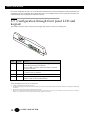
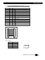
2.1 Stand alone version
Package Contents:
Before installing your modem, check all these items are present:
•= One MDU903/4 modem
•= One RJ11 phone cable
•= Power supply or 48V cable for SPC version
•= Leased line RJ-11 cable, except for STV and FTV versions
•= AT and V25bis command reference manual
•= User manual
•= Software (as an option)
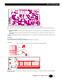
Connections:
Connect your modem as shown on the following diagram:
230 Vac
LL
(*)
Power On:
When the modem is connected, switch the power switch to the "On" position.
(*) Power supply DC adaptator or Power supply cable.
2.2 Rackmount version
Package Contents:
Before installing your modem, check all these items are present:
•= One MDU903C Card
•= One RJ11 phone cable
•= A leased line RJ-11 cable
•= AT command set reference manual
•= User manual
•= Software (as an option)
Rack - Controller Option:
If your rack is equipped with a controller card for modem supervision, the control card interface is located at the U10 position of
the MDU903C Card (see following diagram).
8
SALES: 0118 965 5100
Data-Link Modem
+
-
+
+
+
+
+
+
+
11
~
~
+
-
+
If the U10 position is empty, your MDU903C Card will not be recognized by the rack controller.
If you ordered the busy out function, check that the K3 option is available. This function forces the line to be active when there
is:
•= A faulty power supply,
•= No answer to a call after N rings (N is set by the S20 register). This maybe due to a non-connected data terminal (DTR/108
absent).
•= N successive ineffective connection sequences (N is set by the S20 register). This maybe due to a bad connection to the
telephone line.
This option is particularly useful for line pooling applications, and in case of fault, incoming calls are switched to another modem
in the pool.
Installation:
See rack operation manual to install your modem.
Find an empty location in the rack and insert the MDU903C Card into its card guide.
Connection:
Connect your modem from the rear of the rack, according to the following diagram:
LL
Power On:
Inserting the modem card connects it to the power supply of the rack. Power-on is carried out by the power switch located at
the rear of the rack.
TECHNICAL: 0118 931 2233
9
Data-Link Modem
2.3 Power-up self-test
When the modem is turned on, an automatic self-test is performed, which tests:
•= Its program memory
•= Its data memory
•= Its stored memory
•= Its data processing unit
The test lasts a few seconds and ends with a series of:
•= Different tones if the test is ok,
•= The same tone if a failure is detected. This failure is stored in the S19 register or detailed by the ATi7 command. See
chapter 6 "Troubleshooting".
The self test result is displayed on the front panel LCD of the modem.
2.4 Operating modes
This chapter describes the operation of the Data-Link modem.
The modem can operate in one of the four following modes:
1. IDLE MODE:
•= The modem enters the idle mode after powering up if it passes its power-up self test. Beeps announcing the end of the test
can be heard unless the speaker is turned off (see corresponding command).
•= From this mode, the modem will enter in command mode by receiving a command from the DTE, or in ONLINE mode if an
automatic call is initiated from the front panel, or if a call is received when the modem is configured to answer calls.
2. COMMAND MODE:
•= The modem enters the command mode when it receives a recognized command. In this mode, commands are interpreted
and executed. (Configuration set up - automatic call request...). The modem also enters in command mode when it
recognizes an escape sequence in the data when in an on-line rude.
3. ONLINE MODE:
•= The on-line mode starts, when detecting a carrier signal from a remote modem.
4. TEST:
•= The test mode is selected when in a command mode using appropriate test commands.
The Front Panel
The front panel of the modem has six red LEDs and one push button.
The different LEDs indicate the state of the modem and the status of the self test sequence.
DTR
DSR/RI
CD
TXD
RXD
108
125/107
109
103
104
10
LINE
MODE
SALES: 0118 965 5100
Data-Link Modem
The following table list these functions:
LED
DTR (Data
Circuit
108
DSR/RI (Data
Set Ready/Ring
Indicator)
107/125
CD (Carrier
Detect)
109
TXD (Transmit
103
Function
Indicates that the data terminal equipment connected to the
modem is ready for data communication (also bad Ram
during power up test).
Flashes when an incoming ring is received (125/RI). Remains
lighted permanently when connecting. Also bad RAM causes
flashing of light during power up test.
Indicates that the remote modem's carrier signal has been
received by the modem. In test mode, this light will flash if the
test is negative. Also flashes if bad ram during power up test.
Flashes as data is transmitted by the modem.
104
Flashes as data is received by the modem.
-
Indicates the mode of connection:
Permanent: Leased Line
Flashing: PSTN
Off: Command Mode
Equally a sign of bad non volatile RAM during power up test.
PSTN
Off: 300 bps
Flash 1 Time = 1200 bps
Flash 2 Times = 2400 bps
Flash 3 Times = 4800 bps
Flash 4 Times = 7200 bps
Flash 5 Times = 9600 bps
Flash 6 Times = 12200 bps
Flash 7 Times = 14400 bps Flash 8 Times = 16800 bps
Flash 9 Times = 19200 bps Flash 10 Times = 21600 bps
Flash 11 Times = 2400 bps Flash 12 Times = 26400 bps
Flash 13 Times = 28800 bps
Flash 14 Times = 31200 bps
Lighted permanent = 33600 bps
Terminal
Ready)
Data)
RXD (Receive
Data)
LINE
The Push Button
The MODE push button programs different functions depending on the current mode.
IN COMMAND MODE:
•= Performs automatic dialing of the number stored in memory or holds the line in originate mode if no number was stored, or
starts answering if rings were detected on the line. The length of the press is signaled by a single flash of the DSR LED.
•= A two-second push holds the line in answer mode. The length of this push is signaled by two flashes of the DSR LED.
•= If the button is pressed for more than 10 seconds (three flashes of the DSR LED), the modem resets.
IN ON-LINE MODE:
•= Pressing the button once disconnects the modem and selects idle mode again.
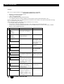
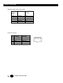
Configuration Select
Holding MODE for more than 10 seconds will initiate a hardware reset.
If the switch is still pressed after some beeps are heard, the modem will enter configuration mode.
The front panel LEDs DTR, DSR, CD and LINE indicate which configuration the user can select. There are listed in the
following table:
DTR
0
0
0
1
1
0
DSR
0
1
1
0
0
0
CD
1
0
1
0
1
1
LINE
1
1
1
1
1
0
0
1
0
0
0
1
1
0
1
1
0
0
0
1
0
0
Configuration
User configuration "0" (AT%M0)
User configuration "1" (AT%M1)
User configuration "2" (AT%M2)
User configuration "3" (AT%M3)
User configuration "4" (AT%M4)
Factory configuration "0" async dial configuration
(AT&F0)
Factory configuration "1" sync 2WLL configuration
originate (AT&F1)
Factory configuration "2" sync 2WLL configuration
answer (AT&F2)
Factory configuration "3" V25bis HDLC dialer (AT&F3)
Factory configuration "4" V25bis BSC dialer (AT&F4)
TECHNICAL: 0118 931 2233
11
Data-Link Modem
Each of the configuration will stay on for 2 seconds while the MODE button is pressed. Releasing the button will select the new
configuration, and this configuration will be loaded after power up. Immediately after the power up test (after the beeps), the
LEDs will indicate which configuration is loaded for 2 seconds.
2.5 Configuration through front panel LCD and
keypad
This chapter describes states of the front panel lights and operation of the LCD and keypad.
The four LEDs indicate the state of the modem
LED
Circuit
DSR/Ri 107/125
CD
109
DATA 103/104
DTR
108
Function
Flashes when an incoming ring is receiving (125-Ri).
Flashes during training on leased line.
ON when DSR is activated, when the modem is off hook
and when connected.
Indicates that the modem is connected to the remote one,
i.e. remote carrier is detected.
Flashes as data are received and transmitted by the modem.
Indicates that the data terminal equipment connected to the
modem is ready for data communication.
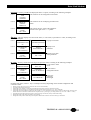
LCD displays
The LCD displays two lines of 16 characters:
It displays results of the self test after power on.
The main menu displays successively states of the modem (connection, speed, DTE interface statuses) and branches to configuration and dialing
sub-menues.
Theses menus are described on the next double page diagram.
Three keys are used to pass between menues: down ↓ key accesses next item in a list, enter ↵ key validates a choice or branches to a sub-menu,
and left ← key comes back one step to the main menu with no effect on last choice.
Three keys operation
12
SALES: 0118 965 5100
Data-Link Modem
↵ ENTER : This key validates the displayed choice or option, according to the following examples:
Case 1
PRESS ENTER Enter branches to the configuration sub-menus.
FOR
CONFIG
CHANGE
Case 2
CHANGE ?
VISUAL
DISPLAY
Enter branches to the AT display parameter submenus.
Case 3
COMMAND
ECHO
ON > OFF
Enter selects the new value of the parameter
located on the right of the « > » symbol.
↓ DOWN : This key displays next item of the menu, i.e. next menu, or parameter or value, according to the
following examples:
Displays next menu.
Case 1
↓
SELECT
STORE
CONFIGURATIO
CONFIGURATION
N?
?
Case 2
COMMAND
ECHO
ON CHANGE?
Case 3
COMMAND
ECHO
ON > ON
↓
QUIET
OFF CHANGE ?
↓ COMMAND ECHO
ON > OFF
Displays next
parameter.
Displays next value
of the parameter.
← LEFT : This key comes back one step to the previous menu, according to the following examples:
Case 1
Comes back to main
←
CHANGE ?
MDU903/4
menu.
MODEM OPTION
REV 5.01
Case 2
COMMAND
ECHO
ON CHANGE ?
Case 3
COMMAND
ECHO
ON > OFF
←
CHANGE ?
VISUAL DISPLAY
← COMMAND ECHO
ON CHANGE ?
Comes back to
configuration menu.
Leaves the
parameter
unchanged.
From the main menu, LEFT ← key is a multiple action key depending on the modem configuration and
connection status:
•=
•=
•=
•=
•=
•=
•=
•=
During training, left key aborts the connection and restores command mode,
In on line mode, left key disconnects,
In idle mode, if the modem is configured in leased line mode, left key initiates a leased line training,
In idle mode when incoming rings are detected, left key initiates answer mode (acts as an ‘ATA’ command),
In idle mode when the modem is configured in dial up mode (i.e. not in leased line mode), left key initiates a calling mode connection. The
modem dials the first automatic number found in the phone book, or just hangs up in calling mode if any (acts as an ‘ATDS’ or ‘ATD’),
In leased line mode with dial backup option set, during training on lease line, left key initiates dial backup,
During dial backup with alarm beep, left key stops beeping,
During dial backup without alarm beep, left keep aborts the dial line connection and starts training on leased line.
TECHNICAL: 0118 931 2233
13
Data-Link Modem
Example
How to store a phone number in the phone book as would this AT command:
AT&Z3:BLACKBOX:FOX:33237:::A
•=
•=
•=
•=
•=
Number 3 in the phone book (range 0 to 99),
« BLACKBOX » is the name field,
« FOX » is the password field,
LINK and CONGURATION fields are both left blank,
« A », attributes means this number is dialed from the front panel or from the DTE interface (DTR, 108-1).
NOTA : Please refer to the AT command reference manual for more details on the phone book fields and usage
(see AT commands: &N, &Z, DS).
While editing the number, the modem keeps modification in its memory:
•=
•=
•=
You may stop editing, and restart later,
This memory is not saved: modification will be lost in case of reset by ATZ command or power lost,
To save memory and make modification permanent, you must validate the last menu of the number editing: « PRESS
ENTER TO SAVE NUMBER MEMORY ».
#
1
On display
PRESS ENTER
FOR
CONFIG
CHANGE
Press the key
↵ to access configuration
menus, then ↓ to display :
2
CHANGE?
PHONE
NUMBERS
↵ to access phone number
editing sub-menus
3
CHANGE? P00:O
123456
↓ to access number 3
4
CHANGE? PO3 :
↵ to start editing number 3
5
P03:--NAME--?
↵ to edit the NAME field
↓ would access to
the PASSWORD
next field
6
PO3:--NAME-_
Note that the ?
symbol is gone. Note
the cursor position
7
PO3:--NAME-C
8
PO3:--NAME-_
9
PO3:--PASSWORD--?
↓ three times to displays
« C » character. Then leave ↓
pressed until you get a « C »
again
↵ to validate this first
character, the cursor moves
on the right. Press ↓ to get the
« X », then ↵, then ↓ to get
the « R », then ↵
↵ no character is displayed on
the cursor: ENTER key
validates this field and initiate
next field editing
Just like steps 5 to 8, press :
↵ once to start editing,
↓ to get « F », then ↵ (« F- »)
↓ to get « O », then ↵ (« FO- »)
↓ to get « X », then ↵ (« FOX- »)
↵ to validate « FOX », as the
14
SALES: 0118 965 5100
Comments
00 already exists in
this example. Look
at the name on line 1
an the number on the
second line,
03 is empty in this
example
↵ validate a field on
a blank cursor
Data-Link Modem
#
On display
10
PO3:--NUMBER-?
11
PO3:--LINK--?
NONE
12
PO3:--CONFIG--?
NONE
↓ to get next field
13
PO3:-ATTRIBUTE-NONE
↵ to edit attribute field
14
PO3: NONE
AUTO CALL >
ON ?
↵ to validate this choice
15
↓ to display next attribute
PO3: A
DIAL OUT > ON ?
16
PO3
A
PASSWD ACCS>ON ?
17
SAVE MEMORY
Press the key
password and access to the
next field of this number
Again like previous steps,
press:
↵ once to start editing,
↓ to get « 3 », then ↵ (« 3- »)
↓ to get « 3 », then ↵ (« 33- »)
↓ to get « 2 », then ↵ (« 332- »)
↓ to get « 3 », then ↵ (« 3323- »)
↓ to get « 7 », then ↵ (« 33237- »)
↵ to validate « 33237 »,
↓ to get next field
Comments
Note that dialable
digits are available
as well as control
character. Refer to
the dial command
ATD in the reference
manual
Note the attribute on
the first line
↓ 4 times to pass other
attributes and display next
menu
↵ to save these changes in
permanent memory, or
← to ignore and return to
configuration menu (step 2)
without saving memory
2.6 Dialogue
For your first dialogue with your modem, install communication software on your micro-computer.
Your MDU903/4 modem will recognize automatically the communication speed and format of your computer, up to 115200 bps,
as soon as you enter the following characters:
AT <CR> (Carriage return)
Answer: OK
AT&S <CR>
Answer: Displays configuration pages.
* Identification model.
Once this first dialogue is established, the reference manual will help you to perform complete operation of your modem.
TECHNICAL: 0118 931 2233
15
Data-Link Modem
3. Configurations
This chapter describes commonly used configurations through the AT command set: These commands may be used as part of
software drivers for example. The same configuration can be achieved through the LCD and keypad front panel. Refer to the
LCD menu diagram provided in chapter 2.5.
3.1 Factory configuration
This configuration applies when the modem is first powered on, or after complete reset by the following commands:
AT&W255 <CR>
Answer : OK
ATZ <CR>
Answer : OK
This configuration is designed for most common applications and has the following characteristics:
DTE - V24:
Normal CD, DTR,
DSR activated on handshake,
CTS controlled by DTR in command mode and RTS in on line mode.
Automatic answer S0 = 2
Automatic hunt: V34, V32bis, V32, V22bis, V21 and V23 modes
Error correction and data compression: V42bis and MNP automatic mode (S0?)
Flow control: RTS/CTS
This configuration can be modified for a specific application. The following examples describe the most common applications.
3.2 Flow control
Flow control can either be performed physically using the RTS/CTS signals or via software using the Xon/Xoff protocol. The
following table shows how to activate each form of flow control.
Xon - Xoff:
AT*LG1 <CR>
AT*LR1 <CR>
or AT&K4 <CR>
Or RTS - CTS:
AT%C1 <CR>
AT&R1 <CR>
AT*LG2 <CR>
AT*LR2 <CR>
or AT&K3 <CR>
3.3 Synchronous mode
Synchronous mode is when the DTE provides a clock to which the data being transmitted or received must be synchronized. It
provides a more efficient means of data transmissions as longer pockets of data can be strung together.
The following table shows how to enable this feature.
AT*M0 <CR>
AT&M1 <CR>
AT&X1 <CR>
AT@V0 <CR>
If the synchronization clock is provided by the DTE, send the command: AT&X1 <CR>
If the DTE transmits a continuous flow of data it is recommended to disable the COMMAND mode of the modem, to prevent
escape characters from appearing in the course of data transmission or constant polling. To do this, send the command:
AT@V0 <CR>
16
SALES: 0118 965 5100
Data-Link Modem
3.4 Automatic dialing directory
The MDU903/4 has a non volatile memory that allows the user to store frequently used numbers. Each phone number can
have a name and control sequence associated. So instead of remembering every number, the user can type in the recipient
name, thus greatly easing the task of making a connection.
The following example shows how to store a number, name and control sequence at location 3 of the directory memory.
Dialing a direct line, send the command:
ATDT36062424 <CR>
Dialing via a PABX, send the command:
ATDP0W36062424 <CR>
Storing a number in the directory (number 3), send the command:
AT&Z3:NAME:CONTROL:P0W36062424:::A <CR>
Show directory contents, send the command:
AT&N <CR>
Dialing from the directory:
•= The ATDSn command dials the stored telephone number specified by n where n is 0 to 99.
•= By CCITT 108/1 operation. The modem autodials a stored number when an off-to-on transition of the DTR occurs. The
modem disconnects when an on to off transition of the DTR occurs. AT&D1 command select the dialing mode of the DTR
signal.
3.5 Leased line
As mentioned before, a leased line is a permanent analogue telephone connection between 2 sites. Therefore there is no
dialing necessary.
Depending on the selected configuration, the following commands are sent to the modem.
(See reference manual for a description of these commands).
Configuration
2-wire line
4-wire line
Dial back up
1234 back up dial number
Recovery lookback
Originating modem
AT&L1%O1&W <CR>
AT&L2%O1&W <CR>
AT%U1
AT&Z:::1234:::A <CR>
AT%L1&W <CR>
Answering modem
AT&L1%O0&W <CR>
AT&L2%O0&W <CR>
AT%U1
AT%L1&W <CR>
after this leased line configuration is saved by the AT&W command, the modem will start training on leased line if :
•=
it is reset by ATZ or by a power restart,
•=
the front panl button is pressed.
3.6 Saving user configurations
The MDU903/4 modem can store up to 5 user configurations.
The AT&Wn command saves the current configuration in non-volatile memory (n = 0 to 4). This configuration is saved even
when the modem is turned off. The modem will load the last saved user configuration at power-up.
TECHNICAL: 0118 931 2233
17
Data-Link Modem
4. Security and memory
4.2 Principles
The modem contains three types of memory:
The PROM, where factory configuration is stored permanently,
The RAM, where the modem configurations are stored temporary,
The NVRAM where semi-permanent data is stored even when the modem is turned off.
The first time your modem is turned on, or after a complete reset, these three memories are identical and set to the default
factory configuration.
The AT&Wn command saves the current configuration in the non-volatile memory, (n = 0 to 4).
The last stored user configuration will be loaded automatically on next power-up.
These memory operations are shown on the following diagram:
PROM
NV-RAM
Factory
configuration
AT&W255
Stored
configuration
AT&W
AT&F
Active
configuration
AT%m or
Power-up
RAM
AT&W255
Memory reset
AT&W0 to AT&W4
Memory store
Loading of a factory configuration without loosing the stored AT&F0 to AT&F4
memory
AT%m0 to AT%m4
Loading the user configuration
4.2 The phone directory
Up to 100 phone numbers can be stored in the modem's non-volatile memory, to be used by the automatic dialer.
AT&Z0:Directory::11:::A
Save a number
This command saves automatically the directory in non-volatile memory
ATDS0 <CR>
Dial a number
AT&N <CR>
Display the directory
18
SALES: 0118 965 5100
Data-Link Modem
4.3 Answerback security
This security mode is controlled by the answering modem, and depends on a password exchange which authorizes a modem
connection, i.e.:
Calling
Answering
ATDxxx
ring
Training
ENQ ()
"AC24Y"
control process
"AC24Y"
(for example)
If the answerback matches the one stored in memory within two seconds after an ENQ code was sent by the answering
modem, access is granted.
Otherwise the modem disconnects automatically.
To store the answerback code, see the following example. The password can be up to 12 characters long.
Store answerback (for example: AC24Y)
To disable answerback security
AT&A:AC24Y:AC24Y <CR>
AT&A:: <CR>
4.4 Callback security
This security mode is controlled by the answering modem.
It sends a password and then calls back the telephone number associated with that passsword.
See %SA and %SB commands in the reference manual.
HERE
N 3132
THERE
N 4142
ATS0=2
AT%SB1
ATS0=2
AT%SA1
AT&Z3:HERE:CALLB1:3132:::CD
ATD4142
Calling
Training
Password?
« call B1 »
Disconnecting
Calling (3132)
Training
Password ?
« Call B1 »
Modems are connected
The double security guarantees password and localization of the calling modem.
TECHNICAL: 0118 931 2233
19
Data-Link Modem
4.5 Inactivity password
The modem asks for a password when no data passes through it for a presented delay. If this password matches the operator
or supervisor password stored in memory then the modem will reconnect otherwise it will drop the line.
S32: number of minutes of inactivity that will start the password request.
S96: number of seconds that the modem will wait for the password.
AT%ST 0/1: number of password trials (0: one trial / 1: three trials).
AT%In: inactivity is detected if:
n=0: no detection, i.e. feature is disabled.
n=1: detects transmitted data inactivity.
n=2: detects received data inactivity.
n=3: detects both received and transmitted data inactivities.
AT%PS: SUPER:SUPER: stores the supervisor password, (SUPER as an example).
AT%PO: OPE:OPE: stores the operator password (OPE as an example).
20
SALES: 0118 965 5100
Data-Link Modem
5. Specifications
5.1 Line side characteristics
Mode
Receiver sensitivity
Carrier detection:
Open threshold
Close threshold
Transmission level:
Nominal
Maximum
Minimum
Switched network
- 43 dBm
2-wire leased line
- 33 dBm
4-wire leased line
- 26 dBm
< - 48 dBm
> - 43 dBm
< - 38 dBm
> - 33 dBm
< - 31 dBm
> -26 dBm
- 10 dBm
- 8 dBm
- 16 dBm
- 14 dBm
- 6 dBm
- 16 dBm
- 14 dBm
- 6 dBm
- 16 dBm
RecomCall/Answer
mendations
V22 bis
Call
Answer
V22
Call
Answer
V21
Call
Answer
V23
Call
Answer
V32
V32 bis
V32 terbo
V34
Speed Bps
Xmit 0
Xmit 1
2400
2400
1200
1200
300
300
75
1200
9600
14400
19200
33600
1200
2400
1200
2400
1180
1850
450
2100
1800 Hz
1800 Hz
1800 Hz
Adaptive
1200
2400
1200
2400
980
1650
390
1300
Received
0
2400
1200
2400
1200
1850
1180
2100
450
Received
1
2400
1200
2400
1200
1650
980
1300
390
5.2 Automatic call & answer
Originating
Automatic dialing or calling by the originating modem is initiated by:
•= "AT" or V25bis commands
•= Push button on front panel
•= DTR 108/1 being enabled
•= Pulse or tone dialing.
Tone recognition occurs when there is:
•= A dial request (public network or private exchange).
•= A busy line.
Answering a Call
When the modem is set in answer mode, it will go off hook after 2 rings (if the command ATS0=2 is sent). This is in conformity
with CCITT V25bis recommendation.
Connection - Disconnection
In calling mode, the modem will automatically recognize the remote modem modulation type and adapt correspondingly.
It will disconnect only if:
•= The carrier is lost,
•= No carrier tone is detected within 35 to 90 seconds,
•= No data activity has occurred for the selected period of time dictated by the Inactivity Timer.
TECHNICAL: 0118 931 2233
21
Data-Link Modem
5.3 Serial interface
The V24 serial interface of the modem conforms to the DCE specifications. A straight ribbon cable is all that is needed to
connect to the DTE port of your computer or terminal. The serial port will automatically recognize DTE speeds up to 115200
bps. This is called auto-bauding.
Both asynchronous and synchronous modes with internal or external clock are supported.
5.4 Fax-mode
Automatic Call and Answer
See 5-2
Transmission Modes
The modem provides the ability to send and receive faxes at speeds up to 9600 bps.
The following modulations are supported:
ITU-T
V21
V27 ter
V29
Speed Bps
300
2400 / 4800
7200 / 9600
Carrier (Hz)
1650 - 1850
1800
1700
Operating Mode
In fax mode, the modem support the following standards:
•= Group III Fax, EIA 578 class 1 and class 2 compatible,
•= CCITT T4 - T30 recommendations.
Service Class 1 Command Set
The following AT commands control the operation of a class 1 modem/fax:
+FCLASS
Service class identification and control
+FTS
Stop transmission and wait
+FRS
Receive silence
+FTM
Transmit mode
+FRM
Receive mode
+FTH
Transmit T30 command mode
+FRH
Receive T30 command mode
+FCERROR Error code
Service Class 2 Command Set
The following AT commands control the operation of a class 2 modem/fax:
+FCLASS
Service class identification and control
+FMDL
Fax-modem model
+FMFR
Fax-modem manufacturer
+FREV
Fax-modem checkup
+FBUG
Frame report
+FAA
Automatic answer
+FBOR
Data bit order
+FDCC
Fax-modem capability selection
+FDIS
Capability initialization for transmission
+FLID
Identification selection of the fax-modem
+FCON
Remote fax detection
+FCIG
Identification of called subscriber by CIG
+FCSI
Identification of called subscriber by CSI
+FTSI
Identification of calling subscriber by TSI
+FDTC
Called fax return capability - DCS frame
+FDCS
Discussed capability for process - DCS frame
+FHR
Content of received frame
+FHT
Content of transmitted frame
+FBUF?
Buffer state
+FDT
Fax message transmission
22
SALES: 0118 965 5100
Data-Link Modem
+FPTS
+FDR
+FCFR
+FPTS
+FET
+FHNG
+FAXERR
Page transmission result
Fax message reception
Reception mode confirmation
Remote reception status
End of page status
End of procedure status
Error code
5.5 General characteristics
Dimensions :
Length: 260 mm,
Width: 170 mm,
Height: 35 mm.
Weight: 0,7kg.
External power supply module: 230V/50Hz.
Power consumption: 25mA.
Operating temperature: 0 to 50°C.
Relative humidity: 0 -> 90% non-condensing.
Conforms to European security standards: EN41003, EN60950,
Conforms to European Electromagnetic Standards: EN50082, EN55022.
TECHNICAL: 0118 931 2233
23
Data-Link Modem
6. Troubleshooting
Problem:
This chapter lists most modem operating problems.
Problem
No tone when
modem is turned
on
Single and
continuous tone
when modem is
turned on
Check
Connection to the mains On/Off switch in On position Power supply
of the rack and fuse of the card (rack version), DTR indicator on or
flashing
Send commands:
AT&W255 <CR>
ATZ <CR>
Then restart the modem to see if the same continuous tone is heard.
See S19 section below.
Flashing of the TXD indicator when sending characters. No flash:
check V24 cable. Flashes: <CR> command:
AT&S4 <CR>
and check for a long flash of TXD indicator. Long flash: check V24
cable.
Try to dial an outside line using the ADT command. Make sure that
you select a valid telephone number and dialing mode (P-Pulse, TTone). Listen to the internal speaker to see if the normal dial tone is
heard. If not then it is a problem with the line connection.
Check for any blacklisting:
AT&NB <CR>
(see reference manual) Turning the modem off and on resets the
blacklist.
Modem does not
obey commands
Modem answers
"NO DIAL TONE"
Modem refuses to
dial
ATI7 command:
Check the answer to the ATI7 command. It provides a clear message in case of self detected problem.
ATI7 Response
BAD ROM
BAD RAM
BAD NOW VOLATILE
MEMORY
BAD DSP ROM
BAD DSP
ALB FAILED
Code EPROM checksum bad
Write and read failure in RAM
No volatile memory checksum bad
DSP checksum bad
DSP bad
Analog loopback test bad
If a problem persists after these verifications, contact the BLACK BOX "Hot Line" service:
HOTLINE: +44 118 931 2233
.
24
SALES: 0118 965 5100
Data-Link Modem
7. Appendix A – V24 Signals
Pin number
1
2
3
4
5
6
7
8
9-19
10-16
15
Name
TXD
RXD
RTS
CTS
DSR
GND
CD
SS
Si
SCT
17
18
20
21
22
24
SCR
TB3
DTR
DB2
RI
SX
25
TEST
CCITT number
101
Earth protection
103
Data transmission
104
Data reception
105
Request to send
106
Clear to send
107
Data terminal ready
102
Signaling earth
109
Carrier detect
116
Dial backup command
117
Dial backup indicator
114
Time basis for signal elements at transmission.
Source: ETCD
115
Time basis for signal elements at reception
141
Test command. Local loop 3.
108/2
Data terminal ready
140
Test command: remote control of loop 2
125
Ring indicator
113
Time basis for signal elements transmission. Source:
ETTD.
142
Test indicator.
TXD
CABLE DB9 - DB25
PC - MODEM
3
2
TXD
RXD
2
3
RXD
RTS
7
4
RTS
CTS
8
5
CTS
DSR
6
6
DSR
GND
5
7
GND
DCD
1
8
DCD
DTR
4
20 DTR
RI
9
22 RI
Dial line connector:
Pin
1
2
3
4
5
6
Signal
Not used
Telset Tip
Tip PSTN
Ring PSTN
Telset Ring
Not used
1 2 3 4 5 6
TECHNICAL: 0118 931 2233
25
Data-Link Modem
CBL903-UK (Dialup cable for use in the UK)
Pin
(Modem)
RJ-11
6 wire
1
2
3
4
5
6
Signal
Pin (Line)
BT631A
Not used
Telset Tip
Tip PSTN
Ring PSTN
Telset Ring
Not used
N/C
N/C
2
5
N/C
N/C
Leased line connector :
Pin
1
2
3
4
5
6
26
Signal 2W
Not used
Not used
Tip
Ring
Not used
Not used
Signal 4W
Not used
Receive Tip
XMIT Tip
XMIT Tip
Receive ring
Not used
SALES: 0118 965 5100
1 2 3 4 5 6
Data-Link Modem
8. Appendix B - Country specific informations
UK
Although this equipment can use either loop disconnect or DTMF signalling, only
the performance of the DTMF signalling is subject to regulatory requirements for
correct operation. It is therefore strongly recommended that the equipment is set
to use DTMF signalling for access to public or private emergency services. DTMF
signalling also provides faster call set up.
TECHNICAL: 0118 931 2233
27
Data-Link Modem
28
SALES: 0118 965 5100