1
Model 7300
Service Manual
Aug 27, 1999
Part Number 9226-90-00
Novametrix Medical Systems Inc.
P.O. Box 690
5 Technology Drive
Wallingford, Connecticut, U.S.A. 06492.
Service Policy
Novametrix Medical Systems Inc. provides 24-hour a day access to technical support
through its Technical Support Department in Wallingford, Connecticut, and company
Service Representatives located throughout the United States. (Outside the U.S.,
primary technical support is handled through our qualified international sales and
service distributors.)
Novametrix will provide Warranty Service support within 48 hours of receiving a request
for assistance. Contact the Technical Support Department by telephone toll free at 800243-3444, or 203-265-7701; by facsimile at 203-284-0753; or, by e-mail at
[email protected]. After hours telephone support requests (before 8:00 AM
and after 5:00 PM Eastern Time) will be responded to promptly by the Technical
Support on-call staff. After hours facsimile and e-mail requests will be answered the
next business day. It is suggested that any person calling in for technical support have
the equipment available for product identification and preliminary troubleshooting.
Novametrix reserves the right to repair or replace any product found to be defective
during the warranty period. Repair may be provided in the form of replacement
exchange parts or accessories, on-site technical repair assistance or complete system
exchanges. Repairs provided due to product abuse or misuse will be considered “nonwarranty” and invoiced at the prevailing service rate. Replaced or exchanged materials
are expected to be returned to Novametrix within 10 days in order to avoid (additional)
charges. Return materials should be cleaned as necessary and sent directly to
Novametrix using the return paperwork and shipping label(s) provided (Transferring
return materials to a local sales or dealer representatives does not absolve you of your
return responsibility.).
Novametrix manufactures equipment that is generally field serviceable. When repair
parts are provided, the recipient can call Technical Support for parts replacement
assistance and repair assurance. In the event a replacement part requires increased
technical capability, Technical Support may request Biomedical assistance, provide onsite technical support or complete replacement equipment. If the customer requires the
return of their original product, the exchange material will be considered “loaner
material” and exchanged again after the customer equipment is repaired.
Novametrix promotes customer participation in warranty repairs, should they become
necessary. A longer useful product life, and quicker, more cost-effective maintenance
and repair cycles—both during and after the warranty period, are benefits of a smooth
transition into self-maintenance. The Technical Support Department can provide
technical product support at a level appropriate to your protocol and budget
requirements.
Please contact Technical Support for information on these additional programs and
services:
• Focus Series Technical Training Seminars
• Test Equipment and Test Kits
• Service Contract / Parts Insurance Plans
• On-Site Technical Support
• “Demand Services” including:
Flat rate parts exchange
Flat rate return for repair
Time and material,
Full warranty, discounted replacement sensors.
Rev. 00
Model 7300 Service Manual
iii
Warranty
Equipment manufactured or distributed by Novametrix Medical Systems Inc., is fully
guaranteed, covering materials and workmanship, for a period of one year from the
date of shipment, except for certain disposable products and products with stated
guarantees other than one year. Novametrix reserves the right to perform guarantee
service(s) at its factory, at an authorized repair station, or at the customer’s installation.
Novametrix’ obligations under this guarantee are limited to repairs, or at Novametrix’
option, replacement of any defective parts of our equipment, except fuses, batteries,
and calibration gasses, without charge, if said defects occur during normal service.
Claims for damages during shipment must be filed promptly with the transportation
company. All correspondence concerning the equipment must specify both the model
name and number, and the serial number as it appears on the equipment.
Improper use, mishandling, tampering with, or operation of the equipment without
following specific operating instructions will void this guarantee and release Novametrix
from any further guarantee obligations.
Service Department
For factory repair service:
Call toll free: 1-800-243-3444
To Call Direct: (203) 265-7701
Facsimile (203) 284-0753
http://www.novametrix.com
[email protected]
Caution: Federal (U.S.A.) law restricts this device to sale, distribution, or use by or on
the order of a licensed medical practitioner.
Copyright ©1999. Novametrix Medical Systems Inc.,
5 Technology Drive, Wallingford, Connecticut, 06492.
All rights reserved.
iv
Model 7300 Service Manual
Rev. 00
Table of Contents
Safety .............................................................................................................................................................. 1
Warnings .................................................................................................................................................. 1
Cautions ................................................................................................................................................... 2
Notes ........................................................................................................................................................ 2
Introduction .................................................................................................................................................... 5
About this manual ..................................................................................................................................... 5
Front and Rear Illustrations ...................................................................................................................... 5
NICO Monitor Technical Description ........................................................................................................ 6
Manufacturing Quality & Safety ................................................................................................................ 6
Declaration of Conformity with European Union Directive ........................................................................ 6
Trademarks and Patents .......................................................................................................................... 6
Manual Revision History ........................................................................................................................... 6
Theory of Operation ...................................................................................................................................... 7
NICO Model 7300 Non-Invasive Cardiac Output Monitor ......................................................................... 7
Digital Board 2763 .................................................................................................................................... 7
Microprocessor .................................................................................................................................. 7
Background Mode Debugging and Application Development ......................................................... 11
System Memory .............................................................................................................................. 11
User Interface Control Circuitry ....................................................................................................... 12
Real Time Clock, Power on RESET Generation and Glue Logic .................................................... 12
Power Supply 2764 (Power Supply and Communications) .................................................................... 13
Serial Communications UART ......................................................................................................... 13
CO2 Pulser Source Drive ................................................................................................................ 15
CAPNOSTAT Case and Detector Heater Control ........................................................................... 16
Saturation LED Power Generation and LED Drive .......................................................................... 17
Power Supply and Voltage Reference Generation .......................................................................... 17
Logic and Input / Output Signal Control .......................................................................................... 20
Analog Board 2765-01 ............................................................................................................................ 20
CAPNOSTAT Interface ................................................................................................................... 20
CO2 Input Signal Path ..................................................................................................................... 20
CO2 Case and Detector Heater Regulation .................................................................................... 21
Flow Zeroing and Patient Line Purging ........................................................................................... 22
Flow Circuitry ................................................................................................................................... 22
Barometric and Airway Pressure ..................................................................................................... 23
Patient Airway Adapter Type Sensing ............................................................................................. 23
NICO Sensor Rebreathing Valve Control ........................................................................................ 24
Saturation Input Signal Path and Signal Conversion ...................................................................... 24
Functional Testing ....................................................................................................................................... 25
Equipment Required ............................................................................................................................... 25
Functional Test ....................................................................................................................................... 25
Accuracy Tests ............................................................................................................................................ 29
Equipment Required ............................................................................................................................... 29
CO2 Testing ............................................................................................................................................ 29
SpO2 Testing .......................................................................................................................................... 30
Flow Testing ........................................................................................................................................... 31
Time / Date Setting ................................................................................................................................. 31
Electronic Tests ........................................................................................................................................... 33
Rev. 00
Model 7300 Service Manual
v
Equipment Required ............................................................................................................................... 33
Power Supply ......................................................................................................................................... 34
Voltage Checks ...................................................................................................................................... 35
CO2 Testing ............................................................................................................................................ 37
SpO2 Testing .......................................................................................................................................... 37
Flow, Barometric Pressure and Rebreathe Valve Testing ...................................................................... 38
Serial / Analog Testing ........................................................................................................................... 40
Safety Testing ........................................................................................................................................ 40
Maintenance ................................................................................................................................................. 41
General .................................................................................................................................................. 41
Maintenance Schedules ......................................................................................................................... 41
Cleaning and Sterilization ....................................................................................................................... 41
Monitor ............................................................................................................................................ 41
SpO2 Finger Sensor ........................................................................................................................ 41
SpO2 Y-Sensor .............................................................................................................................. 42
SpO2 Y-Strip Tapes and Foam Wraps ........................................................................................... 42
Ear Clip ........................................................................................................................................... 42
NICO Sensors ................................................................................................................................. 42
CAPNOSTAT CO2 Sensor .............................................................................................................. 42
Disassembly ........................................................................................................................................... 43
Equipment Required ....................................................................................................................... 43
Disassembling Unit ......................................................................................................................... 43
Reassembling Unit ................................................................................................................................. 44
Battery Maintenance .............................................................................................................................. 44
Replacing the Internal Battery ................................................................................................................ 44
Mains Voltage Configuration .................................................................................................................. 45
Fuse Replacement .......................................................................................................................... 46
Software Update Instructions ................................................................................................................. 47
Equipment Required ....................................................................................................................... 47
Setup ............................................................................................................................................... 47
Procedure ........................................................................................................................................ 48
Specifications .............................................................................................................................................. 51
General ................................................................................................................................................... 51
NICO ...................................................................................................................................................... 51
CO2 ................................................................................................................................................................................................ 51
Flow Sensor ........................................................................................................................................... 52
SpO2 .............................................................................................................................................................................................. 52
Monitor Specifications ............................................................................................................................ 52
NICO Accessories ....................................................................................................................................... 53
Parts Lists .................................................................................................................................................... 55
9226-00 Non-Invasive Cardiac Output Monitor, Model 7300 ................................................................. 55
9226-01 Main Assy ................................................................................................................................. 55
2763-01 Digital Board Assy .................................................................................................................... 56
2764-01 Power Board Assy .................................................................................................................... 58
2765-01 Analog Board Assy ................................................................................................................... 62
2766-01 CO2 Input Board Assy .............................................................................................................. 65
9392-01 Pump W Rsvr Assy .................................................................................................................. 65
Drawings ...................................................................................................................................................... 67
vi
Model 7300 Service Manual
Rev. 00
1
Safety
For maximum patient and operator safety, observe the following warnings, cautions
and notes.
1.1
Warnings
WARNING:
!
Indicates a potentially harmful condition that can lead to personal injury.
• Explosion Hazard: Do not use the NICO monitor in the presence of flammable
anesthetics. Use of this instrument in such an environment may present an
explosion hazard.
• Electrical Shock Hazard: Always turn the NICO monitor off before cleaning it. Do
not use with a damaged external power source. Refer servicing to qualified
service personnel.
• Connect the AC Mains power cord to a properly grounded hospital-grade outlet.
The NICO monitor should be connected to the same electrical circuit as other
equipment in use on the patient. Outlets of the same circuit can be identified by
members of the hospital’s engineering department.
• Failure of Operation: If the monitor fails to respond as described, do not use it
until the situation has been corrected by qualified personnel.
• Reuse (disassembly, cleaning, disinfecting, resterilizing, etc.) of the NICO
sensor may compromise the device functionality and system performance and
cause a potential patient hazard. Performance is not guaranteed if the NCIO
sensor is reused.
• Inspect the CO2, SpO2 and NICO sensors prior to use. Do not use if they appear
to be damaged or broken.
• Do not attempt to rotate the NICO sensor in the breathing circuit by grasping the
pneumatic tubes exiting the flow sensor.
• Do not apply excessive tension to any cable or the NICO sensor pneumatic
tubing.
• Periodically inspect NICO sensor tubing lines for kinks.
• Replace the NICO sensor if excessive moisture or secretions are observed in the
tubing.
• Do not use the NICO monitor if it is unable to properly identify the NICO sensor.
If the condition persists, refer the monitor to qualified service personnel.
• The NICO sensor connector should be properly inserted into the front panel
receptacle prior to connecting the NICO sensor to the breathing circuit, in order
to avoid a circuit leak, or occlusion of the NICO sensor tubing.
Rev 00
Model 7300 Service Manual
1
1
Safety
Cautions
• In the event the message NICO SENSOR FAILURE is displayed, remove the NICO
Sensor from the patient circuit.
• Patient Safety: Care should be exercised to assure continued peripheral
perfusion distal to the SpO2 sensor site after application.
• Inspect the SpO2 sensor site for adequate circulation at least once every four
hours.
• When applying sensors take note of patient’s physiological condition. For
example, burn patients may exhibit more sensitivity to heat and pressure and
therefore additional consideration such as more frequent site checks may be
appropriate.
• Do not position sensor cables or tubing in any manner that may cause
entanglement or strangulation.
• The NICO monitor is not intended to be used as a primary apnea monitor.
1.2
Cautions
CAUTION:
Indicates a condition that may lead to equipment damage or malfunction.
!
•
•
•
•
•
•
•
•
•
•
•
•
1.3
Use only Novametrix approved sensors and accessories with the NICO monitor.
Do not operate the NICO monitor when it is wet due to spills or condensation.
Do not operate the product if it appears to have been dropped or damaged.
Never sterilize or immerse the monitor in liquids.
Do not sterilize or immerse sensors except as directed in this manual.
No tension should be applied to any sensor cable or tubing.
To avoid the effects of excessive moisture in the NICO sensor, insert it in the
ventilator circuit with the pneumatic tubes upright. Excessive moisture in the
NICO sensor may affect the accuracy of the measurements.
Operate the monitor at temperatures between 10 to +40° C (50 to 104° F),
10-95% R.H. non-condensing.
Avoid storing the monitor at temperatures less than -10q C or greater than +55q
C (<14q F or >131q F) 10-95% R.H. non-condensing
Observe precautions for electrostatic discharge (ESD) and electromagnetic
interference (EMI) to and from other equipment.
Where electromagnetic devices (i.e., electrocautery) are used, patient
monitoring may be interrupted due to electromagnetic interference.
Electromagnetic fields up to 3 V/m will not adversely affect system performance.
Caution: Federal (U.S.A.) law restricts this device to sale, distribution, or use by
or on the order of a licensed medical practitioner.
Notes
NOTE:
A point of particular interest or emphasis intended to provide more efficient or convenient
operation.
• In order to ensure proper monitoring of oxygenation and ventilation:
• The use of pulse oximetry is recommended during NICO monitoring.
• Setting of ETCO2 and SpO2 alert limits is recommended.
2
Model 7300 Service Manual
Rev. 00
Notes
Safety
1
• A “NO RESPIRATION” alert is not generated when both the CAPNOSTAT CO2
sensor and the NICO sensor are disconnected from the NICO monitor.
• Be certain that the monitor is not in Demo Mode while monitoring. Demo Mode
can be identified by the flashing DEMO MODE label in the General Message
area of the display. To exit Demo Mode and return to normal monitoring mode,
turn the power off and back on.
• The NICO monitor contains no user serviceable parts. Refer servicing to
qualified service personnel.
• Do not attach an SpO2 sensor distal to a blood pressure cuff. Valid data cannot
be processed when the cuff is inflated. Attach the sensor to the limb opposite to
the site used for the blood pressure cuff.
• This product and its accessories which have patient contact are free of latex.
• The NICO monitor is Year 2000 compliant.
• Data Validity: Inaccurate SpO2 and Pulse Rate values may be caused by;
• Incorrect application or use of a sensor
• Significant levels of dysfunctional hemoglobin; carboxyhemoglobin or
methemoglobin
• Significant levels of indocyanine green, methylene blue, or other intravascular
dyes
• Exposure to excessive illumination such as surgical lamps—especially ones
with a xenon light source, or direct sunlight
• Excessive patient movement
• Venous pulsations
• Electrosurgical interference
• Use of an IABP.
• NICO measurements will occur provided the following conditions are met:
• The NICO sensor is properly installed in the patient’s breathing circuit.
• Valid flow and CO2 signals are detected with no significant signal artifact.
• VCO2 is greater than 20 mL/min.
• ETCO2 is between 15 and 70 mmHg (2.0 - 9.0 kPa or %)
• The tidal volume is greater than 200ml.
• The respiratory rate is between 3 and 60 br/min.
• The STOP/CONTINUE REBREATHING key is not illuminated.
• NICO is not paused by the monitor for any other reason (displayed in the C.O.
message area)
• When a new CAPNOSTAT CO2 sensor is attached to the monitor, or is moved
from one monitor to another, it must be adapter zeroed before use.
• After the life cycle of the equipment and accessories has been met, disposal
should be accomplished following national/local requirements.
• There is no screen indication during monitoring, except on start-up (or when the
SET ALERTS screen is displayed), as to when the NICO alert settings are off.
Rev. 00
Model 7300 Service Manual
3
1
Safety
Notes
[This page intentionally blank.]
4
Model 7300 Service Manual
Rev. 00
2
2.1
Introduction
About this manual
This document contains information which is proprietary and the property of
Novametrix Medical Systems Inc., and may not be reproduced, stored in a retrieval
system, translated, transcribed, or transmitted, in any form, or by any means, without
the prior explicit written permission of Novametrix Medical Systems Inc. Novametrix
reserves the right to change specifications without notice.
2.2
Front and Rear Illustrations
Front panel keys
Knob
Operate/standby key
Display screen
NICO sensor input connection
SpO2 sensor input connection
CAPNOSTAT CO2 sensor input connection
Serial number label
Power cord entry module
(power cord receptacle
and fuse housing)
Rear panel power switch
Power cord retainer
(secure power cord)
Equipotential connection
(connection to monitor chassis)
Rev 00
Rear panel
power connectors
Model 7300 Service Manual
5
2
Introduction
2.3
NICO Monitor Technical Description
NICO Monitor Technical Description
Per requirements of IEC 601-1, the NICO monitor is classified as class II equipment,
internally powered, with type BF applied part, and an enclosure protection rating of
IPX0. The NICO monitor is Year 2000 compliant.
Transport/Storage: -10 to +55° C (14-131° F), 10-95% R.H. non-condensing
Operating Conditions: 10 to +40° C (50 to 104° F), 10-90% R.H. non-condensing
2.4
Manufacturing Quality & Safety
The Novametrix Medical Systems Inc. manufacturing facility is certified to both
ISO 9001 and EN46001 (MDD93/42/EEC Annex II). Novametrix’ products bear the
“CE 0086” mark. The product is certified by Underwriter’s Laboratories (UL) to bear the
UL mark; and tested by TÜV Rheinland to IEC 601-1/EN60601-1.
2.5
Declaration of Conformity with European Union Directive
The Authorized Representative for Novametrix equipment is:
D.R.M. Green
European Compliance Services Limited,
Oakdene House,
Oak Road,
Watchfield
Swindon, Wilts SN6 8TD
United Kingdom
2.6
Trademarks and Patents
CAPNOSTAT CO2 Sensor is a registered trademark (®) and NICO, NICO2 and the
stylized NICO2 with CO2 shadow, NICO Sensor, NICO Loop and CObar (cardiac
output confidence bar), SuperBright and Y-Sensor are trademarks (™) of Novametrix
Medical Systems Inc. Other trademarks and registered trademarks are the property of
their respective owners.
NICO and its sensors and accessories are covered by one or more of the following USA
patents: 4,859,858, 4,859,859, 4,914,720, 5,146,092, 5,153,436, 5,190,038,
5,206,511, 5,251,121, 5,347,843, 5,369,277, 5,379,650, 5,398,680, 5,616,923,
5,693,944, 5,789,660. Other patents pending.
2.7
Manual Revision History
7-Aug-99
6
Model 7300 Service Manual
Release
Rev. 00
3
3.1
Theory of Operation
NICO Model 7300 Non-Invasive Cardiac Output Monitor
The NICO model 7300 monitor measures cardiac output based on changes in
respiratory CO 2 concentration caused by a brief period of rebreathing. The
measurement of cardiac output is accomplished by interpreting data collected by
proprietary sensors that measure flow, airway pressure, and CO2 concentration, and
then combining these signals to calculate CO2 elimination. Using these variables, a
technique known as Fick partial rebreathing is applied to calculate cardiac output.
NICO can be used with mechanically ventilated patients in the operating room,
intensive care, or emergency departments.
3.2
3.2.1
Digital Board 2763
Microprocessor
Refer to sheet 1 of the 2763-03 schematic.
The generation of the logic and control signals for the purpose of acquiring the raw
physiological parameters, and management of the data needed to produce an accurate
Non-Invasive Cardiac Output, are the responsibilities of microprocessor IC1. This
device, a Motorola MC68332, is a highly integrated 32-bit microcontroller that
combines high-performance data manipulation capabilities with powerful peripheral
subsystems. These subsystems include circuitry for timing generation, peripheral chip
selection and data control, interrupt generation, as well as synchronous and
asynchronous serial communication. Also included is a sophisticated timing coprocessor, the TPU (Time Processor Unit), that can generate complex timing
waveforms independent of the main processor. In general, the signals for subsystems
are functionally grouped into ports which can be independently programmed by
software to be a pre-defined port function or discrete I/O. Additionally, the functionality
for several ports (Ports C, E and F) can be pre-defined by the state of specific data bus
lines on system power-up. Included is a special “background mode” port that allows the
device to be externally controlled, facilitating system debugging and testing. Also
integrated on-chip are several activity monitors as well as a software watchdog to
ensure proper device and system operation. Refer to table 1.
Port
Defined Function
Functionality & Power-up Control
TPU
16 Channels
Timing Signal Generation
Each channel independently user
programmable as TPU function or as
Discrete I/O
Table 1: CPU Port Functions
Rev 00
Model 7300 Service Manual
7
3
Theory of Operation
Digital Board 2763
QSM
4 Synchronous Serial
Chip Selects & one
asynchronous serial
channel
Serial Communications Port:
QSPI: Queued Serial Peripheral
Interface
SCI: Serial Communications
Interface
QSPI chip selects independently user
programmable, can be used as
Discrete I/O or decoded to create up
to 16 chip selects. SCI transmit can
be programmed as Discrete I/O
Background Mode
System debugging
Allows an appropriate external device
to control the microprocessor and
system
C
Chip Selects
D0: CSBOOT* Data Width, 8 or 16bit
D1: CS1*-CS3* or BR*,BG*,BGACK*
D2: CS3*-CS5* or FC0-FC2
D3-D7: CS6*-CS10* or A19-A23
E
Bus Control
D8: Control Signals or Discrete I/O
F
MODCK and Interrupts
D9: MODCK & IRQ or Discrete I/O
Table 1: CPU Port Functions
The operating frequency of the system clock in the NICO system is 24.117 MHz. It is
generated by an internal VCO (Voltage Controlled Oscillator) derived from Y1, a
32.768KHz watch crystal, and is software programmable. The Timing Processor Unit
(TPU) co-processor of the MC68332 provides complex timing functions generated from
the system clock. This feature is utilized to control the precise timing required for the
acquisition of the End Tidal Carbon Dioxide (etCO2) and saturation (SpO2) signals.
The TPU is also used to generate the PWM (Pulse Width Modulation) control for the
Capnostat Case and Detector heaters, and to provide the frequency generation for the
audio tones. See Tables 2 and 3
Signal
Name
Function / Timing
CO2AZ
Auto Zero
Clears the Sample/Hold circuitry prior to data
acquisition.
Active High, 90 us
CO2PWENB
Pulse Width Enable
Defines the active time for both phases of the bipolar source pulse, used for pulse width protection
circuitry.
Active High, 810 us
SRCDRV0
Source Drive 0
First source drive signal.
Active High, 405 us
CO2CSHL
Current Sample/Hold
Enables circuitry for source current measurement. Sample is taken when SRCDRV0 is active.
Low = Sample, 90 us, High = Hold
SRCDRV1
Source Drive 1
Second source drive signal delayed for 10 microseconds after SRCDRV0 ends.
Active High, 395 us
CO2SSH
Signal Sample/Hold
Enables circuitry for CO2 and Reference channel
data acquisition.
Low = Sample, 90 us, High = Hold
CASEPWM
Case Heater PWM
PWM control for the case heater servo
Table 2: TPU Timing Generation for the etCO2 subsystem
8
Model 7300 Service Manual
Rev. 00
Theory of Operation
Digital Board 2763
DETPWM
Detector Heater PWM
PWM control for the detector heater servo
TOUT1, TOUT2
Tone Generation
Variable frequency outputs to generate system
audio
3
Table 2: TPU Timing Generation for the etCO2 subsystem
Signal
Name
Function / Timing
ASAMPL
Auto Zero
Clears the Sample/Hold circuitry prior to data
acquisition.
Active Low
RDLEDL
Red Channel LED control pulse
Defines the active time for the Red LED. Active
Low
IRLEDL
Infra-Red Channel LED control pulse
Defines the active time for the Infra-Red LED.
Active Low
RSAMPL
Red Channel Sample/Hold
Enables circuitry for the Red Channel signal measurement. Sample is taken when SRCDRV0 is
active.
Low = Sample, 90 us, High = Hold
ISAMPL
Infra-Red Channel Sample/Hold
Enables circuitry for the InfraRed Channel signal
measurement. Sample is taken when SRCDRV0
is active.
Low = Sample, 90 us, High = Hold
Table 3: TPU Timing Generation for the SpO2 subsystem
To help reduce and suppress the radiation of electromagnetic interference, ferrite filters
(L1-L11) have been placed on clock signals with fast rise and fall times. Other digital
signals, including address and data lines, are rise-time limited by the addition of small
valued resistors and / or capacitors. In addition, good EMI/EMC design techniques
have been incorporated in the component layout and printed circuit board manufacture.
Table 4 lists the chip select, control and discrete I/O functions for the NICO system
module. On power-up, Ports E and F are programmed as discrete inputs by pulling
down their controlling data lines, DB8 and DB9. After power-up, the software sets up
each pin function individually and performs a series of self-tests to check the integrity
of the system. During this period, the MPU holds the SYSUP line low which keeps the
system in the initialization state. The state of configuration inputs on Port E (CNFG0,
CNFG1 and CNFG2) and on data input buffer IC10 (see sheet 2 on 2763-03 schematic)
(JP1, JP2, JP2, JP4, TP4, TP5 and TP6) are read. These inputs allow the software to
identify different operating conditions, such as Manufacturing Diagnostic Mode, or to
recognize different hardware configurations. After the initialization period is complete
and all system functions have been set, the MPU brings the status signal SYSUP high,
indicating that the system is ready for patient monitoring operation.
Port
Pin Functions
System Signal
I/O
Comments
Name1
Table 4: Chip Select, Control and Discrete I/O
Rev. 00
Model 7300 Service Manual
9
3
Theory of Operation
Digital Board 2763
C
E
DATA0 thru
DATA7
O
D0-D7 pulled high, Pins are Chip Select
on power-up
CSBOOT*
ROMOEL
O
Program PROM Chip Select
Word (16-bits) wide mode, D0 = HIGH
CS0* / BR*
UBRAMWRL
O
Upper Byte SRAM Write Enable
Allows for byte (8-bit) or word writes
CS1*/ BG*
LBRAMWRL
O
Lower Byte SRAM Write Enable
Allows for byte (8-bit) or word writes
CS2* / BGACK*
SRAMOEL
O
SRAM Read Enable, Word
CS3* / PC0 / FC0
ROMWRL
O
FLASH PROM Write Enable, Word
CS4* / PC1 / FC1
UARTCSL
O
High Speed quad UART Chip Select
CS5* / PC2 / FC2
BOOTWE
O
Port C Discrete Output, prevents
unintentional writes to FLASH EPROM.
This signal must be asserted before
ROMWR* in order to overwrite the FLASH
CS6* / PC3 / A19
A19
O
High Address line A19
CS7* / PC4 / A20
RTCCSL
O
Real Time Clock Chip Select
CS8* / PC5 / A21
DISPCSL
O
EL Display Chip Select
CS9* / PC6 / A22
VRAMCSL
O
Video Memory Chip Select
CS10* / ECLK /
A23
CASCADEL
O
Cascaded Chip Select for Additional
Parallel Peripherals
O
D8 pulled low, Discrete I/O on power-up
DATA8
DSACK0* / PE0
CNFG2
I
Configuration Switch 2
DSACK1* / PE1
DS1L
I
Data and Size Acknowledge 1*
AVC*
/ PE2
CNFG0
I
Configuration Switch 0
RMC*
/ PE3
CNFG1
I
Configuration Switch 1
DS*
/ PE4
DSL
O
Data Strobe
AS*
/ PE5
ASL
O
Address Strobe
SIZ0*
/ PE6
SIZ0
O
Signifies current operation is 8-bit data
SIZ1*
/ PE7
CNFG2
I
Configuration Switch 2
RDL
O
Data Read Strode
WRL
O
Data Write Strobe
R/W*
Table 4: Chip Select, Control and Discrete I/O
10
Model 7300 Service Manual
Rev. 00
Theory of Operation
Digital Board 2763
F
DATA9
O
D9 pulled low, Discrete I/O on power-up
MODCLK / PF0
LED
O
LED CPU Activity Indicator
IRQ1*
/ PF1
SYSUP
O
System Initialization Complete
IRQ2*
/ PF2
CSOFTOT
O
Case Heater Over Temperature Shut
Down
IRQ3*
/ PF3
DSOFTOT
O
Detector Heater Over Temperature Shut
Down
IRQ4*
/ PF4
UARTIRQL
I
External UART Interrupt
IRQ5*
/ PF5
EXTDCIN
I
Indicates external AC MAINS power
operation
IRQ6*
/ PF6
PWRDWN
O
System power down enable
IRQ7*
/ PF7
NMIL
I
Non-Maskable Interrupt
3
Table 4: Chip Select, Control and Discrete I/O
1.Signal names with an “L” suffix are active low signals.
3.2.2
Background Mode Debugging and Application Development
Refer to sheet 1 on 2763-03 schematic.
Background debugging of the system during applications development or during
system testing is possible by connecting an appropriate external device (emulator or
debugger) to header J1. The signals present on this header enable an external device
to halt the current microprocessor bus activity. This turns control of the microprocessor
system over to the external device, placing the microcontroller into Background
Debugging Mode. In this mode, the internal MPU registers can be viewed and altered,
special test features can be invoked and the system’s memory, and peripherals can be
read and written to.
Refer to sheet 2 on 2763-03 schematic.
In addition to the inherent debugging capabilities of the microprocessor, the digital
board also contains circuitry to monitor events during application development. Output
latches IC15 and IC17 along with Profiling header J4 are used to determine CPU
utilization during system development, latching various status bits out on the header.
3.2.3
System Memory
Refer to sheet 1 on 2763-03 schematic.
A 16-bit wide data path is used for FLASH PROM and SRAM transfers to maximize
system throughput. Non-volatile memory, used for the storage of the boot-up and main
program code, is contained in IC4, a 1024K x 8-bit, 5V FLASH ROM. To initiate the
data transfer process, the MPU brings the ROMOEL output signal LOW, causing a
word of program data stored in the FLASH ROM to be sent out on the data bus from
the appropriate memory address. Program data may be updated by commanding the
device to erase a block of its present programmed data then using the ROMWRL signal
to place new program data into the address specified by the MPU. The FLASH ROM
is internally protected from unintentional overwrites of the boot code by requiring an
independent signal, BOOTWE, going active in addition to ROMWRL. The BOOTWE
line must be high prior to writing new boot code into the FLASH device. Two 128K x 8bit Static RAMs (IC3 and IC6) contain volatile data storage for use as a temporary data
scratch pad during system operation and for recording patient trend information. To
Rev. 00
Model 7300 Service Manual
11
3
Theory of Operation
Digital Board 2763
retain patient trending data during periods of power down, the SRAMs are battery
backed to retain their contents. A 2.5 Volt level VBACK generated from the main
battery via IC30 on the 2764 Power Board, is supplied when the system is turned off
and removed from the AC MAINS. During this battery backed-up state, transistor Q1
keeps the chip enable control line of the SRAMs high and in a low power, inactive state.
This forces the SRAMs data bus to a high impedance state, isolating the parts from the
rest of the system. True non-volatile storage for system parameters is provided by a
serial EEPROM (IC8), which has the ability to retain programmed information in the
absence of power.
3.2.4
User Interface Control Circuitry
Refer to sheet 3 on 2763-03 schematic.
The user interface features a high contrast, 320 row by 240 column Electroluminescent
Display module. Patient and system information is presented in both graphical and
textual formats organized into several screen configurations. An integrated display
controller, IC19, works in conjunction with the MC68332 MPU, and provides the
necessary timing signal generation and housekeeping functions to display the visual
information generated by the system. Programmable logic device IC2 is designed to
condition the logic signals between the MPU and display controller, making sure that
the critical timing specifications of the two devices are met. SRAMS IC18 and IC22
provide video RAM storage for the display system. In addition to buffering the signals
for the display interface, CPLD IC2 also decodes chip selects for the system input
buffers and output latches off of CASCADEL. If required, IC2 can be reprogrammed
in-circuit using header J9.
A 5-switch silicon keypanel and multifunctional rotary encoder provide operator control
of screen selection, patient data entry, and user selectable input. The keypanel also
contains several LEDs which represent various system conditions such as input power
status (AC or Battery) and alarm state. Control of the user interface is generated from
the CASCADEL chip select signal along with the appropriate address line state and
WRL signals from the microprocessor. IC10 and IC13 (sheet 2 on schematic) are input
buffers, which read in the present state of the keypanel and rotary encoder. Depressing
a key or activation of the encoder causes the signal line associated to be pulled low, in
contrast to its normally high state. Input buffer IC14 provides a latched output for
controlling the front panel LEDs as well as several other latched control outputs.
To supplement the visual indicators associated with the membrane keypanel and
display, an audio output signal is generated to provide an additional mode to convey
information to the user. The TPU processor of the MC68332 (TOUT1 and TOUT2) can
generate two-tone frequencies. These signals are fed into separate reference inputs
of the Quad 8-bit DAC, IC20, providing a means for independently attenuating each
signal under CPU control. From the DAC, the individual signals are summed together
by IC21B and filtered by L11 and C50. Audio amplifier IC23 drives the system speaker
to produce system audio. Inverter IC7F, controlled by the SYSUP signal from the MPU,
disables the audio amplifier until system initialization has been completed. DAC IC23
also supplies an output voltage level SPO2VLED to set the current gain of the
saturation drive circuit which is found on the NICO Power PCB, 2764-01. The circuitry
associated with the DACB output (including IC21A, Q3 and J6) is presently not used.
3.2.5
Real Time Clock, Power on RESET Generation and Glue Logic
Refer to sheet 2 on 2763-03 schematic.
Time keeping for date and time stamping of patient trend information is provided by
Real Time Clock IC16. This device contains a built in crystal for precise time and date
12
Model 7300 Service Manual
Rev. 00
Power Supply 2764 (Power Supply and Communications)
Theory of Operation
3
measurement. The NICO system has been designed and tested for Y2K compliance.
In the absence of digital power, the time keeping function is maintained by the battery
backed-up supply, VBACK.
On power-up, the system is forced into a RESET state by IC9 (sheet 1 on schematic).
This chip creates the master active low system reset signal SRST*, holding up system
initialization until a stable 5 VDC logic level is maintained. An inverter is used to
generate RESET for devices that require an active high reset signal.
3.3
3.3.1
Power Supply 2764 (Power Supply and Communications)
Serial Communications UART
Refer to sheet 3 on 2764-03 schematic.
To enable serial communication with up to three external devices simultaneously, a
Quad UART (Universal Asynchronous Receiver/Transmitter), IC14, is provided for
buffered high-speed data communication. The connection to external, non-patient
contact-type devices is electrically isolated from the patient applied sections by optical
data couplers (IC16, IC17, IC21, IC23, IC26) and isolated winding off of the power
supply flyback transformer, T1. Transceiver IC13, located on the patient-isolated
circuit, provides signal translation between the system’s TTL logic level and the RS-232
level requirements. Serial Ports A and C (J1 and J3) are configured for a simple 3-wire
(Transmit, Receive and Ground) connection, while Serial Port B (J2) has additional
hardware handshaking capabilities. Connection to an external device is through a nullmodem type of interface cable. The fourth UART channel is available on internal
connector J5 for future product expansion. In addition, the system is capable of
outputting four channels of analog output data through IC22 and receiving four
channels of analog input through buffer amplifiers IC18 and A/D Converter IC20 on
connector J4. Voltage reference IC19 supplies the analog I/O circuitry with a stable
voltage level. Connector J4 allows sensing of external cable connection by shorting
pin 15 (IOSNSE) of the external cable to ground. Refer to Tables 5 to 8 for the pinout
and signals of interface connectors.
J1
Pin Number
Signal
Function
1
NC
No Connection
2
RxC
Serial Channel A Receive
3
TxC
Serial Channel A Transmit
4
NC
No Connection
5
Isolated Ground
Non-Patient Signal Ground
6
NC
No Connection
7
NC
No Connection
8
NC
No Connection
9
NC
No Connection
Table 5: Serial Channel A, 9-pin D-subminiature connector located on the rear panel
Rev. 00
Model 7300 Service Manual
13
3
Theory of Operation
Power Supply 2764 (Power Supply and Communications)
J2
Pin Number
Signal
Function
1
NC
No Connection
2
RxB
Serial Channel B Receive
3
TxB
Serial Channel B Transmit
4
NC
No Connection
5
Isolated Ground
Non-Patient Signal Ground
6
NC
No Connection
7
RTSB
Request to Send Channel B, Hardware Handshake
Output
8
CTSB
Clear to Send Channel C, Hardware Handshake Input
9
Isolated Power
Power
Table 6: Serial Channel B, 9-pin D-subminiature connector located on the rear panel
J3
Pin Number
Signal
Function
1
NC
No Connection
2
RxA
Serial Channel C Receive
3
TxA
Serial Channel C Transmit
4
NC
No Connection
5
Isolated Ground
Non-Patient Signal Ground
6
NC
No Connection
7
NC
No Connection
8
NC
No Connection
9
NC
No Connection
Table 7: Serial Channel C, 9-pin D-subminiature connector located on the rear panel
J4
Pin Number
Signal
Function
1
Isolated
Ground
Non-Patient Signal Ground
2
ADCIN0
ADC Input Channel 0
Table 8: Analog Connector, 15-pin D-subminiature connector located on the rear panel
14
Model 7300 Service Manual
Rev. 00
Theory of Operation
Power Supply 2764 (Power Supply and Communications)
3
ADCIN1
ADC Input Channel 1
4
ADCIN2
ADC Input Channel 2
5
ADCIN3
ADC Input Channel 3
6
Isolated
Ground
Non-Patient Signal Ground
7
Isolated
Ground
Non-Patient Signal Ground
8
Isolated
Ground
Non-Patient Signal Ground
9
Isolated
Ground
Non-Patient Signal Ground
10
Isolated
Ground
Non-Patient Signal Ground
11
DACOUT0
DAC Output Channel 0
12
DACOUT1
DAC Output Channel 1
13
DACOUT2
DAC Output Channel 2
14
DACOUT3
DAC Output Channel 3
15
IOSNSE
Cable connect sense input
3
Table 8: Analog Connector, 15-pin D-subminiature connector located on the rear panel
3.3.2
CO2 Pulser Source Drive
The source drive circuitry is designed to drive the source with a bipolar signal to prevent
the migration of charges within the source that may result from unidirectional electrical
fields. The resistance of the source is monitored constantly to ensure the integrity of
the system by sampling the current through the source while it is active.
Refer to sheet 1 on 2764-03 schematic.
The TPU co-processor in the MC68332 generates the timing signals that drive the
power to the broadband infrared source located in the CAPNOSTAT CO2 sensor. The
SRCDRV0 and SRCDRV1 lines are used to control the direction of the current flow
through the source. On the falling edge of CO2AZ (Auto Zero) and the rising edge of
CO2PWENB (Pulse Width Enable), the SRCDRV0 signal goes High, enabling drivers
IC1A and IC2B to turn on one half of the MOSFET H-Bridge formed by Q1 and Q2.
This causes current to flow through the P-Channel half of MOSFET Q1, through the
CAPNOSTAT source, through the N-Channel half of MOSFET Q2 and finally through
R23 to the negative supply rail, completing the first part of the Source Pulse cycle. The
duration of SRCDRV0 is 405 us (microseconds). After the SRCDRV0 line goes Low,
there is a 20 us software delay until the SCRDRV1 line goes High, enabling drivers
IC1B and IC2A to turn on the other half of the MOSFET Bridge formed by the PChannel half of Q2 and the N-Channel half of Q1. This drives the current through the
source in the opposite direction. The 20us software delay between the SRCDRV0 and
SRCDRV1 signals is to prevent the possibility of both halves of the MOSFET bridge
being active at the same time, thus creating a low impedance path between the two
power supply rails.
When current flows through the source, it will also flow through current sensing resistor
R23, creating a differential voltage proportional to the source current. This voltage is
Rev. 00
Model 7300 Service Manual
15
3
Theory of Operation
Power Supply 2764 (Power Supply and Communications)
measured during the last part of the SCRDRV0 period by differential amplifier IC3A,
and is inputted to IC9 (see sheet 2 on schematic), a 12-bit, 11-channel A/D Converter
after being conditioned by the sample / hold circuit consisting of IC4, IC5 and C11. The
converter output of the sample / hold is processed in software to represent the current
flowing through the CAPNOSTAT source:
VSRC = (VSR / RSR) * RS * AV(DA)
where
VSRC =
voltage out of difference amplifier
proportional to current through the
source element
=
24V +/- 0.625V
VSR
=
differential voltage across the source
element
RSR
=
resistance of the source element
RS
=
resistance of the current sensing
resistor
=
1 ohm
AV(DA) =
=
VSRC =
difference amplifier gain
5
[120 (Volts*Ohms) / RSR (Ohms)]
For compatibility with present Novametrix monitors, the software displays the source
current scaled by (1.1Vsrc) +17mV. In addition to monitoring the source current, the
A/D Converter IC9 also digitizes the feedback signals from the Saturation sensor and
Power Supply.
In order to prevent the source from being driven until the system is up and ready, there
is protection circuitry that inhibits the source drive until enabled. During system powerup, the RESET line keeps Q3 on, preventing source pulses by pulling down SRCDRV0
and SCRDRV1 through D3. Protection circuitry also guards against extended pulse
width as well as shortened duty cycle. On the rising edge of CO2PWENB, the trip point
of IC6B is exceeded, bringing the output of IC6B high as C12 charges through diode
D4. This allows capacitor C8 to charge up through R22. If the CO2PWENB signal does
not turn the Source Pulser off within 200 us after the 810 us pulse period, the voltage
across C8 will exceed the trip point for IC6A, pulling the CO2INH line low and turning
the Pulser off. After the CO2PWENB signal returns Low, capacitor C12 is allowed to
discharge through R26, keeping the output of comparator IC6B at the voltage acquired
during the period when CO2PWENB was High. After approximately 7.2ms, C12 will
have discharged below comparator IC6B’s trip point. The comparator output goes low,
discharging C8 and the circuit is ready for the next source pulse cycle.
3.3.3
CAPNOSTAT Case and Detector Heater Control
Refer to sheet 2 on 2764-03 schematic.
The temperature of the CAPNOSTAT sensor system directly affects its ability to
accurately measure CO2 . Two separate heaters and control circuits are used to
maintain the sensor temperature at a precise value. One heater regulates the
temperature of the detectors that detect the amount of infrared energy passing through
the sample chamber; the other regulates the temperature of the transducer case (and
loosely maintains the temperature of the airway adapter). While the purpose of the
detector heater is to keep the detectors' sensitivity to infrared radiation constant, the
function of the case heater is to keep condensation from forming on the airway
windows by elevating the window temperature above the ambient airway temperature.
Both heaters use an efficient Pulse-Width Modulation scheme designed to decrease
power consumption, with the PWM timing generated by the TPU under microprocessor
16
Model 7300 Service Manual
Rev. 00
Power Supply 2764 (Power Supply and Communications)
Theory of Operation
3
control. The MPU senses the voltage output from the CAPNOSTAT case and detector
thermistors (circuit described in the Analog 2754-01 PCB discussion) and regulates the
output pulses from the TPU, creating a pulse duty cycle that is proportional to the
amount of energy required to maintain the heater temperature. Dual MOSFET Driver
IC10 buffers the TPU signals to drive the gates of Dual P-Channel MOSFET Q7. These
drive signals are AC coupled by capacitors C24 & C31 to ensure that if PWM pulses
are lost for any reason, the MOSFET gates will be pulled up by resistors R40 and R47
which will turn the MOSFETs Off, removing power to the Capnostat heaters. Dual
MOSFET Q4 also controls power to the heaters, allowing independent overtemperature cut-off of each heater by both software and hardware watchdogs. D6, L1
and C25 help turn the pulses for the Case Heater from Q7A into a steady DC output,
while D8, L2 and C32 smooth out the Detector Heater output from Q7B. Since the TPUgenerated PWM signal is based on the system clock, it is synchronized with the
generation of the source pulse timing. This minimizes the effect of any random
disturbance caused by the heater circuit on the detection of the CO 2 Data and
Reference signals.
3.3.4
Saturation LED Power Generation and LED Drive
Refer to sheet 2 on 2764-03 schematic.
Adjustable voltage regulator IC11 is configured as a constant current supply for the Red
and InfraRed (IR) saturation sensor LEDs. R50 limits the current to Vref/R {1.25V/26.7
ohms} or 50mA, while Zener diode D9 sets the maximum output voltage at 7.5 Volts.
Capacitors C36 and C37 provide a reservoir for providing the instantaneous current
demanded when the LEDs are turned on. Transistor Q11 allows shutting down the
power to the sensor LEDs by the microprocessor.
Connector J4 on the NICO 2765-01 Analog Board connects the saturation sensor to
the monitor. Both of the saturation sensor LEDs are controlled by an amplifier
configured as a constant current driver. The voltage control for the constant current
drive, SPO2VLED, comes from DAC IC20 on the NICO Digital Board, 2763-01. The
cathode of the Red LED channel is tied to the driver consisting of amplifier IC12A,
MOSFET Q10 and resistor R57. Since the amplifier is connected as a non-inverting
amplifier, the voltage appearing at the positive terminal will also appear at the negative
terminal and across R57. This voltage, nominally 0.74V, creates a current through R50
of 225mA {0.74V/3.3 ohms} when the RDLED* signal is asserted which also flows
through the Red LED of the Saturation sensor via Q10. The driver for the IR LED
(IC12B, Q13 and R64) creates a constant current source of 111mA across R64 and is
controlled by asserting the IRLED* signal. The two control signals operate at 33 kHz
with a 10% duty cycle and are staggered so that one LED is on during the middle of the
other LED’s off time.
3.3.5
Power Supply and Voltage Reference Generation
The monitor operates either on isolated AC Mains power or on the internal 12-Volt
Lead-Acid Battery. To provide isolation from the MAINS lines as well as AC/DC voltage
conversion, the NICO monitor utilizes a Medical Grade, universal input off-line
switching power supply. The DC output of this supply is 15 VDC at 40 Watts, and is
brought to the Power board on connector J6 (sheet 5 on schematic). The heart of the
power supply design for the system is a 100 kHz switching regulator, IC34 (sheet 4 on
schematic), which utilizes a flyback transformer configuration to generate the DC
supply voltages and provide the required isolation between the primary, secondary and
isolated power planes. Power On / Off control is achieved by sensing the state of the
power switch located on the front panel. A high to low transition on the PWRSW line is
debounced by C85 and IC31A, and clocked into Flip-flop IC32A, which causes the Flip-
Rev. 00
Model 7300 Service Manual
17
3
Theory of Operation
Power Supply 2764 (Power Supply and Communications)
flop output to toggle its present state. A high output causes switching regulator IC34 to
be turned on, supplying power to the system. Flip-flop IC32B provides control over the
state of the system when the user turns the system “Off”. When the monitor is operated
from an AC MAINS power source the green AC ON indicator on the front panel is lit. If
the monitor is on, pressing the power key on the front membrane keypanel will not
power the monitor down. Instead, the monitor is placed in a standby operating mode.
The display and other non-essential control functions are inactivated by the software,
giving the monitor the appearance of power down. While in standby, however, the core
system continues to operate, keeping the Capnostat heaters within temperature
regulation. This reduces the time required to bring the system up to full operating
specifications during the following power-up cycle. While on battery operation,
depressing the Power Key on the front keypanel will turn off the switching regulator,
thus powering down the system. Stand by mode is disabled and power to the system
is turned off. The monitor enters a low power mode where only circuitry required for
SRAM and real-time clock battery back-up and Power Key sensing is kept supplied.
Power for the SRAM and Real-time clock, VBACK, is determined by the state of VDD.
When VDD is available and transistor Q23 is turned on, VDD is supplied through
transistor Q21. In the absence of VDD, VBACK drops down to a low power level
supplied through diode D36.
During system initialization, the switching frequency is synchronized to the main
system clock by the components associated with Q17 to reduce system data
acquisition errors due to power supply interference. The nominal synchronized
frequency is 156 kHz. The primary of transformer T1 is designed to accept 10 to 24 V
DC input and provides secondary outputs of nominally 5 VDC, +14 VDC, and -14 VDC.
An additional winding pair is isolated by 2KV from the other transformer windings to
provides 9VDC output for the earth connected and patient isolated serial and analog
input and output circuitry. The 5VDC supply (VDD) provides feedback to the switching
regulator by resistor divider R108 and R112. The other windings are loosely regulated
by the requirements of the 5 VDC supply by the ratio of the transformer windings,
creating semi-regulated secondary voltages for the analog supplies of approximately
+\-14VDC. The 5V supply is L-C filtered to provide clean logic supplies for both the
digital logic (VDD) and the analog sections of the Digital and Power Boards (DVDD).
Another filter isolates the 5-Volt supply for the Flow Pneumatics (VVDD) from the rest
of the system. Regulators IC33 and IC36 are designed as a tracking regulator pair to
provide a 24VDC differential voltage for powering the Capnostat source (+VSRC, VSRC). The voltage level of the +VA supply is monitored by IC35B to ensure that a
tight voltage range is maintained and not exceeded in the event that the +5 VDC
feedback to the switching regulator, IC34, is lost. Linear regulator IC27 provides the
logic and analog supply for the patient-isolated circuits.
Power for the CAPNOSTAT heaters and the display are derived off of the main 15 Volt
input from the offline switching regulator during connection to an AC MAINS power
source. During AC operation, the signal LINEST is High, indicating the presence of AC
MAINS. IC37, also a switching voltage regulator, and its associated circuitry provide
these functions with a well-regulated 12 VDC supply. When the monitor is operating off
of the internal battery, LINEST is Low, disabling the switching regulator and turning on
MOSFET Q19A which is controlled by voltage comparator IC35C. In this mode, the
heaters and display are supplied directly with battery power, minimizing power losses
that occur during the conversion of one voltage level to another. The output from
comparator IC35C also controls the Reset input to Flip-flop IC32B, determining
whether the monitor is in AC stand-by or DC Power Down operating mode.
Charging the battery takes place as long as the unit is connected into a viable source
of AC MAINS power and the power entry module switch is in the “On” position. In order
18
Model 7300 Service Manual
Rev. 00
3
Theory of Operation
Power Supply 2764 (Power Supply and Communications)
to charge the battery as quickly and efficiently as possible, a two-step charging process
is employed. Assuming the battery is in a depleted charge state, feedback to the low
drop-out linear regulator, IC39, sets the voltage output at a fast-charge level of
approximately 14 VDC. Sensing the voltage drop across R144, comparator IC40A
monitors the current draw of the battery, limiting it to approximately 250mA for a
maximum charge rate of C/10. If the battery tries to draw current in excess of the
amount allowed, IC40A turns off the regulator, thus limiting the charging current. As the
battery reaches a fully charged state and the current draw decreases to approximately
50mA, IC40B turns transistor Q27 off which causes the regulator to change its output
to a float charge voltage of approximately 13.2 VDC, which maintains the battery in a
constant state of readiness.
If AC power is lost or is not available, the monitor automatically operates from its
internal battery without interruption. The AC ON indicator is extinguished and a
BATTERY ICON appears on the display, indicating the current power level of the
battery. While on internal DC power, the current state of the battery is monitored by both
software and hardware (IC29, IC28A and IC35A). Should the battery power level get
critically low, the monitor software, which monitors the VBATTADC signal into A/D
Converter IC9 (sheet 2 on schematic), alerts the user. If the monitor is not placed on
AC MAINS power within approximately ten minutes, the software will turn the unit off.
Should the software fail to turn the monitor off, the hardware cutoff, controlled by
comparator IC35A, activates, turning the unit off.
Stable reference voltages for the analog circuitry are derived from IC7 (sheet 1 on
schematic), a precision 2.5V with low drift. Five Volt and 2.5 Volt references are
generated by IC8.
Refer to Table 9.
Signal
Supply
Description
VDCIN
+10 - +15 VDC
Main DC input generated from offline switcher or internal battery
VBATT
+10 - +12.5VDC
Internal Battery DC input
VBACK
+2.5VDC or +5VDC
Supply for SRAMs, either VDD or 2.5V to maintain SRAM data
during power down
VHTR
+12V or VBATT
Supply for the Capnostat Case and Detector heaters and Fan,
regulated at 12V when MAINS power available or from VBATT
when unit is on battery power
DISPVA
+12V or VBATT
Supply for the EL Display, regulated at 12V when MAINS power
available or from VBATT when unit is on battery power
VDD
+5VDC
Regulated digital logic supply
VVDD
+5VDC
Regulated and filtered supply for the valves
CVDD
+5VDC
Regulated and filtered logic supply for CO2 analog sub-system
DVDD
+5VDC
Regulated and filtered logic supply for general analog subsystems
ADCVDD
+2.14VDC
ADC input for monitoring VDD
+VA
+14VDC (nominal)
Loosely regulated off of the 5VDC feedback line
Table 9: Power Supply Outputs
Rev. 00
Model 7300 Service Manual
19
3
Theory of Operation
Analog Board 2765-01
+VSRC
+12VDC
Linearly Regulated and filtered positive supply for the Capnostat
Source. Tracks -VSRC to provide a 24V +/- 2.5% differential
voltage across the source
ADCPVS
RC
+0.85VDC
ADC input for monitoring +VSRC
-VSRC
-12VDC
Linearly Regulated and filtered negative supply for the Capnostat
Source. Tracked by +VSRC to provide a 24V +/- 2.5% differential
voltage across the source
ADCNVS
RC
+0.75VDC
ADC input for monitoring -VSRC
-VA
-14VDC (nominal)
Loosely regulated off of the 5VDC feedback line
IRAW
+7.5VDC (nominal)
Loosely regulated off of the 5VDC feedback line, isolated from the
other transformer windings
IVDD
+5VDC
Linearly Regulated to provide an isolated digital and analog power
source
Table 9: Power Supply Outputs
3.3.6
Logic and Input / Output Signal Control
Refer to sheet 6 on 2764-03 schematic.
Chip selection for the serial peripherals are provided by decoders IC43 and IC46 and
by the inverters IC47, IC45E and IC45F. Latch IC41 is used mainly to control the
system pneumatics, with Latch IC42 providing additional control signals for the NICO
2765-01 Analog Board. Input buffer IC44 allows the digital system to read various
status signals from the Analog Board.
3.4
3.4.1
Analog Board 2765-01
CAPNOSTAT Interface
Refer to sheet 1 on 2765-03 schematic.
A twenty pin connector, J2, interfaces the CAPNOSTAT with the system electronics.
Ferrite filters have been placed on all lines to suppress radiated EMI and reduce
susceptibility from high frequency external sources of interference.
Stable reference voltages for the sensors and analog circuitry are derived from IC1, a
precision 2.5V reference with low drift. Five Volt and 2.5 Volt references for the CO2
and Saturation circuits are generated by IC2. Positive and negative supply rails for the
analog circuitry are derived from linear regulators IC6, IC7 and IC50, while regulators
IC3 and IC49 and provide regulated voltage supplies for the CAPNOSTAT itself.
3.4.2
CO2 Input Signal Path
Refer to sheet 2 on 2765-03 schematic.
The signals from the sensor CO2DATAIN (CO2 Data) and CO2REFIN (Reference
Signal) have similar signal paths. The CO2DATAIN passes through a high pass filter
with a gain of 7.65 consisting of C60, R68 and buffer amplifier IC15B. The signal is fed
to a Butterworth low pass filter IC15A and associated components. This filter has a
gain of 2 with a corner frequency of 1.5 kHz. The output from the low pass filter is fed
to a 12-bit Digital to Analog converter IC14. The signal, CO2DFB comes into the
feedback pin of the DAC, which acts as a programmable gain stage. Here, under
20
Model 7300 Service Manual
Rev. 00
Theory of Operation
Analog Board 2765-01
3
processor control, the signal's gain is adjusted to an acceptable level for conversion.
The gain setting is adjusted using the digitized signal out of A/D Converter IC4 (sheet
1 on schematic) as part of the feedback loop. Similarly, CO2REFIN is conditioned by
high pass filter IC16B with a gain of 3.5 and low pass filter IC16A with a gain of 2. The
equivalent fixed gains for the two input signals are not equal in order to compensate for
differences in the output signal levels of the infra-red detectors in the CAPNOSTAT.
The output from DAC IC14 corresponding to signal CO2DATAIN is buffered by IC12A
and AC coupled through C49 to IC11A. The CO2DATA signal received from the
CAPNOSTAT is AC coupled prior to the high pass filter to remove any DC bias by C60.
Prior to sampling a CO2 signal, the CO2AZ (Auto Zero) pulse turns Q1 on causing any
residual charge on C49 to discharge to ground. At the start of the source pulse, the
CO2AZ pulse goes Low and the CO2 signal from the sensor is acquired. The signal is
buffered by IC11A before appearing at the input of the sample and hold amplifier,
IC13A. Near the end of the source pulse, the CO2SSH (CO2 Sample and Hold) goes
Low and the peak signal is acquired on the internal sample and hold capacitor.
CO2SSH returns high at the end of the cycle, and the CO2 signal on the sample
capacitor is held at the peak value. The signal then passes through a low pass filter and
resistive divider network consisting of R51, R53 and C51 before being converted by the
A/D Converter IC4 into digital data and analyzed by the processor. The signal CO2REF
follows an identical zeroing and acquisition path.
3.4.3
CO2 Case and Detector Heater Regulation
Refer to sheet 2 on 2765-03 schematic.
For the purpose of describing the regulation loop, the case heater circuitry will be
considered. The detector and case heater circuitry are identical.
Inside the CAPNOSTAT, a sensing thermistor is thermally connected to the heater
module. Initially, the CAPNOSTAT is at ambient temperature and the resistance of the
thermistor is large. A small current flows through the signal path CASETHERM and
only a small voltage is developed across R47. The microprocessor programs the TPU
to allow an initial maximum duty cycle of 70% to power the PWM heater circuitry. This
causes the heater control MOSFET on the NICO 2764-01 Power Board to be pulsed
on and off with a duty cycle that is under direct control of the program software. As the
heater warms up the case, the thermistor's resistance decreases, raising the voltage
appearing at the input of the control loop. As described below, the MPU looks at this
output voltage and decreases the duty cycle of the PWM control circuitry, gradually
reducing the power output into the heater. When the desired temperature set point is
reached, a balance is struck between the energy delivered into the system and the heat
flow out of the system.
The case thermistor is sensed by amplifier IC9B. The difference between the signal at
the non-inverting input and the reference appearing at the inverting terminal generates
an error voltage proportional to the sensed temperature at the amplifier's output:
eo (V) = [83.133V / (Rth+3.32K)] - 10.2V
where
eo =
amplifier output voltage
Rth =
resistance of the thermistor
=
4.36933K at 45qC
eo =
amplifier output
temperature T
Temp (qC) = 4.1288 (qC/V) * eo (T) V + 41.7321qC
where
voltage
at
This error voltage is low pass filtered by amplifier IC8B, sent to the ADC and processed
by the CPU to regulate the output pulses from the TPU. The error voltage out of
amplifier IC9B also appears at the temperature watchdog comparator IC10A. If the
Rev. 00
Model 7300 Service Manual
21
3
Theory of Operation
Analog Board 2765-01
error voltage reaches approximately 56 degrees Celsius, the comparator trips, causing
the output to go Low and turning off the heater supply on the Power Board.
3.4.4
Flow Zeroing and Patient Line Purging
Refer to sheet 5 on 2765-03 schematic.
The zero process begins when the CPU brings the VALVE1, VALVE2, VALVE3
VALVE4and VALVE6 lines high, energizing valves V1, V2, V3, V4 and V6. This action
disconnects the differential pressure transducer IC18 (via V1 and V2) and the absolute
pressure transducer IC29 (via V2) from the patient airway, shunts the differential
pressure sensor ports (V4), and opens all pressure transducer ports to atmosphere
through V3. Valve V6 switches the pump output from the external NICO Valve to the
internal patient tubing and flow sensor. The differential pressure transducer is “zeroed”
by capturing the digital output of the 20-bit sigma delta A/D Converter, IC25 (sheet 3
on schematic), during this zero flow condition, and using this value to set the software.
The patient airway pressure transducer is "zeroed" by adjusting the output of the DAC,
IC26 pin 10 (sheet 3 on schematic), until the Airway Pressure signal into the ADC, IC4,
reads mid-scale. The barometric (ambient) pressure, as sensed by IC28 (sheet 3 on
schematic), is recorded after the airway pressure zero is completed. IC30 acts to filter
the signals from the barometric pressure and airway pressure channels. After the result
from each channel is stored in SRAM to be used as an offset in the flow and pressure
calculations, valves V1, V2, V3, V4 and V6 are then de-energized, reconnecting the
pressure transducers with the patient airway.
If patient line purging is enabled by the software, the system turns on the pump by
bringing the PURGE line high after the zero values are recorded. A slight pressure is
allowed to build in the pump tubing line that will aid in flushing out the patient airway
tubing. To purge patient line 1, the CPU brings the VALVE1 and VALVE4 signals high,
energizing Valves V1 and V4. V1 connects the pump with the P1 patient line, flushing
out the patient P1 line while V4 shunts across the differential pressure transducer,
preventing a differential pressure from appearing across the transducer. During
purging, the system is able to monitor the pressure that is present in the selected
patient line by reading the AWPRESS signal. VALVE1 is brought low and V1 is the deenergized, once again isolating the pump from the patient airway and allowing a
pressure head to build once more. The VALVE2 line is then brought high and valve V2
is then energized, flushing out the patient P2 line. After all lines have been flushed out,
V1 and V3 are re-engerized allowing any residual pressure to be vented to
atmosphere. All valves are then de-engerized and the PURGE signal is brought low,
turning the pump off. The purging process is complete and normal patient monitoring
continues.
A hardware watchdog, consisting of IC44A and the surrounding circuitry, limits the
maximum pump-on time, preventing overpressure from building in the patient lines.
3.4.5
Flow Circuitry
Refer to sheet 3 on 2765-03 schematic.
Differential Pressure Transducer, IC18, is a silicon based, piezoresistive bridge with
four active elements. When a pressure is applied between transducer ports P1 and P2,
a differential output voltage proportional to the applied pressure is produced. The fullscale output range for the transducer is 0 to 10 inches of water (P1>P2). By setting the
0 differential pressure (no-flow) point to mid-scale (during the zeroing process
described earlier), negative pressure readings (P2>P1) are also available. The
transducer is temperature compensated at 25 degrees Celsius and designed to be
driven by a constant voltage source.
22
Model 7300 Service Manual
Rev. 00
Theory of Operation
Analog Board 2765-01
3
In the normal system operating mode, all valves are de-engerized and the pump is
inactive. Transducer ports P1 and P2 are connected to the patient airway. As air flows
through the airway adapter pneumotach, a pressure difference between P1 and P2 is
created. This signal is dependent on both the magnitude and the direction of the airflow.
The greater the flow volume, the larger the pressure difference created between the
two transducer ports. The transducer senses an inspired flow as a positive pressure
difference (P1>P2), while an expiratory flow is seen as a negative pressure (P2>P1).
With a supply voltage of 2.5V, the sensor transforms this pressure difference into an
electrical signal with a nominal absolute magnitude of 23 mV Full-scale Output. This
signal is conditioned and amplified by IC23, which is a monolithic Instrumentation
Amplifier (IA). A positive pressure difference (inspiratory flow) creates a signal above
the no-flow zero baseline obtained during the zeroing process. A negative pressure
difference (expiratory flow) is below the set baseline. The nominal gain of IC23 is set
by fixed resistors R85, R83 and variable resistor VR1. The output for the transducer is
adjusted using VR1 and a known pressure input as a calibration reference. With an
input differential pressure of 20 cmH2O, the gain of the amplifier is set to give an ADC
count of 412160.
The signal out of the flow IA is taken through a two-pole low pass filter IC22A with a 31
Hz cutoff frequency to remove unwanted high frequency electronic noise. It is then
passed on to the 20-bit sigma delta ADC, where it is transformed from an analog
voltage into a digital code for processing by the CPU, located on the 2763-01 Digital
Board.
3.4.6
Barometric and Airway Pressure
Refer to sheet 3 on 2765-03 schematic.
IC29 is a piezoresistive differential pressure transducer with port P2 held at zero psi. It
measures the absolute pressure difference at port P1 relative to the vacuum at port P2.
The transducer is calibrated for a full scale output of 0 to 15 psi, has internal
temperature compensation, and is designed to be driven by a constant voltage source.
Instrumentation amplifier (IA) IC28 conditions this signal to correspond to the current
barometric pressure, which is set by adjusting VR3. The nominal gain of this amplifier
is 67, which corresponds to a 12-bit ADC count of 4012 at 760 mmHg. The output
signal from IC28 is low pass filtered by IC30B and appears as an input to both the 12bit ADC and a second IA, IC27. IC27 provides gain adjustment via VR2 and offsets the
output signal from the barometric amplifier to mid-scale during the zeroing state. The
nominal gain of the airway pressure amplifier is 5. This signal connects to the P1
(proximal to the patient) side of the differential pressure transducer during monitoring
and provides patient airway pressure sensing.
3.4.7
Patient Airway Adapter Type Sensing
Refer to sheet 5 on 2765-03 schematic.
Given a specific flow sensor type (i.e., Adult), the physical characteristics of the sensor
will be consistent from one adapter to another. However, due to the differences in the
physical size and geometry of the various flow sensor types, each type (i.e., Adult,
Adult Combo) requires different coefficients be used in the calculation of flow. Each flow
sensor type has a unique 4-bit code associated with it. This pattern molded into the
connector body can be optically reflective or non-reflective and is read by the system.
A pulse is generated by the CPU that turns on the LED component of a opto-coupler
mounted directly beneath each pattern segment. If the pattern segment associated with
that opto-coupler is reflective, the LED's light will cause its photodetector mate to be
turned on, which generates a signal that is sensed by the system and relayed back to
the CPU. If the segment is non-reflective, no signal is returned to the sensing circuitry.
Rev. 00
Model 7300 Service Manual
23
3
Theory of Operation
Analog Board 2765-01
A four-bit code can generate 16 unique pattern combinations. One code condition, all
zeros (no reflection), is reserved for detecting when the sensor unplugged. The circuitry
to decode the flow sensor type consists chiefly of connector J5 and comparator IC40.
3.4.8
NICO Sensor Rebreathing Valve Control
Refer to sheets 3 and 5 on 2765-03 schematic.
To initiate a NICO cycle and switch the external NICO Valve from non-rebreathing to
rebreathing mode, valve V5 is energized, which switches the tubing to the external
valve from atmosphere to the pump. The pump is turned on, causing the diaphragm in
the NICO valve to switch to rebreathing mode. The pressure in the airline is monitored
by pressure transducer IC32 and IA IC31. When adequate pressure to switch the valve
is reached, the pump turns off and the software continues to monitor the airline
pressure to ensure pressure is maintained. Valve V6 has a time-out watchdog, IC44B,
to ensure that software control over the external NICO valve is maintained.
3.4.9
Saturation Input Signal Path and Signal Conversion
Refer to sheet 4 on 2765-03 schematic.
On power up, the system performs a self-calibration cycle to establish the level of
background circuit offset. Calibration is performed by coordinating the control signals
SPO2CAL, SPO2SC1, ASAMPL, RSAMPL, ISAMPL, SIGNDL and INSIGL. Once the
system baseline has been acquired, the Red and Infrared ADCs, IC33 and IC37, adjust
their output to compensate for any system offsets found. Since the LED drives are
staggered, a single detector is used to multiplex the individual signals on a common
signal input line. Amplifier IC36B performs a current to voltage conversion on the input
signal, and analog switch IC35 steers the signal to the proper 20-bit ADC based upon
the LED channel (Red or Infrared) that is currently active. A sample and hold circuit for
each channel made up of IC35 and IC34 transform the pulsed input signal into a
constant voltage level for signal conversion. The main timing signal generation for
saturation signal acquisition is generated by the TPU. Amplifier IC38A generates an
analog signal, SPO2PROB, that varies with the saturation probe type. SPO2PROB is
converted to digital form by ADC IC9 on the NICO 2763-01 Digital Board Schematic.
24
Model 7300 Service Manual
Rev. 00
4
Functional Testing
The functional Testing verifies overall functional integrity of the monitor and sensor. If
the Model 7300 does not pass these tests, remove from use and contact the
Novametrix Service Department for repair/replacement assistance. Refer to the
Accuracy Tests for testing the rear panel connectors.
This procedure assumes the technician performs each step as indicated - leaving the
monitor in a known state prior to performing the next step. If steps are omitted or
performed out of order, be sure that the monitor is set to the correct state before
continuing.
4.1
Equipment Required
1. CAPNOSTAT CO2 Sensor, PN: 9567-00
2. NICO sensor, PN: 8951-01
3. SpO2 Finger Sensor, PN: 8776-00
4. 500ml Calibration syringe, Hans Rudolph Model 5550 or equivalent
5. Model 1298 Gas Calibrator, PN: 6081-00
Low point calibration gas, PN: 8364
Adult airway adapter PN: 7007-01 Qty. 3
4.2
Functional Test
In this procedure the term “select” refers to highlighting a selection on the screen by
turning the knob, then pressing it in to select the highlighted option.
1. Connect the monitor to the AC line. Set the rear panel power entry module switch ON.
Verify the AC LED turns on.
2. Press the power switch. Verify the display shows the NICO start up routine followed by
the main display screen (reference the Users Manual for display appearance).
3. Connect the NICO sensor to the monitor. Verify an ADULT NICO ADAPTER
IDENTIFIED message is momentarily displayed.
4. Connect the CAPNOSTAT CO2 sensor to the monitor. Verify the CO2 SENSOR?
message is replaced by a WARMUP message.
5. Place the CAPNOSTAT CO2 sensor on the NICO sensor airway adapter.
6. Press the MENU button. Verify the SELECT A SCREEN menu is displayed.
7. Select the SETUP screen.
8. Select CO2 ZERO NOW. Follow the screen prompts to perform a zero calibration.
When the zero calibration is complete, select EXIT.
Rev 00
Model 7300 Service Manual
25
4
Functional Testing
Functional Test
NOTE: The CAPNOSTAT CO2 sensor must reach operating temperature before
zeroing.
9. Connect the low point calibration gas to the Model 1298 Gas Calibrator. Refer to the
instructions supplied with the gas calibrator for further instructions.
10. Connect the Model 1298 Gas Calibrator with low point calibration gas to the NICO
sensor via the airway adapter stack (see instructions with Model 1298 Gas Calibrator).
11. Press and hold the MENU and DATA ENTRY keys simultaneously until the
CONFIGURATION MENU appears. Select DIAGNOSTIC SCREENS, then select CO2.
12. Flow gas for thirty seconds. Verify the CO2 value is 41 ± 2.
13. Turn the calibration gas off. Select EXIT and remove the Model 1298 Gas Calibrator.
14. Select CO2/SpO2.
15. Breathe into the NICO sensor, verify both ETCO2 and RR values.
16. Stop breathing into the NICO sensor. Wait for 20 seconds, verify that an alert is
generated and NO RESP: X:XX is displayed where X:XX starts at 0:20 and counts up
in seconds. Press SILENCE to reset any audible alerts.
17. Turn the knob until the FLOW/PAW screen is displayed.
18. Connect the 500 ml calibration syringe to the NICO sensor. Pump the syringe back and
forth at a rate of 15 cycles per minute. Verify a Vti and Vte of 500ml ± 25.
19. Remove the calibration syringe.
20. Press the MENU button. Select SET ALERTS. Verify the SET ALERTS screen is
displayed.
21. Select the low pulse (bpm) alert. Verify the ENTER LOW PULSE LIMIT screen is
displayed.
22. Record the current value of the low pulse limit. Follow the screen instructions and set
the low pulse limit to 99. Verify that the bell icon next to the limit is active (does not have
a line through it). If not select it to enable audible alerts.
23. Select the AUDIO. Follow the screen instructions and scroll through the audio levels.
Verify the audio increments with each audio level. Set the audio level to 5.
24. EXIT the SET ALERTS screen.
25. Turn the knob until the CO2/PLETH screen is displayed.
26. Connect the finger sensor to the monitor. Verify the SPO2 PROBE? message is
replaced by a PULSE SEARCH message.
27. Place the SpO2 finger sensor on your finger. Verify an SpO2, pulse rate and pleth
waveform are present. Verify the pulse value is blinking, LOW PULSE is displayed, and
an audio alert is heard.
Note:If your pulse is not below 99 you will not get the error.
28. Press the SILENCE button. Verify the audio alert is silenced and the SILENCE button
is flashing between yellow and red.
29. Remove the finger sensor from your finger. Verify a PULSE SEARCH message is
displayed.
30. Follow steps 20. 21. and 22. to return the low pulse limit to the previous value.
26
Model 7300 Service Manual
Rev. 00
Functional Test
Functional Testing
4
31. Press the MENU button, select SETUP. Verify the SETUP screen is displayed.
32. Select SET TIME & DATE. Verify the time and date are correct.
33. Exit the SET TIME & DATE screen then EXIT the SETUP screen.
34. Set the power entry module switch on the rear panel to the OFF position. Verify the AC
indicator turns off, a battery icon is displayed and the monitor continues to operate. Set
the power entry module switch back ON.
35. The test is complete. Disconnect the sensors from the monitor and turn it off.
Rev. 00
Model 7300 Service Manual
27
4
Functional Testing
Functional Test
[This page intentionally blank.]
28
Model 7300 Service Manual
Rev. 00
5
Accuracy Tests
The Accuracy Tests verifies the performance accuracy of the Model 7300. This test is
typically performed in conjunction with (after) the Functional Tests. If the monitor does
not pass the Accuracy Tests, remove from use and contact the Novametrix Service
Department for repair/replacement assistance.
This procedure assumes the technician performs each step as indicated - leaving the
monitor in a known state prior to performing the next step. If steps are omitted or
performed out of order, be sure that the monitor is set to the correct state before
continuing.
5.1
Equipment Required
1. Leak test adapter, PN: 9695-48
2. Calibrated barometer
3. Capnostat CO2 Sensor, PN: 9567-00
4. Model 1298 Gas Calibrator Catalog No. 6081-00
Low point calibration gas, Catalog No. 8364
Adult airway adapter PN: 7007-01 Qty. 3
5. TB500B Saturation simulator, PN: 5530-00
This is the same device used by the factory technicians to calibrate the monitor prior to
shipping. The TB500B is an updated version of the TB500A Test Box. The TB500A,
used in conjunction with adapter cable (Cat. No. 5453-00), may be substituted for the
TB500B in most parts of this test.
6. SpO2 Finger Sensor, PN: 8776-00
7. NICO sensor, PN: 8951-01
8. 500ml Calibration syringe, Hans Rudolph Model 5550 or equivalent
5.2
CO2 Testing
In this procedure the term “select” refers to highlighting a selection on the screen by
turning the knob, then pressing it in to select the highlighted option.
1. Connect the monitor to the AC line. Set the rear panel power entry module switch ON.
Verify the AC LED turns on.
2. Press the power switch. Verify the display shows the NICO start up routine followed by
the main display screen (reference the Users Manual for display appearance).
3. Connect the NICO sensor to the monitor. Verify an ADULT NICO ADAPTER
IDENTIFIED message is momentarily displayed.
Rev 00
Model 7300 Service Manual
29
5
Accuracy Tests
SpO2 Testing
4. Connect the CAPNOSTAT CO2 sensor to the monitor. Verify the CO2 SENSOR?
message is replaced by a WARMUP message.
5. Place the CAPNOSTAT CO2 sensor on the NICO sensor airway adapter.
6. Press the MENU button. Verify the SELECT A SCREEN menu is displayed.
7. Select the SETUP screen.
8. Select CO2 ZERO NOW. Follow the screen prompts to perform a zero calibration.
When the zero calibration is complete, select EXIT.
NOTE: The CAPNOSTAT CO2 sensor must reach operating temperature before
zeroing.
9. Connect the Model 1298 Gas Calibrator with low point calibration gas to the NICO
sensor via the airway adapter stack (see instructions with Model 1298 Gas Calibrator).
10. Press and hold the MENU and DATA ENTRY keys simultaneously until the
CONFIGURATION MENU appears. Select DIAGNOSTIC SCREENS, then select
CO2.
11. Flow gas for thirty seconds. Verify a CO2 reading of 41 ± 2.
12. Shut the gas flow off. Remove the Model 1298 Gas Calibrator.
13. Verify the following displayed parameters:
5.3
SRC CUR
180-300
DET T
45.00 ± 0.2
CASE T
45.00 ± 0.2
DATA CHAN
3400 ± 200
REF CHAN
3400 ± 200
SpO2 Testing
14. Select SPO2 from the CO2 DIAGNOSTIC SCREEN.
15. Verify the STATUS: is “9 Probe Xconnect”.
16. Set the controls on the TB500B as follows:
SENSOR TYPE: 87XX
SIGNAL ATTENUATION:3
SATURATION SETTING:100
POWER:ON
17. Connect the TB500B to the monitor.
18. Set the saturation switch on the TB500B to “0”. Verify the status is “2 Low Signal”.
19. Set the saturation switch on the TB500B to “100”. Verify the status returns to “0”.
20. Turn the TB500B OFF. Verify the status line reads “3 Low Light”.
21. Turn the TB500B ON. Verify the status returns to “0”.
22. Press and hold the RED open test button on the TB500B. Verify the status is “13 IR
LED FAIL”.
23. Release the RED open test button. Verify the status returns to “0”.
30
Model 7300 Service Manual
Rev. 00
Accuracy Tests
Flow Testing
5
24. Press and hold the INFRARED open test button on the TB500B. Verify the status is “12
Probe Error”.
25. Release the INFRARED open test button. Verify the status returns to “0”.
26. EXIT the diagnostic screen.
27. Select CO2/SpO2 in the SELECT A SCREEN menu.
28. Verify the Saturation and Pulse values for the following TB500B Saturation settings.
Verify the pleth waveform is consistent and free of noise.
Test Box Switch Settings
Saturation
Saturation Setting
Signal Attenuation
Tolerance Range
100
3
98 - 100
82
3
80 - 84
62
3
60 - 64
72
7
68 - 76
92
7
88 - 96
Verify Pulse rate is 60 ± 1 for all settings
29. Disconnect the TB500B from the unit and turn it OFF.
5.4
Flow Testing
30. Turn the knob until the FLOW/PAW screen is displayed.
31. Connect the 500ml calibration syringe to the NICO sensor.
32. Pump the calibration syringe back and forth with a steady motion at a rate of 20 cycles
per minute. Verify the Vte and Vti are 500 ± 25.
33. Disconnect the 500ml calibration syringe from the NICO sensor.
34. Press and hold the MENU and DATA ENTRY keys simultaneously until the
CONFIGURATION MENU appears. Select DIAGNOSTIC SCREENS, then select
FLOW.
35. Connect the 9695-48 Leak Test Adapter to the unit.
36. Pull the syringe back.
37. Set the stop cock open.
38. Push in the syringe until the airway pressure (Paw) reads 100cmH2O.
39. Close the stop cock.
40. Verify the pressure remains above 90 mmH2O after 30 seconds.
5.5
Time / Date Setting
41. Press the Menu button. Verify the select a screen menu is displayed.
42. Select the setup screen. Verify the setup screen is displayed.
43. Select SET TIME & DATE option. Follow the instructions and set the correct time and
date. Exit the SET TIME & DATE screen then exit the setup screen.
Rev. 00
Model 7300 Service Manual
31
5
Accuracy Tests
Time / Date Setting
[This page intentionally blank.]
32
Model 7300 Service Manual
Rev. 00
6
Electronic Tests
The Electronic Tests verify the calibration and operation of the electronic circuits within
the Model 7300. These tests DO NOT need to be performed on a regular (preventative)
basis. Perform these tests only if the monitor fails to operate as expected or fails the
Accuracy Tests or the Functional Tests. The Electronic Tests should be performed only
by qualified service personnel.
The Electronic Tests require access to the internal components of the monitor. Refer to
the Maintenance section for disassembly instructions.
CAUTION: The Model 7300 contains static sensitive devices. Be sure to follow proper
grounding procedures when handling the internal components to avoid damage from
static discharge.
This procedure assumes the technician performs each step as indicated - leaving the
monitor in a known state prior to performing the next step. If steps are omitted or
performed out of order, be sure that the monitor is set to the correct state before
continuing.
6.1
Equipment Required
1. TB1265 Sensor Simulator, PN: 5776-00
The Novametrix TB1265 Sensor Simulator emulates a functioning CAPNOSTAT CO2
Sensor, and can be used in place of the CAPNOSTAT CO2 Sensor for monitor test
purposes. The TB1265 will verify the functionality of the monitor’s CO2 front end
circuitry. Certain error conditions can be simulated to verify responses from the monitor
under test.
The TB1265 is an optional test device and is not mandatory for testing the Model 7300.
Its purpose is to increase test efficiency by simulating a working CAPNOSTAT. The
TB1265 Sensor Simulator is available from Novametrix Service Department.
2. TB1265 Adapter cable, PN: 5776-48
3. Current limit test jack, PN: 5693-48
4. TB500B Saturation simulator, PN: 5530-00
This is the same device used by the factory technicians to calibrate the monitor prior to
shipping. The TB500B is an updated version of the TB500A Test Box. The TB500A,
used in conjunction with adapter cable (Cat. No. 5453-00), may be substituted for the
TB500B in most parts of this test.
5. Optical encoder “5” test jack, PN: 9635-48
6. Optical encoder “A” test jack, PN: 9635-14
7. Pressure source, Penwalt pneumatic calibrator model 65-120 or equivalent
8. Common mode test jack, PN: 9638-48
Rev 00
Model 7300 Service Manual
33
6
Electronic Tests
Power Supply
9. Differential test jack, PN: 9636-48
10. Plug test fixture, PN: 9645-48
11. Shorted saturation test jack, PN: 6573-48
12. Oscilloscope
13. 30 ohm 10 watt resistor
14. 100 ohm 2 watt resistor
15. Digital Volt Meter (DVM)
16. Leakage Tester
6.2
Power Supply
In this procedure the term “select” refers to highlighting a selection on the screen by
turning the knob, then pressing it in to select the highlighted option.
1. Connect the monitor to the AC line. Set the rear panel power entry module switch ON.
Verify the AC LED turns on.
2. Press the power switch. Verify the display shows the NICO start up routine followed by
the main display screen.
3. Set switches 2 and 3 on S1 on the 2763-01 board to the “ON” position. Verify the red
LED (D2) flashes.
D2
4. Using a DVM, measure the power supply voltage at J6 pin 1 on the 2764-01 board (Use
TP1 on the 2763-01 board for ground reference). Verify 15.00V ± 1V.
5. Disconnect the connectors battery from the battery terminals. Measure the voltage at
the positive battery terminal connector. Verify 12.6V ± 500mV.
6. Connect the 100 ohm resistor across the battery terminal connectors from J7. Measure
the voltage and verify 13.77V ± 500mV. Remove the resistor.
7. Connect the 30 ohm resistor across the battery terminal connectors from J7. Using an
oscilloscope, verify pulses present, the peak of the pulses should not be higher than
13.77V ± 500mV.
34
Model 7300 Service Manual
Rev. 00
Electronic Tests
Voltage Checks
6
8. Disconnect the resistor. Position the battery cables from J7 in such a manner so that
they do not short against anything.
6.3
Voltage Checks
9. Use TP65 on the 2765 board as ground reference for all measurements unless
otherwise specified. Measure the following power supply voltages using a DVM:
Supply Name
Location
Voltage Range
1
VDD
IC5 pin 8
5.00V ± 150mV
2
VVDD
IC46 pin 8
5.00V ± 150mV
3
CVDD
IC9 pin 8
5.00V ± 150mV
4
DISPVA
IC45 pin 8
12.15V ± 500mV
5
AVCCIN
IC50 pin 8
16.00V ± 2.50V
6
AVCC
IC50 pin 1
12.00V ± 500mV
7
VCAPNO
L1 pin 6
12.00V ± 500mV
8
FVDD
IC26 pin 14
5.00V ± 200mV
9
-VA
IC7 pin 2
-16.00V ± 2.50V
10
-VCAPNO
IC3 pin 1
-12.00V ± 500mV
11
-AVCC
IC13 pin 13
-5.00V ± 250mV
Rev. 00
Model 7300 Service Manual
35
6
Electronic Tests
Voltage Checks
10. Measure the following voltages on the 2763 board with a DVM, use TP1 as ground
reference.
Location
Voltage Range
Supply Name
1
VDD
IC10 pin 20
5.00V ± 150mV
2
DVDD
IC20 pin 14
5.00V ± 150mV
3
VBACK
IC6 pin 32
4.50V ± 250mV
4
VBATT
F1
12.60V ± 500mV
5
VHTR
F2
12.15V ± 500mV
6
+VA
IC21 pin 8
16.50V ± 2.50V
7
-VA
IC21 pin 4
-16.50V ± 2.50V
36
Model 7300 Service Manual
Rev. 00
Electronic Tests
CO2 Testing
6.4
6
CO2 Testing
11. Set the TB1265 switches as follows:
INSPIRED CO2: OFF
%CO2: 0
SENSOR LOCATION: A/A
SOURCE CURRENT: NORMAL
CO2 MODE: CONTINUOUS
TEMPERATURE: NORMAL
12. Connect the TB1265 to the monitor using the TB1265 adapter cable.
13. Press the MENU key, then select SETUP.
14. Select CO2 ZERO NOW. Follow the screen prompts to perform a zero calibration.
When the zero calibration is complete, select EXIT.
NOTE: The CAPNOSTAT CO2 sensor must reach operating temperature before
zeroing.
15. Set the TB1265 simulator controls as follows:
CO2 MODE: RESPIRATION
%CO2: 5%
16. Turn the knob to display the CO2/PLETH screen and verify an ETCO2 value of 41 ± 2
and a RR (respiration rate) of 20 ± 2.
17. Press and hold the MENU and DATA ENTRY keys simultaneously until the
CONFIGURATION MENU appears. Select DIAGNOSTIC SCREENS, then select
CO2.
18. Verify DET T and CASE T stabilize at 45.00 ± 0.2.
19. Use TP65 as reference and monitor L5 on the 2765 board. Set the TB1265
TEMPERATURE to CASE OVERTEMP. Verify the voltage is at zero volts and CASE T
is >50.00 and DET T remains at 45.00 ± 0.2
20. Set the TEMPERATURE back to NORMAL. Verify CASE T stabilizes at 45.00 ± 0.2
within 2 minutes.
21. Monitor L4 on the 2765 board. Set the TB1265 TEMPERATURE to DETECTOR
OVERTEMP. Verify the voltage is at zero volts and DET T is > 50.00 and CASE T
remains at 45.00 ± 0.2.
22. Set the TEMPERATURE back to NORMAL. Verify DET T stabilizes at 45.00 ± 0.2
within 2 minutes.
23. Verify the SRC CUR is between 220 and 260.
24. Set the TB1265 SOURCE CURRENT to HIGH. Verify the SRC CUR slowly increases
to a value between 340 and 380 and the CASE T and DET T are < 42.00.
25. Set the SOURCE CURRENT back to NORMAL. Verify SRC CUR is between 220 and
260 and CASE T and DET T slowly rise and stabilize at 45.00 ± 0.20 within two
minutes.
26. Disconnect the TB1265 from the monitor.
6.5
SpO2 Testing
27. Select SpO2 from the CO2 DIAGNOSTIC SCREEN.
Rev. 00
Model 7300 Service Manual
37
6
Electronic Tests
Flow, Barometric Pressure and Rebreathe Valve Testing
28. Connect the current limit test jack to the monitor. Verify the LED n the fixture is on.
29. Press the switch on the current limit test jack. Verify the red LED turns off.
30. Remove the current limit test jack.
31. Verify the STATUS is “9 Probe Xconnect”.
32. Set the controls on the TB500B as follows:
SENSOR TYPE: 87XX
SIGNAL ATTENUATION: 3
SATURATION SETTING: 100
POWER: ON
33. Connect the TB500B to the monitor.
34. Set the saturation switch on the TB500B to “0”. Verify the status is “2 Low Signal”.
35. Set the saturation switch on the TB500B to “100”. Verify the status returns to “0”.
36. Turn the TB500B OFF. Verify the status line reads “3 Low Light”.
37. Turn the TB500B ON. Verify the status returns to “0”.
38. Press and hold the RED open test button on the TB500B. Verify the status is “13 IR
LED FAIL”.
39. Release the RED open test button. Verify the status returns to “0”.
40. Press and hold the INFRARED open test button on the TB500B. Verify the status is “12
Probe Error”.
41. Release the INFRARED open test button. Verify the status returns to “0”.
42. EXIT the diagnostic screen.
43. Select CO2/SpO2 in the SELECT A SCREEN menu.
44. Verify the Saturation and Pulse values for the following TB500B Saturation settings.
Verify the pleth waveform is consistent and free of noise.
Test Box Switch Settings
Saturation
Saturation Setting
Signal Attenuation
Tolerance Range
100
3
98 - 100
82
3
80 - 84
62
3
60 - 64
72
7
68 - 76
92
7
88 - 96
Verify Pulse rate is 60 ± 1 for all settings
45. Disconnect the TB500B from the unit and set POWER: OFF.
6.6
Flow, Barometric Pressure and Rebreathe Valve Testing
46. Press and hold the MENU and DATA ENTRY keys simultaneously until the
CONFIGURATION MENU appears. Select DIAGNOSTIC SCREENS, then select
FLOW.
47. Verify SENSOR is “(0) NONE”.
48. Connect the “5” test jack to the monitor. Verify “(5) Unknown” is displayed.
49. Connect the “A” test jack to the monitor. Verify “(10) Unknown” is displayed.
50. Record the current barometric pressure from the calibrated barometer.
38
Model 7300 Service Manual
Rev. 00
Electronic Tests
Flow, Barometric Pressure and Rebreathe Valve Testing
6
51. Adjust VR3 on the 2765 board if necessary until the TOT PRESS equals the current
barometric pressure.
52. Select ZERO. Verify the BARO PRESS equals the value from the previous step.
Readjust VR3 if necessary.
53. Connect the differential test fixture to the monitor.
54. Set the pneumatic calibrator for an output pressure of 20 cmH2O. Connect the
pneumatic calibrator output to the left port of the differential test fixture.
55. Adjust VR1 on the 2765 board for a 20b ADC value of 412160 counts ± 1280 counts.
56. Switch the pneumatic calibrator from the left port to the right port on the differential test
fixture.
57. Verify a 20b ADC value of 412160 counts ± 12800.
58. Disconnect the differential test fixture.
59. Set the pneumatic calibrator for an output pressure of 80 cmH2O. Connect the common
mode test fixture. Connect the pneumatic calibrator output to the common mode test
fixture.
60. Adjust VR2 on the 2765 board for an PAW of 80.00 cmH2O ± 0.1 cmH2O.
61. Remove the filter and tubing from V5 on the 2765 board. Replace with the plug test
fixture.
filter and tubing from V5
62. Set the pneumatic calibrator for an output pressure of 120 cmH2O. Connect the
pneumatic calibrator to the NICO port on the common mode test fixture.
63. Adjust VR4 on the 2765 board for a PRESS2 ADC value of 120 cmH2O ± 1.0 cmH2O.
64. Disconnect the common mode test fixture and the plug test fixture.
65. Reconnect the filter and tubing to V5 on the 2765 board.
66. Connect the NICO sensor to the monitor. Select REBREATHE.
67. Verify the pump starts and the PRESS2 ADC rises above 120. Select REBREATHE
again, verify the PRESS2 ADC drops to 0.
68. Disconnect the NICO sensor.
Rev. 00
Model 7300 Service Manual
39
6
Electronic Tests
6.7
Serial / Analog Testing
Serial / Analog Testing
69. Verify switches 2 and 3 of S1 are “ON”, verify LED D2 is blinking on the 2763 board.
70. From the DIAGNOSTIC SCREENS select SYSTEM, verify the Analog Connected
status is “NO”.
71. Connect pins 8 and 15 together on the rear panel ANALOG connector. Verify the
Analog Connected status is “Yes”.
72. Connect pins 2 and 11 together on the rear panel ANALOG connector. Select ANALOG
from the SYSTEM DIAGNOSTIC SCREEN. Press the knob in to cycle through the
different Output values listed, verify the Input values below:
Output
Input
0
0 +5
128
128 ± 5
255
255 ± 5
73. Repeat for the following pin combinations; pins 3 and 12, pins 4 and 13, pins 5 and 14.
74. Connect pins 2 and 3 together on the RS232 “1” connector. Select SERIAL 1, verify
TESTING-Ch1 appears followed by PASS-Ch1.
75. Connect pins 2 and 3 together on the RS232 “2” connector. Select SERIAL 2, verify
TESTING-Ch2 appears followed by PASS-Ch2.
76. Connect pins 2 and 3 together on the RS232 “3” connector. Select SERIAL 3, verify
TESTING-Ch3 appears followed by PASS-Ch3.
77. Select EXIT to leave the DIAGNOSTIC SCREENS.
78. Set switches 2 and 3 on S1 on the 2763-01 board to the “OFF” position. Verify the red
LED (D2) stops flashing.
79. Turn the monitor OFF. Reconnect the battery, ensure proper polarity hookup.
6.8
Safety Testing
80. Assemble the unit completely. Ensure there is no loose hardware inside.
81. Measure the monitor leakage current as follows. Verify a leakage current less than
25uA.
- Monitor grounded
- Monitor ungrounded
- Monitor ungrounded with polarity reversed
82. Measure the monitor AC leakage from the shorted saturation test jack to the hot side
of the AC line. Verify a leakage current less than 25uA.
40
Model 7300 Service Manual
Rev. 00
7
7.1
Maintenance
General
This section presents information on general maintenance, such as battery and fuse
replacement, disassembly and assembly instructions, and system software updates for
the Model 7300.
7.2
Maintenance Schedules
The electronic circuits within the Novametrix Model 7300 monitor do not require
scheduled calibration or service1. However, in order to maximize battery life, the
monitor’s internal battery should be tested monthly.
7.3
Cleaning and Sterilization
Follow the cleaning and sterilization instructions listed below to clean and/or sterilize
the monitor and its accessories.
7.3.1
Monitor
• Turn the monitor off and unplug the line cord from the AC line before cleaning.
• The monitor can be cleaned and disinfected with solutions such as a 70%
isopropyl alcohol, 2% glutheralhyde, or 10% bleach solution. Then wipe down
with a water-dampened clean cloth to rinse. Dry before use.
• Do not immerse the monitor.
• Do not attempt to sterilize the monitor.
7.3.2
SpO2 Finger Sensor
• The sensor can be cleaned and disinfected with solutions such as a 70%
isopropyl alcohol, 2% glutheralhyde, or 10% bleach solution. Then wipe down
with a water-dampened clean cloth to rinse. Dry before use.
• Make certain that the finger sensor windows are clean and dry before reuse.
• Do not immerse the finger sensor.
• Do not attempt to sterilize the finger sensor.
• After cleaning the finger sensor, verify that the sensor is physically intact, with no
broken or frayed wires or damaged parts. Make certain that the connectors are
clean and dry, with no signs of contamination or corrosion. Do not use a broken
or damaged sensor or one with wet, contaminated or corroded connectors.
1. At the customer’s request, Novametrix will provide repair and calibration services under terms of a Service Contract. Contact the Novametrix Service Department for contract details.
Rev 00
Model 7300 Service Manual
41
7
Maintenance
7.3.3
Cleaning and Sterilization
SpO2 Y-Sensor
• Do not immerse connector on the Y-Sensor.
• The Y-Sensor may be immersed—up to, but not including, the connector, in a 2%
glutheralhyde solution, or 10% bleach solution. Refer to manufacturer’s
instructions and standard hospital protocols to determine recommended times
for disinfection and sterilization.
• Rinse thoroughly with water and dry before use (do not rinse the connector).
• Do not attempt to sterilize Y-Sensor except as stated above.
• After cleaning or sterilizing the Y-Sensor, verify that the sensor is physically
intact, with no broken or frayed wires or damaged parts. Make certain that the
connectors are clean and dry, with no signs of contamination or corrosion. Do not
use a broken or damaged sensor or one with wet, contaminated, or corroded
connectors.
7.3.4
SpO2 Y-Strip Tapes and Foam Wraps
• Treat Y-Strip Tapes and foam wraps in accordance with hospital protocol for
single-patient use items.
7.3.5
Ear Clip
• Clean the ear clip with a cloth dampened with 70% isopropyl alcohol. After
cleaning, wipe the ear clip down thoroughly with a clean water-dampened cloth
to rinse.
7.3.6
NICO Sensors
• Treat the NICO sensor in accordance with hospital protocol for single-patient use
items.
• Do not attempt to reuse, clean or sterilize the NICO sensor.
7.3.7
CAPNOSTAT CO2 Sensor
•
•
•
•
42
Model 7300 Service Manual
Clean the sensor surface with a damp cloth.
Make certain that the sensor windows are clean and dry.
Do not immerse the CAPNOSTAT CO2 sensor.
Do not attempt to sterilize the CAPNOSTAT CO2 sensor.
Rev. 00
Maintenance
Disassembly
7.4
7
Disassembly
CAUTION:
The Model 7300 contains static sensitive devices. Be sure to follow proper grounding
procedures when handling the internal components to avoid damage from static discharge.
7.4.1
Equipment Required
• Phillips screwdriver
• Small flat-blade screwdriver
7.4.2
Disassembling Unit
1. Check that the monitor is OFF.
2. Set the rear panel power entry module switch to OFF (“O”). Remove the line cord from
the power entry module (if connected).
3. Turn the unit over to expose the bottom; remove two screws from the body of the unit
and two more from the handle. NOTE: Body screws are long.
Body
Handle
4. Holding the unit together with both hands, turn it right-side up; then slide the top cover
off by pulling gently straight up.
Rev. 00
Model 7300 Service Manual
43
7
Maintenance
Reassembling Unit
5. Place the top cover and screws aside.
6. If necessary the bottom cover can be removed to access to the analog board. It is not
recommended to disassemble the unit any further as damage may result.
7.5
Reassembling Unit
1. Check that the line cord is not connected. Verify proper connections on the internal
battery.
2. Check that there is no loose hardware or objects within the chassis assembly. Verify all
wires and cables are properly secured.
3. Align the top cover with the unit and push down to seat.
4. Holding the unit together with both hands, turn it bottom-side up.
5. Replace two screws in the body of the unit and two more in the handle.
NOTE: Body screws are longer.
7.6
Battery Maintenance
If the monitor has not been used or powered by AC for an extended time2 (3 months or
more) allow the battery to charge for 12 hours before use. The monitor may not power
up on battery power if the battery is not sufficiently charged.
To charge the battery, connect the power cord (see below) and set the rear panel power
switch ON (“|”). Check that the front panel AC LED is on. Allow the battery to charge
for 12 hours to ensure a fully charged battery in the event that battery power is required.
The AC power line cord shipped with monitors for North America is a Hospital Grade,
SJT style cord with a 120 VAC plug. All power line cords shipped with monitors for
Europe are the European style with a 220-240 VAC plug. All other style power line
cords, as required by the country of destination, are provided by the distributor for that
country.
7.7
Replacing the Internal Battery
Recyclable item. After the life cycle of the item has been met, disposal
should be accomplished following national/local requirements.
Separate collection. Appropriate steps must be taken to ensure that
spent batteries are collected separately when disposed of. This
symbol is found on the internal battery.
Pb
Indicates heavy metal content, specifically lead. This symbol is found
on the internal battery and the monitor enclosure.
1. Remove the line cord from the unit (if installed).
2. The internal battery will slowly discharge over long periods of non-use.
44
Model 7300 Service Manual
Rev. 00
Maintenance
Mains Voltage Configuration
7
2. With the top cover removed, disconnect the positive then the negative lead from the
battery terminals.
Tab
Negative (black) terminal
Positive (red) terminal
3. Newer units will have a tab that extends from the rear panel to the rear edge of the battery.
To remove the battery on these units, carefully flex the tab to the left and tilt the battery to
the right and pull the battery out. For other units simply slide the battery out by tilting the
back up slightly to clear the front edge of the monitor and pulling straight up.
4. Replace the battery and reconnect the negative lead first, being careful to connect the
negative (black) lead to the negative (black) terminal on the battery.
5. Connect the positive (red) lead to the positive (red) terminal. The unit may turn on when
the positive lead is connected, simply press the power key to turn the unit off.
7.8
Mains Voltage Configuration
The rear panel indicates the mains voltage setting for the monitor. Check that the
voltage is correct before attaching the line cord and powering the monitor. The Model
7300 can operate from 100-120 VAC 50/60Hz or 200-240VAC 50/60Hz.
Clamp for power
cord retaining
(optional)
Rev. 00
Model 7300 Service Manual
45
7
Maintenance
Mains Voltage Configuration
Refer to the following section for fuse replacement.
7.8.1
Fuse Replacement
CAUTION:
Replace fuses with same type and rating. Verify proper fuse value for mains voltage setting
(see table below).
Mains Voltage
Fuses (Slo Blo)
Part No.
100-120 VAC
1.0 A 250V
515005
200-240 VAC
500mA 250V
515095
1. Check that the monitor is OFF.
2. Set the rear panel power entry module switch to OFF (“O”). Remove the line cord from
the power entry module (if connected).
3. Using a flat blade screwdriver, pry the fuse access door open to expose the fuse
housing.
POWER ENTRY MODULE
FUSE HOUSING
FUSE ACCESS DOOR
46
Model 7300 Service Manual
Rev. 00
Maintenance
Software Update Instructions
7
4. Pry the fuse housing out from the power entry module.
FUSE HOUSING
5. Replace the blown fuse(s) with the proper type and rating.
6. Re-install the fuse housing. When positioning the housing into the power entry module
ensure that it is oriented correctly. Press the fuse housing back into the power entry
module.
7. Close the fuse access door.
7.9
Software Update Instructions
The following procedure is for updating the monitor’s software from the supplied NICO
Software Update Kit using an IBM compatible computer.
7.9.1
Equipment Required
1. IBM compatible computer with an unused serial port (COM1 or COM2)
2. DB-9 male to DB-9 female serial communications cable (Cat. No. 600073)
3. Update diskette PN: 9571-07-XX (XX = new firmware version)
4. Reply card
7.9.2
Setup
1. Connect the serial cable to the rear panel 9 pin connector marked “1” on the NICO (see
FIG. A).
Rev. 00
Model 7300 Service Manual
47
7
Maintenance
Software Update Instructions
2. Connect the other end of the cable to the computer’s COM3 (serial) port (see FIG. A).
The update software allows use of either COM1 or COM2, the program will request
which COM port to use before updating the software.
1
IBM compatible computer,
connect the serial communications
cable to COM1 or COM2
NICO
rear panel
2
Serial communications cable
FIG. A
3. Turn the NICO on.
7.9.3
Procedure
1. Insert the update diskette into the computer’s floppy drive (typically drive A).
2. From DOS: Type A:
(where A is the drive letter where the update diskette is
loaded). At the “A:” prompt type UPDATE then press
.
From Windows 3.x: Boot to DOS and follow the DOS instruction above.
From Windows 95: Select Start, Run, then type A:update
letter where the update diskette is loaded)
(where A is the drive
3. Follow the install program screen instructions. Verify that the firmware version shown
on the computer screen is correct, then press any key to continue.
4. When the following prompt appears:
Select the PC’s COM port the instrument is connected to
from the following choices:
1-COM1
2-COM2
any other key - exit
Press 1 for COM1 or 2 for COM 2. If the download does not start try selecting the other
COM port.
If you are not sure of the process, press any other key and call service or Novametrix
Service Department at 1-800-243-3444, in Connecticut call collect (203) 265-7701.
3. The location and availability of the COM ports (COM1, COM2) will vary from computer to computer. Refer to the computer’s documentation for more information. The update software can only communicate with the NICO through either
COM1 or COM2.
48
Model 7300 Service Manual
Rev. 00
Maintenance
Software Update Instructions
7
5. When the download starts the NICO screen will blank and the following message will
appear on the computer screen.
Validating File
then,
UPDATING FIRMWARE, DO NOT INTERRUPT. PERCENT DONE: xx%
The “xx” will count up from 0% through 100% as the update is completed.
6. The procedure is complete when the computer displays:
***PROGRAM COMPLETE***
F1-exit
Esc-back
7. Press F1 to exit the update program.
8. Check that the NICO restarts and returns to normal operation, if not then perform the
update procedure again or call Novametrix Service Department at 1-800-243-3444, in
Connecticut call collect (203) 265-7701.
9. Remove the serial communications cable from the PC and the NICO. Record the serial
number from the NICO on the reply card. Fill in the remaining information and return
the postage paid card to Novametrix.
Rev. 00
Model 7300 Service Manual
49
7
Maintenance
Software Update Instructions
[This page intentionally blank.]
50
Model 7300 Service Manual
Rev. 00
8
8.1
Specifications
General
Specifications for the Novametrix NICO Monitor, Model 7300, are listed for
informational purposes only, and are subject to change without notice.
8.2
NICO
• Measurement Frequency: Rebreathing cardiac output measurement made every
three minutes, rebreathing period is 50 seconds.
• Cardiac Output Range: 0-19.9 liters/minute
• Cardiac Output Resolution: 0.1 liters/minute
• Pulmonary Capillary Blood Flow (PCBF) Range: 0-19.9 L/min, Resolution: 0.1 L/
min
• Cardiac Index Range: 0-9.9 L/min/meter2, Resolution: 0.1 L/min/meter2
• Stroke Volume Range: 0-250 ml, Resolution: 1 ml
• Rebreathing Valve/sensor:
• Valve type: dual diaphragm, pneumatically controlled
• Return spring: automatically returns valve to normal position
• Resistance: 3cmH2O/L/min maximum
• Rebreathed volume: normal position 35ml; rebreathing position 150-450ml
(large)
• CO2/flow sensor: integrated into valve assembly
• Parameter limits for NICO measurements:
• VCO2: >20 ml/min
• RR: >3, <60
• Vt: >200
• ETCO2: >15, <70 mmHg
8.3
CO2
• Principle of Operation: Non-Dispersive Infrared (NDIR) absorption, dual
wavelength ratiometric-single beam optics, mainstream sensor.
• Response Time: Less than 60 ms
• Gas composition effects: Operator selectable
• CAPNOSTAT® CO2 Sensor:
• Weight: Less than 18 g without cable
• Sensor Size: 1.3 x 1.67 x .85 inches (3.3 x 4.2 x 2.2 cm), 8 foot cable (2.44 m)
• Construction: Durable high performance plastic, ultra-flexible cable
Shock Resistant: Sensor will withstand a 6 foot drop to a tile floor
Rev 00
Model 7300 Service Manual
51
8
Specifications
Flow Sensor
• End Tidal CO2:
• Range: 0-150 mmHg, 0-20 kPa or %
• Accuracy: ± 2 mmHg for 0-40 mmHg, ± 5% of reading for 41-70 mmHg, ± 8%
of reading for 71-150 mmHg
• Respiratory Rate:
• Range: 1-150 breaths/min
• Accuracy: ± 1 breath/min
8.4
Flow Sensor
•
•
•
•
•
8.5
Flow Range: 2 to 180 L/min @ Barometric Pressure 760 mmHg, room air, 35°C
Flow Accuracy: Greater of ± 3% reading or .5 L/min
Minute Volume Range: 2 to 60 L/min
Tidal Volume Range: 100 to 3000 ml
Airway Pressure Range: -120 to 120 cmH2O
SpO2
• Oxygen Saturation
• Range: 0-100%
• Accuracy: ± 2% for 80-100% (± 1 standard deviation), unspecified for 0-79%
• Averaging Time: 2 seconds
• Pulse Rate:
• Range: 30-250 beats per minute
• Accuracy: ± 1% of full scale
• Averaging Time: 8 seconds
8.6
Monitor Specifications
• Classification (IEC601-1): Class I/internal power source, type BF, continuous
operating mode
• Operating Environment: 50-95° F (10-35° C), 0-90% relative humidity (noncondensing)
• Size: Height 6.5 in., Width 10.75 in., Depth 9.5 in.
• Weight: 10 pounds
• POWER: 100-240 VAC, 50-60 Hz, 40VA
• Fuse Rating: 100-240 VAC, 0.5 A 250 V Slo-Blo (x2); 200-240 VAC, T 250 mA/
250 V (x2)
• Battery: Internal, Sealed lead-acid gel-cell, 45 minute life on full charge (onscreen life indicator), 12 hours recharge time.
• Display: 4.625 x 3.5 inch EL, 320x240 pixels
• Electromagnetic Emissions: Conforms to EMC Directive 89/336/EEC, CISPR
Class A. Tested to EN55011 (1991) and CISPR11 (1990).
• Electromagnetic Immunity: Conforms to EMC Directive 89/336/EEC, EN500821 (1992). Tested to IEC801-3 (1984) Radiated Immunity. Conforms to Medical
Device Directive 93/42/EEC EN60601-1 (1992). Tested to IEC801-2 (1991)
ESD, IEC801-4 (1988) EFT, and IEC1000-4-5 (1995) Surge Immunity.
52
Model 7300 Service Manual
Rev. 00
9
NICO Accessories
Catalog No.
NICO Non-Invasive Cardiac Output Monitor, Model 7300
Includes: Monitor, CAPNOSTAT CO2 Sensor, SpO2 Sensor, Power Cord and User’s Manual.
8951-00
NICO Sensors (10 per box) Standard size (for tidal volumes of 450 - 1400 mL)
9567-00
CAPNOSTAT® CO2 Sensor
6934-00
Cable Management Straps for use with the CAPNOSTAT CO2 Sensor.
Organizes and holds multiple cables and tubings. (package of 5)
8751-00
CAPNOSTAT® CO2 Sensor Cable Holding Clips (50 per box)
8776-00
SuperBright™ Finger Sensor (10 ft. sensor cable) 1 yr. warranty
8791-00
SuperBright™ Y-Sensor (10 ft. sensor cable) 90 day warranty
4941-00
Saturation Sensor Extension Cable (4 feet)
4942-00
Saturation Sensor Extension Cable (6 feet)
4943-00
Saturation Sensor Extension Cable (10 feet)
5266-00
Saturation Sensor Extension Cable (25 feet)
6147-00
Saturation Sensor Extension Cable (50 feet)
8828-00
20mm Wrap Style Taping System (100 per box) for use with Y-Sensor
Use on neonatal foot and hand, or on pediatric toe or finger, color coded blue
8829-00
25mm Wrap Style Taping System (100 per box) for use with Y-Sensor
Use on neonatal foot and hand, color coded green
8831-00
20mm Finger Style Taping System (100 per box) for use with Y-Sensor
Use on pediatric finger or on small adult finger, color coded blue
8832-00
25mm Finger Style Taping System (100 per box) for use with Y-Sensor
Use on adult finger, color coded green
6929-00
Adhesive Foam Wraps, Large (25 per box) for use with Y-Sensor
6968-00
Adhesive Foam Wraps, Small (25 per box) for use with Y-Sensor
8836-00
Non-Adhesive Foam Wraps, Large (25 per box) for use with Y-Sensor
8943-00
Non-Adhesive Foam Wraps, Small (25 per box) for use with Y-Sensor
6131-50
Ear Clips (5 per box) for use with Y-Sensor
6131-25
Ear Clips (25 per box) for use with Y-Sensor
8700-00
Adhesive Dots (200 per box)
600026
Rev 00
Description
9226-00
Power Cord (included with monitor)
9226-23
NICO User Manual
9226-90
NICO Service Manual
Model 7300 Service Manual
53
9
NICO Accessories
[This page intentionally blank.]
54
Model 7300 Service Manual
Rev. 00
10
10.1
10.2
Rev 00
Parts Lists
9226-00 Non-Invasive Cardiac Output Monitor, Model 7300
Item
Part No.
Description
Quantity
001
1003-32
LABEL, SERIAL NUMBER
1
002
1217-32
REPAIR LABEL
1
003
4470-32
LABEL, CAUTION GROUNDING
1
005
9026-32
LABEL, MANUFACTURED IN USA
1
006
9226-01
MAIN ASSY
1
014
9486-32
LABEL SET, REAR PNL, 7300
1
015
9487-32
TOP COVER LABEL, 7300
1
016
9501-13
FACADE W PAD PRINT, 7300
1
027
315032
LABEL, 120VAC, 10MM X 20M
1
028
600026
LINE CORD, AC, 7 1/2 FT, 120 VAC
1
9226-01 Main Assy
Item
Part No.
Description
Quantity
001
2763-01
DIGITAL BOARD ASSY
1
002
2764-01
POWER BOARD ASSY
1
003
2765-01
ANALOG BOARD ASSY
1
004
2766-01
C02 INPUT BOARD ASSY
1
005
5760-16
LEFT FOOT, WHITE, KICKSTAND
2
006
5761-16
RIGHT FOOT, WHITE, KICKSTAND
2
007
5826-10
FOOT PAD, BOTTOM COVER
4
008
9306-27
SILICONE KEYPANEL
1
009
9335-10
GASKET, PCB, 7300 - NICO
1
010
9336-10
KICKSTAND, 7300 - NICO
2
011
9337-10
GASKET, DISPLAY, 7300 - NICO
1
012
9379-01
FAN & BTRY HARN ASSY, 7300
1
013
9392-01
PUMP W RSVR ASSY, 7300
1
014
9419-01
CABLE ASSY, PWR ENTRY MODULE
1
015
9420-01
CABLE ASSY, DC PWR, 7300
1
016
9486-16
REAR PANEL, 7300 - NICO
1
017
9487-16
TOP COVER, 7300 - NICO
1
018
9488-16
BOTTOM COVER, 7300 - NICO
1
Model 7300 Service Manual
55
10
Parts Lists
10.3
56
2763-01 Digital Board Assy
Item
Part No.
Description
Quantity
019
9489-16
MAIN FRAME, 7300 - NICO
1
020
9490-16
BEZEL, MODEL 7300 - NICO
1
021
9492-01
KNOB ASSY, MODEL 7300
1
031
161060
EPOXY, 2 PART (5/7), GRAY
0
032
161067
TAPE, CL CELL
0
033
210157
PWR MODULE, D FUSE, ON/OFF
1
034
216074
CONNECTOR, PLUG, POT COMP
1
035
280244
STANDOFF, 1/4 HEX X 11/16
0
036
280245
STANDOFF, 1/4 HEX X 11/16
0
037
280246
STANDOFF, . l8DIA X 11/16L
0
038
161007
ADHESIVE, 414, HIGH STRENGTH
0
039
284007
SCR, 4-24 X lL, PAN HD
0
040
284008
SCR, 4-24 X 5/16L, PAN HD
0
041
284009
SCR, 4-24 X 1/4L, PAN HD
0
042
284252
#4-40 X 3/8 OVAL HEAD PHIL
0
043
284261
SCREW, 4-40 X 5/8 L, PHIL
0
044
285051
WASHER, .500 DIA X .120
0
045
286005
5CR, 6-32 X 1/4L, PAN HD
0
046
286006
SCR, 6-32 X 5/16L, PAN HD
0
047
286010
5CR, 6-32 X 4 3/4L, PAN HD
2
048
286011
SCR, 6-20 X 5/16L, PAN RD
0
049
286012
5CR, 6-32 X 3/4L, PAN HD
0
050
400024
BATTERY, 12V DC, 2.3 AMP
1
051
400056
PWR SUPPLY, 15 VOC OUT
1
052
482610
EL DISPLAY, THIN FILM
1
053
510016
SWITCH, ROTARY ENCDR
1
054
600078
RIBBON CABLE, 24 PIN, RCP
1
055
600079
RIBBON CABLE, 20 PIN, RCP
1
056
600080
RIBBON CABLE, 40 PIN, RCP
2
057
608001
CABLE TIE, .094 X 3.62L
0
058
608128
CABLE CLAMP. .312 DIA CAB
1
059
216077
TERMINAL LUG, RING, .250
1
060
515005
FUSE, LA, 250V, SLO-BLO
2
2763-01 Digital Board Assy
Model 7300 Service Manual
Part No.
Description
Quantity
486037
IC, HM628128LFP-12, 128K
2
474233
RESISTOR, 10K OHM, 1/16W
25
180034
FERRITE FILTER, 4 LIN, EMI
2
486790
IC1 TLE2022CD, DUAL OP AMP
1
180029
INDUCTOR, 50MHZ CUT-OFF
5
180030
INDUCTOR, CAP, 4700PF, 50V
1
Rev. 00
Parts Lists
2763-01 Digital Board Assy
Rev. 00
10
Part No.
Description
Quantity
474242
RESISTOR, 249K OHM, 1/16W
1
486314
IC, MC74HC541DW, OCTAL BUFFER
2
486348
IC, MM74HC4040M, 12-STAGE
1
474227
RESISTOR, 1K OHM, 1/16W
5
486042
IC, AT93C66-l0SC, SERIAL
1
154112
CAPACITOR, .047UF, l6VDC
3
483019
TRANSISTOR, MMBT2907ALTl
1
474247
RESISTOR, 10M OHM, 1/16W
1
482551
LED, RED, WITH LENS, SURF
1
230024
CRYSTAL, 32.768 KHZ, SURF
1
486320
IC, SN74HCl4D, HEX SCHMIT
1
474231
RESISTOR, 4.99K OHM, 1/16
2
474240
RESISTOR, 100K OHM, 1/16W
8
481546
DIODE, SWITCHING, SURF MT
2
487094
IC, RTC-62423, REAL TIME
1
474194
RESISTOR, 2.2M OHM, 1/16W
1
180035
FERRITE FILTER, 8 LINE
3
180022
INDUCTOR, 10UH, 10%, SURF MT
1
487132
IC, TL7757CPK, SPLY V ROL
1
487114
IC, MC34119D, AUDIO AMP
1
154108
CAPACITOR, 100PF, 50VDC
4
486481
IC, TLC5620CD, QUAD 8-B
1
211213
CONNECTOR, 2 PIN, POST
1
154072
CAPACITOR, .lUF, 50V, 10%
2
154104
CAPACITOR, .01UF, 50vDC
30
154079
CAPACITOR, 10UF, 25V, 10%
3
154116
CAPACITOR, 10UF, 35V, 10%
6
474225
RESISTOR, 499 OHM, 1/16W
1
513010
SWITCH, SLIDE, SPDT, 4 SW
1
485532
TRANSISTOR, 2N7002T1
2
474236
RESISTOR, 33.2K OHM, 1/16
2
474235
RESISTOR, 24.9K OHM, 1/16
3
486323
IC, SN74HC573DW, OCTAL
3
487138
IC, GRAPHICS LCD CONT
1
486365
IC, MICROCONTROLLER
1
474313
RES PACK, 10K OHM, .1W
3
474316
RES PACK, 100K OHM, 3/4W
1
474311
RES PACK, 51 OHM, .1W
6
212543
CONNECTOR, 20 PIN, HEADER
1
486367
IC, DECADE COUNTER, HIGH
1
486055
IC, STATIC RAM, 4M BIT
2
2763-02
FAB, DIGITAL BOARD
1
2763-03
SCHEMATIC, DIGITAL BOARD
0
212610
CONN, 24 PIN, HEADER
1
Model 7300 Service Manual
57
10
Parts Lists
10.4
58
2764-01 Power Board Assy
Part No.
Description
Quantity
2763-04
TEST PROC, DIGITAL BD
0
210156
CONNECTOR, 96 PIN, HEADER
1
216029
TEST POINT, SPRING LOADED
1
211327
CONNECTOR, 3 PIN, HEADER
1
9428-07
PROGRAM, CPLD
1
515094
FUSE WITH FUSEHOLDER, 3A
1
9569-07
PRGM, B CODE & SYS, 7300
1
153006
CAPACITOR, 47PF, 63V
1
5150S7
FUSE w FUSEHOLDER, lA
1
154069
CAPACITOR, 4.7UF, 10V
1
154105
CAPACITOR, 47PF, 50VDC
1
180062
FERRITE BEAD, 1K OHMS
1
154106
CAPACITOR, 22PF, 50VDC
5
154106
CAPACITOR, 22PF, 50VDC
4
474222
RESISTOR, 10 OHM, 1/16w
3
474222
RESISTOR, 10 OHM, 1/16w
2
474224
RESISTOR, 100 OHM, 1/16w
44
474224
RESISTOR, 100 OHM, 1/16W
46
154119
CAP, 6.8PF, 50V, 5%, NPO
6
154119
CAP, 6.8PF, 50V, 5%, NPO
9
2764-01 Power Board Assy
Model 7300 Service Manual
Part No.
Description
Quantity
487100
IC, TCl426COA, INV DUAL
1
481557
DIODE, MBRSll00T3, SCHOTT
2
484557
VOLTAGE REGULATOR, LT1117
1
154106
CAPACITOR, 22PF, SOVOC
1
474241
RESISTOR, 150K OHM, 1/16W
3
154110
CAPACITOR, 3.3NF, SOVOC
1
486325
IC, MC14093BD, QUAD 2-IN
1
154111
CAPACITOR, .1UF, 16VOC
4
486825
IC, LMC7101BIM5X, OP AMP
2
486346
IC, TC7SOOFTE85L, 2-IN
2
152085
CAPACITOR, 1500UF, 16V
2
212307
CONN, 15 P, D-SUBMIN, RT
1
154093
CAPACITOR, 68UF, 16VOC
2
481549
DIODE, M~RS140T3, RECT
5
152096
CAPACITOR, 220UF, 35V,
12
486790
IC, TLE2022CD, DUAL OP AMP
2
486340
IC, TLC2543CDW, 12 BIT
1
515088
FUSE W FUSEHOLDER, 1/16A
1
484061
TRANSISTOR, MMBT2222ALT1
5
Rev. 00
Parts Lists
2764-01 Power Board Assy
Rev. 00
10
Part No.
Description
Quantity
474242
RESISTOR, 249K OHM, 1/16W
4
474265
RESISTOR, 1 OHM, 1/4W, 1%
1
481555
DIODE, MMBD7000LT1, DUAL
11
486314
IC, MC74HC54lDW, OCTAL BU
1
484565
IC, LTl170CQ, VOLTAGE REG
1
154081
CAPACITOR, 100PF, 100V
6
486326
IC, MCl40l3BD, DUAL D FLI
1
471400
RESISTOR, lOOM OHM, 1W
1
474238
RESISTOR, 37.4K OHM, 1/16
4
474259
RESISTOR, 15K OHM, 1/16W
1
485546
TRANSISTOR, VN0605T, N-CH
2
483019
TRANSISTOR, MMBT2907ALT1
1
487104
IC, TC4404COA, DUAL
1
484541
VOLTAGE REGULATOR, LM317L
1
485541
TRANSISTOR, SI4947DY, MOS
4
180045
INDUCTOR, 220UH, 20%
2
486796
IC, TLC2272CD, DUAL OP AM
1
474247
RESISTOR, lOM OHM, 1/16W
1
486805
IC, LM393M, DUAL VOLTAGE
2
486785
IC, LP339M, QUAD VOLTAGE
1
486320
IC, SN74HCl4D, HEX SCHMIT
2
515085
FUSE W FUSEHOLDER, 2A
2
481046
DIODE, ZENER, MMSZ5236BTl
1
474240
RESISTOR, 100K OHM, 1/16W
26
474261
RESISTOR, 7.5K OHM, 1/16W
2
154086
CAPACITOR, 4.7UF, 10VDC
2
481546
DIODE, SWITCHING, SURF MT
5
180035
FERRITE FILTER, 8 LINE
1
474197
RESISTOR, 49.9K OHM, 1/16
2
484062
TRANSISTOR, MMBT2369LT1
1
484562
IC, LT1l7SCS8-ADJ, MICRO
1
484563
IC, LTlll7CST, VOLTAGE
1
484543
VOLTAGE REGULATOR, MC78L05
1
180022
INDUCTOR, 10UH, 10%, SURF MT
3
486821
IC, AD822AR, FET-IN OP AMP
1
180047
INDUCTOR, 50 OHMS @ 100M
8
210070
CONN, 96 PIN, RCPT, STR
1
485543
TRANSISTOR, MOSFET, N-CHAN
2
153045
CAPACITOR, .47UF, 50V
1
515087
FUSE W FUSEHOLDER, lA
1
481556
DIODE, MMBD354LT1, DUAL
1
474239
RESISTOR, 75K OHM, 1/16W
1
154108
CAPACITOR, 100PF, 50vDC
3
486781
IC, TLO72CD, OP AMP, JFET
1
Model 7300 Service Manual
59
10
60
Parts Lists
Model 7300 Service Manual
2764-01 Power Board Assy
Part No.
Description
Quantity
486481
IC, TLC5620CD, QUAD 8-B D
1
486813
IC, TLC2274AID, QUAD FET
1
6756-10
TRANSFORMER, MAIN BOARD
1
154072
CAPACITOR, . 1UF, 50V, 10%
9
180019
INDUCTOR, 100UH, 10%, SUR
1
474193
RESISTOR, 8.87K OHM, 1/16
1
153063
CAPACITOR, 220PF, 3KV. 20
2
481548
DIODE, EGL41B, RECTIFIER
4
486828
IC, LT1460HCS3-2.5, UPOWE
2
486321
IC, SN74HC138D
2
486313
IC, MC14066BD, QUAD ANALOG
1
216029
TEST POINT, SPRING LOADED
6
154116
CAPACITOR, lOUF, 35V, 10%
16
474234
RESISTOR, 20.5K OHM, 1/16
2
474225
RESISTOR, 499 OHM, 1/16w
13
487103
IC, TC4405COA, DUAL
1
481036
DIODE, ZENER, 1N5366B
1
474243
RESISTOR, 324K OHM, 1/16W
2
474195
RESISTOR, 511K OHM, 1/16W
7
212108
CONNECTOR, 10 PIN, HEADER
1
485532
TRANSISTOR, 2N7002T1
11
474236
RESISTOR, 33.2K OHM, 1/16
5
474235
RESISTOR, 24.9K OHM, 1/16
5
486323
IC, 5N74HC573DW
2
486363
IC, QUAD UNIV ASYNCH XCVR
1
486364
IC, 8 BIT A TO D CONV
1
486831
IC, PRECISION 2.5V REF
1
154118
CAP, 33PF, 50V, 5%, NPO
1
474316
RES PACK, 100K OHM, 3/4W
3
474311
RES PACK, 51 OHM, .1W
1
474312
RES PACK, 1K OHM, .1W
2
474302
RESISTOR, 150 OHM, .33W
1
474304
RESISTOR, 470K OHM, .33W
1
474305
RESISTOR, 470 OHM, .75W
2
474306
RESISTOR, 26.7 OHM, .33W
1
474307
RESISTOR, 3.32 OHM, .33W
1
474308
RESISTOR, 5.6 OHM, .33W
1
230028
CRYSTAL, 7.3728 MHZ, 20PF
1
180057
INDUCTOR, 22UH, 20%, .05
1
486369
IC, 5V RS232 4-DRIVER
1
487145
IC, OPTOCPLR, DUAL, LOGIC
3
515094
FUSE WITH FUSEHOLDER, 3A
2
213413
CONN, 40 PIN, HEADER
2
484575
VOLT RGLTR, 1.2V-37V, 3A
1
Rev. 00
Parts Lists
2764-01 Power Board Assy
Rev. 00
10
Part No.
Description
Quantity
487146
IC, OPTOCOUPLER, 4-CH, 16
2
211411
CONNECTOR, PLUG, 4 PIN
1
474303
RESISTOR, 4.3 OHM, .75W
1
2764-02
FAB, POWER BOARD
1
481552
DIODE, MBRS340T3, SCHOTTKY
6
211924
CONN, 9 PIN, RCPT, D-SUB
3
474220
RESISTOR, ZERO OHM, 1/4W
1
474228
RESISTOR, 1.21K OHM, 1/16
1
472075
RESISTOR, 1M OHM, 1/4W
1
472030
RESISTOR, 10K OHM, 1/4W
1
152065
CAPACITOR, 10UF, 20%, 25V
2
484576
VOLT RGLTR
1
606402
WIRE, BUS, 26AWG
0
608022
TEFLON TUBING
0
474172
RESISTOR, 10 OHM, 1/8W
1
474260
RESISTOR, 121K OHM, 1/16W
2
606812
WIRE, 30AWG, SOLID, PVC 1
0
9330-01
WIRE ASSY
1
474229
RESISTOR, 2.05K OHM, 1/16
4
481547
DIODE, BAT54, HOT CARRIER
6
474245
RESISTOR, lM OHM, 1/16W
5
474245
RESISTOR, lM OHM, 1/16W
6
474233
RESISTOR, 10K OHM, 1/16W
30
474233
RESISTOR, 10K OHM, 1/16W
29
474222
RESISTOR, 10 OHM, 1/16W
5
474222
RESISTOR, 10 OHM, 1/16W
6
180030
INDUCTOR-CAP, 4700PF, 50V
4
180030
INDUCTOR-CAP, 4700PF, 50V
5
474227
RESISTOR, 1K OHM, 1/16W
27
474227
RESISTOR, 1K OHM, 1/16W
30
154105
CAPACITOR, 47PF, SOVOC
4
154105
CAPACITOR, 47PF, SOVOC
3
154103
CAPACITOR, .001UF, 50VDC
3
154103
CAPACITOR, .001UF, SOVOC
4
154112
CAPACITOR, .047UF, 16VDC
11
154112
CAPACITOR, .047UF, l6VDC
10
474230
RESISTOR, 3.32K OHM, 1/16
2
474230
RESISTOR, 3.32K OHM, 1/16
1
474224
RESISTOR, 100 OHM, 1/16W
10
474224
RESISTOR, 100 OHM, 1/16W
13
154104
CAPACITOR, .01UF, 50VDC
48
154104
CAPACITOR, .01UF, 50VDC
49
154079
CAPACITOR, lOUF, 25V, 10%
4
154079
CAPACITOR, lOUF, 25V, 10%
6
Model 7300 Service Manual
61
10
Parts Lists
10.5
62
2765-01 Analog Board Assy
Part No.
Description
Quantity
474198
RESISTOR, 2.49K OHM, 1/16
4
474198
RESISTOR, 2.49K OHM, 1/16
5
474231
RESISTOR, 4.99K OHM, 1/16
1
474231
RESISTOR, 4.99K OHM, 1/16
2
2765-01 Analog Board Assy
Model 7300 Service Manual
Part No.
Description
Quantity
475051
POTENTIOMETER, 10K OHM
4
474245
RESISTOR, iM OHM, 1/16W
7
474241
RESISTOR, 150K OHM, 1/16W
9
154111
cAPACITOR, .1UF, l6VDC
8
486825
IC, LMC710lBIM5X, OP AMP
1
484544
VOLTAGE REGULATOR, MC79L12
1
487129
IC, CPCl5AFH, ABSOLUTE PR
1
180034
FERRITE FILTER, 4 LIN, EM
1
474222
RESISTOR, 10 OHM, 1/16W
20
152096
cAPACITOR, 220UF, 35V, 20
5
486790
IC, TLE2022CD, DUAL OP AM
4
486340
IC, TLC2543CDW, 12 BIT A
1
487115
IC, INSTR AMP, LOW POWER
4
474242
RESISTOR, 249K OHM, 1/16W
5
475042
POTENTIOMETER, 50K OHM
1
474265
RESISTOR, 1 OHM, 1/4W, 1%
1
481555
DIODE, MMBD7000LT1, DUAL
25
474227
RESISTOR, 1K OHM, 1/16W
24
474229
RESISTOR, 2.05K OHM, 1/16
1
474238
RESISTOR, 37.4K OHM, 1/16
1
474259
RESISTOR, 15K OHM, 1/16W
4
250146
VALVE, SOLENOID, 5V
4
486829
IC, bTC1590CS, DUAL 12-BI
1
484542
VOLTAGE REGULATOR
1
474228
RESISTOR, 1.21K OHM, 1/16
1
486796
IC, TLC2272CD, DUAL OP AM
4
487124
IC, ERT-3281, REFLECTIVE
4
486785
IC, LP339M, QUAD VOLTAGE
2
212501
CONNECTOR, 20 PIN, HEADER
1
486324
IC, DG444DY, QUAD SPST CM
1
474261
RESISTOR, 7.5K OHM, 1/16W
3
474251
RESISTOR, 61.9K OHM, 1/16
1
154086
cAPACITOR, 4.7UF, l0VDC
2
481546
DIODE, SWITCHING, SURF MT
1
481547
DIODE, BAT54, HOT CARRIER
5
Rev. 00
Parts Lists
2765-01 Analog Board Assy
Rev. 00
10
Part No.
Description
Quantity
474194
RESISTOR, 2.2M OHM, 1/16W
2
180035
FERRITE FILTER, 8 LINE
2
484543
VOLTAGE REGULATOR
1
486821
IC, AD822AR, FET-IN OP AMP
4
486807
IC, SMP04ES, QUAD SAMPLE
1
474230
RESISTOR, 3.32K OHM, 1/16
2
481556
DIODE, MMBD354LT1, DUAL
2
474239
RESISTOR, 75K OHM, 1/16W
8
486332
IC, AD7703BR, 20-BIT A TO
2
474198
RESISTOR, 2.49K OHM, 1/16
2
154108
cAPACITOR, 100PF, 50VDC
2
486481
IC, TLC5620CD, QUAD 8-B D
1
250151
VALVE, SOLENOID, 5V
2
211213
CONNECTOR, 2 PIN
1
474224
RESISTOR, 100 OHM, 1/16W
28
474223
RESISTOR, 49.9 OHM, 1/16W
8
481548
DIODE, EGL4lB, RECTIFIER
3
154079
CAPACITOR, lOUF, 25V, 10%
11
216029
TEST POINT, SPRING LOADED
16
154116
cAPACITOR, lOUF, 35V, 10%
7
474234
RESISTOR, 20.5K OHM, 1/16
2
211327
CONNECTOR, 3 PIN, HEADER
1
474225
RESISTOR, 499 OHM, 1/16W
4
474195
RESISTORs 511K OHM, 1/16W
1
485532
TRANSISTOR, 2N7002T1
3
487078
IC, AD7121R, DUAL BIFET 0
2
474236
RESISTOR, 33.2K OHM, 1/16
2
474235
RESISTOR, 24.9K OHM, 1/16
8
487136
IC, PRESSURE XDCR, 0-5 PS
1
487137
IC, PRESSURE SENSOR, 1 IN
1
486832
IC, PRECISION 5V REF, LOW
1
486831
IC, PRECISION 2.5V REF
1
486362
IC, 20 BIT A TO D CONV
1
474316
RES PACK, 100K OHM, 3/4W
1
474310
RES PACK, 10K OHM, .1W
1
486833
IC, 4-INPUT & OUTPUT OP
1
2765-02
FAB, ANALOG BOARD
1
213414
CONN, 40 PIN, HDR, ELEV
2
9270-16
FL CONN, RCPT, 3 PT, 7300
1
9272-16
SEAL FL CONN, 7300 - NICO
1
9328-16
SUPPORT, XDUCER
2
9269-01
SPO2 CONN BRKT ASSY, 7300
1
484545
VOLTAGE REGULATOR, MC78L1
2
474157
RESISTOR, 511 OHM, 1/8W
4
Model 7300 Service Manual
63
10
64
Parts Lists
Model 7300 Service Manual
2765-01 Analog Board Assy
Part No.
Description
Quantity
486042
IC, AT93C66-l0SC, SERIAL
1
474175
RESISTOR, 3.92K OHM, 1/8W
2
486805
IC, LM393M, DUAL VOLTAGE
1
154137
CAPACITOR, .0047uF, 50VDC
2
154138
CAPACITOR, .001uF, 50V
6
154139
CAPACITOR, .047uF, 5%
1
281211
SCREW, 2-56 X 1/4L, SELF
0
284008
SCR, 4-24 X 5/16L, PAN HD
0
484010
NPN TRANSISTOR 2N3904
2
483002
2N3906 PNP SILICON SWITCH
1
472058
RESISTOR, 100K OHM, 1/4W
1
474243
RESISTOR, 324K OHM, 1/16W
2
474271
RESISTOR, 402 OHM, 1/16W
1
486314
IC, MC74~C541DW, OCTAL BU
1
483019
TRANSISTOR, MMBT2907ALT1
1
485543
TRANSISTOR, MOSFET, N-CHA
1
486366
IC, DIGITAL POT, 10K OHM
1
154143
CAPACITOR, .01uF, 50VDC
6
484540
VOLTAGE REGULATOR, LP2951
1
250164
FITTING, PRESS-IN PLUG
1
608129
TUBING, ESTER-BASED POLY
0
250134
FITTING, Y, FOR 1/16 ID T
2
9024-10
PNEUMATIC JUNCTION BOX
2
250109
FITTING, TEE, FOR 1/16 ID
2
160030
TUBING, .062 ID X .125 OD
0
250169
FILTER, INLINE, 25 MICRON
4
250171
CHECK VALVE, NC, .7 OD
2
608022
TEFLON TUBING
0
606407
WIRE, 30AWG, SOLTD, UNINS
0
606812
WIRE, 30AWG, SOLID, PVC
0
154072
CAPACITOR, .1UF, 50V, 10%
15
154072
CAPACITOR, .1UF, 50v, 10%
14
154103
CAPACITOR, .001UF, 50VDC
3
154103
CAPACITOR, .001UF, 50VDC
9
154104
CAPACITOR, .01UF, 50vDC
76
154104
CAPACITOR, .0lUF, 50vDC
73
154105
CAPACITOR, 47PF, 50vDC
4
154105
CAPACITOR, 47P~, 50VDC
6
154106
CAPACITOR, 22PF, 50VDC
8
154106
CAPACITOR, 22PF, 50VDC
4
154112
CAPACITOR, .047UF, 16VDC
38
154112
CAPACITOR, .047UF, l6VDC
42
180030
INDUCTOR-CAP, 4700PF, 50V
4
180030
INDUCTOR-CAP, 4700PF, 50V
5
Rev. 00
Parts Lists
2766-01 CO2 Input Board Assy
10.6
10.7
Rev. 00
10
Part No.
Description
Quantity
180056
FERRITE BEAD, 120 OHMS
6
180056
FERRITE BEAD, 120 OHMS
4
474197
RESISTOR, 49.9K OHM, 1/16
12
474197
RESISTOR, 49.9K OHM, 1/16
18
474233
RESISTOR, 10K OHM, 1/16w
18
474233
RESISTOR, 10K OHM, 1/16w
19
474240
RESISTOR, 100K OHM, 1/16w
42
474240
RESISTOR, 100K OHM, 1/16w
44
474256
RESISTOR, 0 OHM, 0603 STY
6
474256
RESISTOR, 0 OHM, 0603 STY
5
484061
TRANSISTOR, MMBT2222ALTl
1
484061
TRANSISTOR, MMBT2222ALTl
2
485540
TRANSISTOR, MOSFET, DUAL
4
485540
TRANSISTOR, MOSFET, DUAL
3
2766-01 CO2 Input Board Assy
Part No.
Description
Quantity
2766-02
FAB, CO2 INPUT BOARD
1
2766-03
SCHEMATIC, CO2 INPUT BD
0
600055
RIBBON CABLE ASSY, 20 PIN
1
212527
CONNECTOR, 20 PIN, RECEPT
1
9392-01 Pump W Rsvr Assy
Item
Part No.
Description
Quantity
001
9322-01
RESERVOIR ASSY
1
002
9397-10
MOUNTING PL, PUMP, 7300
1
006
161108
FOAM TAPE, 1/32THK x 3/4W
0
007
211328
CONNECTOR, 3 PIN, RCPT
1
008
250130
PUMP, DIAPHRAGM, 4.5V
1
009
250169
FILTER, INLINE, 25 MICRON
1
010
280192
GROMMET, RIBBED, ISODAMP
2
011
284009
5CR, 4-24 X 1/4L, PAN HD
0
0
012
605001
WIRE, 28AWG, RED, TINNED
013
605007
WIRE, 28AWG, BLACK, TINNED
0
014
608001
CABLE TIE, .094 X 3.62L
0
015
608005
TUBING, HEAT SHRINK, 1/16
0
016
608012
CABLE TIE, SELF-LKG, .094
1
017
608114
TUBING, TYGON, 3/32 IN
0
Model 7300 Service Manual
65
10
Parts Lists
9392-01 Pump W Rsvr Assy
[This page intentionally blank.]
66
Model 7300 Service Manual
Rev. 00
11
Rev 00
Drawings
Number
Title
9226-00
Non-Invasive Cardiac Output Monitor, 7300
9226-09
Overall Wiring Diagram
9226-01
Main Assembly, Model 7300 - NICO (5 sheets)
2763-01
Digital Board Assy, Model 7300 - NICO (3 sheets)
2763-03
Schematic, Digital Bd, Model 7300, NICO (3 sheets)
2764-01
Power Board Assy, Model 7300 - NICO (3 sheets)
2764-03
Schematic, Power Board, Model 7300, NICO (6 sheets)
2765-01
Analog Board Assy, Model 7300 - NICO (4 sheets)
2765-03
Schematic, Analog Board, Model 7300, NICO (5 sheets)
2766-01
CO2 Input Board Assy, Model 7300 - NICO
2766-03
Schematic, CO2 Input Board
Model 7300 Service Manual
67
11
Drawings
[This page intentionally blank.]
68
Model 7300 Service Manual
Rev. 00


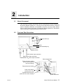
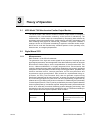
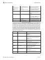
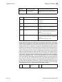
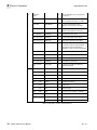
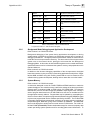
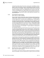
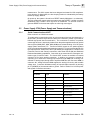
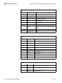


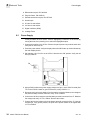
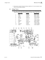
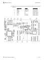
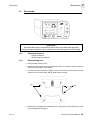
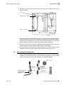
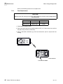
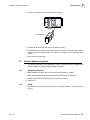
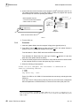


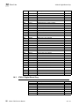

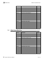

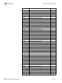
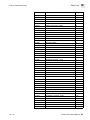
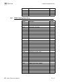
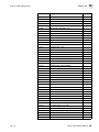
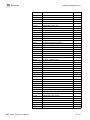
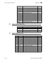


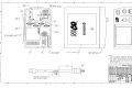
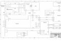
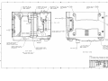
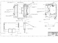

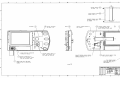
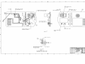
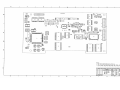

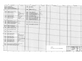
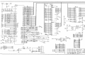
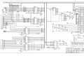
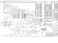
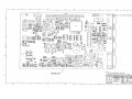
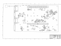
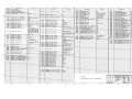
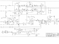
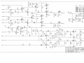
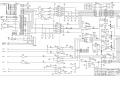
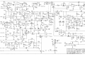
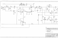
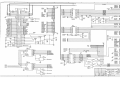
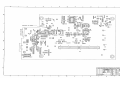
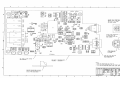
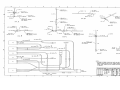
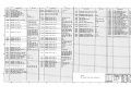
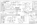
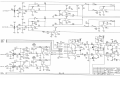
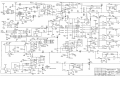

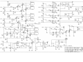


![10780-90006 - 10780A Laser Receiver for 5501A [Prefix 1948] (Mar](http://vs1.manualzilla.com/store/data/006009643_1-6e2f54ebb2199ef6df634558ba4c1bb6-150x150.png)