1
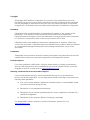
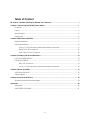
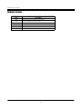
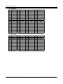
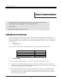
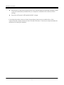
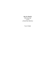
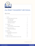
FabIATech Corporation
IPC Solution
Website: http://www.fabiatech.com
Email: [email protected]
FB-1602 PC/104 VGA/LCD
Display Module User’s Manual
Mar 2002
Version: 1.0
Part Number: FB1602
Copyright
©Copyright 2001FabIATech Corporation. The content of this publication may not be
reproduced in any part or as a whole, transcribed, stored in a retrieval system, translated
into any language, or transcribed in any form or by any means, electronic, mechanical,
magnetic etc. or otherwise without the prior written permission of FabIATech Corporation.
Disclaimer
FabIATech makes no representation of warranties with respect to the contents of this
publication. In an effort to continuously improve the product and add features,
FabIATech reserves the right to revise the publication or change specifications contained
in it from time to time without prior notice of any kind from time to time.
FabIATech shall not be reliable for technical or editorial errors or omissions, which may
occur in this document. FabIATech shall not be reliable for any indirect, special, incidental
or consequential damages resulting from the furnishing, performance, or use of this
document.
Trademarks
Trademarks, brand names and products names mentioned in this publication are used for
identification purpose only and are the properties of their respective owners.
Technical Support
If you have problems or difficulties in using the system board, or setting up the relevant
devices, and software that are not explained in this manual, please contact our service
engineer for service, or send email to [email protected].
Returning Your Board For Service & Technical Support
If your board requires servicing, contact the dealer from whom you purchased the
product for service information. You can help assure efficient servicing of your product by
following these guidelines:
!
A list of your name, address, telephone, facsimile number, or email address where
you may be reached during the day
!
Description of you peripheral attachments
!
Description of you software (operating system, version, application software, etc.)
and BIOS configuration
!
Description of the symptoms (Extract wording any message)
For updated BIOS, drivers, manuals, or product information, please visit us at
www.fabiatech.com
ii
Table of Content
FB-1602 PC/104 VGA/LCD Display Module User’s Manual ................................................................... i
Chapter 1 Introducing the FB1602 System Board.................................................................................. 1
Overview...............................................................................................................................................1
Layout....................................................................................................................................................3
Specifications .......................................................................................................................................4
Packing List ...........................................................................................................................................5
Chapter 2 Hardware Installation ............................................................................................................ 7
Before Installation ................................................................................................................................7
Hardware Features..............................................................................................................................8
CN1 & J1: LCD Connector and inverter board connector ................................................9
DB1& CN2: CRT connector ....................................................................................................10
CN3, CN4: PC/104 Connector ..............................................................................................10
Chapter 2 Installing CRT and LCD Monitors ......................................................................................... 12
LCD FLAT PANEL DISPLAY ..................................................................................................................12
CRT & LCD DISPLAY ...........................................................................................................................14
DB1: CRT connector................................................................................................................14
CN1 & J1: LCD Connector and inverter board connector ..............................................15
Chapter 3 Driver and Utility ................................................................................................................... 16
VGA Driver for Win 31........................................................................................................................16
Utility Program ....................................................................................................................................17
Chapter 4 Technical Reference ........................................................................................................... 18
Trouble Shooting for Error Messages ...............................................................................................18
Appendix................................................................................................................................................ 20
Dimension ...........................................................................................................................................20
SUPPORTED LCD PANEL.....................................................................................................................21
iii
iv
FabIATech Corporation
Chapter 1 Introducing the FB1602 System Board
Overview
The FB1602 is a PC/104 VGA/LCD module. This user’s manual provides information on the
physical features and installation of the FB1602.
The FB1602 is supports CRT color monitor, STN, Dual-Scan, TFT, monochrome and color panels.
It can be connected to create a compact video solution for the industrial environment. 512
K/1MB of RAM on-boarded allows a maximum CRT resolution of 1280X1024 and a LCD resolution
of 640X480 with 64K colors.
For different VGA display modes, your monitor must possess certain characteristics for display the
mode you want. There is the table to list the standard VGA display modes for the module and
monitor information, which supports them.
Model#
(Hex)
0+, 1+
0+, 1+
0+, 1+
2+, 3+
2+, 3+
2+, 3+
4
5
6
7+
7+
7+
13
Display
Mode
Text
Text
Text
Text
Text
Text
Graphics
Graphics
Graphics
Text
Text
Text
Graphics
Colors
16
16
16
16
16
16
4
4
2
Mono
Mono
Mono
256
Text
Display
40x25
40x25
40x25
80x25
80x25
80x25
40x25
40x25
80x25
80x25
80x25
80x25
40x25
Font
Size
9x16
8x14
8x8
9x16
8x14
8x8
8x8
8x8
8x8
9x16
9x14
9x8
8x8
Pixel
Resolution
360x400
320x350
320x200
720x400
640x350
640x200
320x200
320x350
640x200
720x400
720x350
720x350
320x200
Dot Clock
(MHz)
50/28.322
56/25.175
56/25.175
56/28.322
56/25.175
56/25.175
56/25.175
56/25.175
56/25.175
56/25.322
56/25.322
56/25.322
56/25.175
Horizontal
Freq. (KHz)
31.5
31.5
31.5
31.5
31.5
31.5
31.5
31.5
31.5
31.5
31.5
31.5
31.5
Supported Video Modes – VGA Standard
1
Vertical
Freq. (Hz)
70
70
70
70
70
70
70
70
70
70
70
70
70
FabIATech Corporation
Model
# (Hex)
20
22
24
24I
30
32
34
34I
40
41
50
60
61
71,75I
78
79
Display Mode Colors
4 Bit Linear
4 Bit Linear
4 Bit Linear
4 Bit Linear
8 Bit Linear
8 Bit Linear
8 Bit Linear
8 Bit Linear
15 Bit Linear
16 Bit Linear
24 Bit Linear
Text
Text
16
16
16
16
256
256
256
256
32K
64K
16
16
16
Text
Display
80x30
100x37
128x48
128x48
80x30
100x37
128x48
128x48
80x30
80x30
80x30
132x35
132x50
Packed Pixel
Packed Pixel
16
256
80x25
80x30
Font
Size
8x16
8x16
8x16
8x16
8x16
8x16
8x16
8x16
8x16
8x16
8x16
8x16
8x16
Pixel
Resolution
640x480
800x600
1024x768
1024x768
640x480
800x600
1024x768
1024x768
640x480
640x480
640x480
1056x400
1056x400
8x16
8x16
640x400
640x480
Dot Clock Horizontal
(MHz)
Freq. (KHz)
56/25.175
31.5
56/40.000
37.5
65/65.000
48.5
65/44.900
35.5
56/25.175
31.5
56/40.000
37.5
65/65.000
48.5
64/44.900
35.5
65/50.350
31.5
65/50.350
31.5
65/65.000
27.1
65/40.000
30.5
65/40.000
30.5
65/44.900
35.5
56/25.175
31.5
56/25.175
31.5
Note: The “I” in the mode #Column indicates “Interlaced”
Supported Video Modes – Extended Resolution
2
Vertical
Freq. (Hz)
60
60
60
43
60
60
60
43
60
60
51.6
68
68
43
70
60
FabIATech Corporation
Layout
CN1
CN2
J1
DB1
CN3
CN4
3
FabIATech Corporation
Specifications
#
IBM-VGA hardware compatible
#
Supports CRT color monitors and STN, TFT, Dual-Scan STN, monochrome and color panels.
#
CRT resolution up to 1280x1024x16 colors.
#
LCD resolution up to 640x480x64K colors.
#
Chips and Technology F65545 Chipset.
#
Simultaneous CRT and LCD operation.
#
Operating temperature 0 degree C to 60 degree C
#
Up to 95% Humidity non-condensing.
#
Power Req.: +5v only 0.3A maximum.
#
PC/104 form-factor (92x97mm/3.6”x3.8”).
4
FabIATech Corporation
Packing List
Upon receiving the package, verify the following things. Should any of the mentioned happens,
contact us for immediate service.
•
Unpack and inspect the FB1602 package for possible damage that may occur during the
delivery process.
•
Verify the accessories in the package according to the packing list and see if there is
anything missing or incorrect package is included.
•
If the cable(s) you use to install the FB1602 is not supplied from us, please make sure the
specification of the cable(s) is compatible with the FB1602 system board.
Note: after you install the FB1602, it is recommended that you keep the diskette or
CD that contains drivers and document files, document copies, and
unused cables in the cartoon for future use.
The following lists the accessories that may be included in your FB1602 package. Some
accessories are optional items that are only shipped upon order.
•
One FB1602 PC/104 VGA /LCD display board
•
One compact disc containing manual file in PDF format and necessary drivers and
utilities
5
FabIATech Corporation
6
FabIATech Corporation
Chapter 2 Hardware Installation
This chapter introduces the FB1602 board connectors and then guides you to apply them for field
application.
Before Installation
Before you install the PC/104 VGA/LCD board, make sure you follow the following descriptions.
1. Before removing the board from its anti-static bag, wear an anti-static strap to prevent the
generation of Electricity Static Discharge (ESD). The ESD may be created from human body
that touches the board. It may do damage to the board circuit.
2. Once you have installed the VGA card into the CPU’s PC/104 bus, you can start connect
internal cables. The internal cables are wire leads with plastic female connector that
attached to the card’s connectors. The VGA card’s connectors have many numbers of pins
and are the points of contact between the CPU card and other parts of the computer.
3. When you connect the LCD connectors, be careful with the pin orientations.
7
FabIATech Corporation
Hardware Features
The following lists the connectors and jumpers to install the FB1602.
Item
CN1
CN2
CN3
CN4
J1
DB1
Description
DF12 40–PIN LCD interface connector
10-pin header for VGA monitor
64 pin PC/104 connector bus A & B
40 pin PC/104 connector bus C & D
5-pin external header for inverter board
CRT connector
8
FabIATech Corporation
CN1 & J1: LCD Connector and inverter board connector
CN1 is 24-bit LCD interface connector and J1 is for inverter board connector.
CN1
CN1
CN2
J1
J1
DB1
CN3
1
CN4
5
Pin
1
3
5
7
9
11
13
15
17
19
21
23
25
27
29
31
33
35
37
39
CN1
+5V
Ground
NC
FP0
FP2
FP4
FP6
FP8
FP10
FP12
FP14
FP16
FP18
FP20
FP22
Ground
SHFCLK
DE
ENABLK
Pin
2
4
6
8
10
12
14
16
18
20
22
24
26
28
30
32
34
36
38
40
CN1
+5V
Ground
Ground
FP1
FP3
FP5
FP7
FP9
FP11
FP13
FP15
FP17
FP19
FP21
FP23
Ground
FP
LP
ENAVEE
9
PIN
1
2
3
4
5
Signal
+12 V
GND
ENABLK
N.C
+5 V
FabIATech Corporation
DB1& CN2: CRT connector
The CRT is use to a standard CRT connector (DB1).
CN2
1
2
9
10
CN1
CN2
J1
DB1
CN3
5
1
15
10
CN4
DB1
DB1
1
2
3
5,10
Signal
RED
GREEN
BLUE
Digital Ground
CN2 DB1
Signal
CN2
1
6,7,8 Analog Ground
6
3
13
HSYNC
9
5
14
VSYNC
7
4
Case Case Ground
6
CN3, CN4: PC/104 Connector
Locate the PC/104 bus connector on the FB1602 VGA module and its counterpart on the CPU
card or board.
CN3 – BUS A & B
CN1
CN2
J1
CN4 – BUS C & D
DB1
CN3
CN4
10
FabIATech Corporation
PC/104 A&B Pin
Pin
Signal
A1
-IOCHK
A2
SD7
A3
SD6
A4
SD5
A5
SD4
A6
SD3
A7
SD2
A8
SD1
A9
SD0
A10
IORDY
A11
AEN
A12
SA19
A13
SA18
A14
SA17
A15
SA16
A16
SA15
Pin
A17
A18
A19
A20
A21
A22
A23
A24
A25
A26
A27
A28
A29
A30
A31
A32
PC/104 C& D Pin
Signal
Pin
C1
GND
C2
SBHE
C3
LA23
C4
LA22
C5
LA21
C6
LA20
C7
LA19
C8
LA18
C9
LA17
C10 MEMR#
Pin
Signal
C11 MEMW#
C12
SD8
C13
SD9
C24
SD10
C25
SD11
C26
SD12
C27
SD13
C28
SD14
C29
SD15
C20
KEY
Signal
SA14
SA13
SA12
SA11
SA10
SA9
SA8
SA7
SA6
SA5
SA4
SA3
SA2
SA1
SA0
Ground
Pin
B1
B2
B3
B4
B5
B6
B7
B8
B9
B10
B11
B12
B13
B14
B15
B16
Signal
Ground
RSTDRV
+5V
IRQ9
-5V (*1)
DRQ2
-12V (*1)
-ZWS
+12V
Key1
-MEMW
-MEMR
-IOW
-IOR
-DACK3
DRQ3
Pin
B17
B18
B19
B20
B21
B22
B23
B24
B25
B26
B27
B28
B29
B30
B31
B32
Pin
Signal
Pin
D1
Ground
D11
D2 MEMCS16# D12
D3
IOCS16# D13
D4
IRQ10
D14
D5
IRQ11
D15
D6
IRQ12
D16
D7
IRQ15
D17
D8
IRQ14
D18
D9
DACK#0
D19
D10
DREQ0
D20
11
Signal
-DACK1
DRQ1
-REFSH
BUSCLK
IRQ7
IRQ6
IRQ5
IRQ4
IRQ3
-DACK2
TC
ALE
+5V
OSC
Ground
Ground
Signal
-DACK#5
DREQ5
DACK#6
DREQ6
DACK#7
DREQ7
VCC
MASTER#
GND
GND
FabIATech Corporation
Chapter 2 Installing CRT and LCD Monitors
This chapter describes the configuration and installation procedure of LCD and CRT displays.
Both CRT and LCD displays may be used at the same time. However, each type of LCD requires
different BIOS. This section describes the configuration and installation procedure using LCD
display. Skip this section if you are using CRT monitor only.
• LCD Flat Panel Display
• CRT & LCD Display
LCD FLAT PANEL DISPLAY
The BIOS default for NEC NL6448AC33-13 LCD panel. And then set your system properly and BIOS
module for the right LCD panel you are using. Each model of LCD requires different BIOS in order
to work properly. If the BIOS you need is not on our website www.fabiatech.com, then you can
contact fabia send us a sample of the panel you will be using and we will send it back to you
with the new BIOS.
The following shows the block diagram of using FB1602 for LCD display.
Inverter Board
Transmitter Board
FB4608A
LCD Connector
TFT / STN LCD
FB1602 PC/104
VGA/LCD
Board
LCD Panel Block Diagram
12
FabIATech Corporation
LVDS Transmitter Board
FB4620/FB4600
Receiver Board
Inverter Board
FB4612A
FB4601
LCD Connector
LVDS TFT LCD
FB1602 PC/104
VGA/LCD
Board
LVDS Link Diagram
The block diagram shows that FB1602 till needs components to be used with a LCD panel. The
transfer board (FB4608A) provides the control for the brightness and the contrast of the LCD
panel while inverter board is the one that supplies the high voltage to drive the LCD panel. The
FB4608A, FB4600/01 and FB4620/21 are available from FabIATech with all the necessary cables.
NOTE: Be careful with the pin orientation when installing connectors and the cables. A
wrong connection can easily destroy your LCD panel. The pin 1 of the cable
connectors is indicated with a sticker and the pin1 of the ribbon cable usually has
a different color.
13
FabIATech Corporation
CRT & LCD DISPLAY
The FB1602 supports a CRT colored monitor and a LCD. It can be connected to create a
compact video solution for the industrial environment. 512KB /1MB(Optional) of RAM onboarded allows a maximum CRT resolution of 1024X768 with 256 colors and a LCD resolution of
640X480 with 64K colors.
DB1: CRT connector
The CRT is use to a standard CRT connector (DB1).
CN1
DB1
CN2
5
1
15
10
J1
(Front View)
DB1
CN3
DB1
1
2
3
5,10
CN4
Signal
RED
GREEN
BLUE
Digital Ground
CN2 DB1
Signal
CN2
1
6,7,8 Analog Ground
6
3
13
HSYNC
9
5
14
VSYNC
7
4
Case Case Ground
6
14
FabIATech Corporation
CN1 & J1: LCD Connector and inverter board connector
CN1 is 24-bit LCD interface connector and J1 is for inverter board connector.
CN1
CN1
CN2
J1
DB1
CN3
J1
CN4
1
5
Pin
CN2
Pin
CN2
1
3
5
7
9
11
13
15
17
19
21
23
25
27
29
31
33
35
37
39
+5V
Ground
NC
FP0
FP2
FP4
FP6
FP8
FP10
FP12
FP14
FP16
FP18
FP20
FP22
Ground
SHFCLK
DE
ENABLK
2
4
6
8
10
12
14
16
18
20
22
24
26
28
30
32
34
36
38
40
+5V
Ground
Ground
FP1
FP3
FP5
FP7
FP9
FP11
FP13
FP15
FP17
FP19
FP21
FP23
Ground
FP
LP
ENAVEE
15
PIN
1
2
3
4
5
Signal
+12 V
GND
ENABLK
N.C
+5 V
FabIATech Corporation
Chapter 3 Driver and Utility
The FB1602 provides a CD ROM includes the manual files (a complete manual file) and the
required utility files.
VGA Driver for Win 31
Step 1:
To install the VGA driver, insert the CD ROM into the CD ROM device, and enter
DRIVER>VGA>Ct65545>. If your system is not equipped with a CD ROM device,
copy the VGA driver from the CD ROM to a 1.44” diskette.
Step 2:
Execute setup.exe file.
Step 3:
The screen shows the chip type. Press any key to enter the main menu.
Step 4:
There are some items for choice to setup. Please choose the <Windows Version
3.1> item notice the function key defined. Press [ENTER] selected the <All
Resolutions>, when this line appears [*] symbol, which means this item is selected.
Pressing [End] starts to install.
Step 5:
The screen will show the dialog box, demanding the user to type the WIN31’s path.
The default is C:\WINDOWS.
Step 6:
As the setup is completed, the system will generate the message as follows.
Installation is done!
Change to your Windows directory and type SETUP to run the Windows Setup
program. Choose one of the new drivers marked by an *. Please refer to the
User’s Guide to complete the installation.
16
FabIATech Corporation
Step 7:
Press the [Esc] key to return to the main menu, and re-press the [Esc] key to return
to the DOS mode.
Step 8:
In the WIN31, you can find the <Chips CPL> icon located in the {CONTROL PANEL}
group.
Step 9:
Adjust the <Refresh Rate>, <Cursor Animation>, <Font size>, <Resolution>, and <Big
Cursor>.
Utility Program
The utility allows you to select the display type from the following:
•
•
•
CT.COM:
CRT only
FP.COM:
LCD (Flat Panel) only
SM.COM:
Both CRT and LCD (Flat Panel)
17
FabIATech Corporation
Chapter 4 Technical Reference
This section outlines the errors that may occur when you operate the system,
and also gives you the suggestions on solving the problems.
Topic include:
# Trouble Shooting for Error Beep Code
Trouble Shooting for Error Messages
The following information informs the error beep code and troubleshooting. Please adjust your
systems according to the messages below. Make sure all the components and connectors are
in proper position and firmly attached. If the errors still exist, please contact with your distributor
for maintenance.
!
Error Beep Code
There are three possible beep codes produced by the BIOS during POST listed below:
Beep Code
1 long followed by 2 short beeps
1 long followed by 3 short beeps
1 long followed by 4 short beeps
1 long followed by 8 short beeps
!
Error Condition
CMGA card failure
RAM test failure
DAC test failure
VGA initialized failure
Troubleshooting
If you have problems after installation, check the following to determine the cause.
#
Ensure that all cable are properly connected, all plugs are firmly seated in their sockets.
Check to see if the VGA and LCD are firmly seated in its bus PC/104. Be sure it is not making
contact with any other cards in the system.
#
Ensure that the display monitor is properly connected to computer. Be sure the display
monitor and your system’s power supply is operating properly (i.e. FAN operates, system
power light come on). Power OFF the computer system and all other connector devices
before checking the following:
18
FabIATech Corporation
#
Ensure that no other switch setting on the CPU card has been accidentally changed. Refer
to the documentation provided with you computer to determine the corrector switch
settings
#
Ensure the LCD panel’s VEE and BACKLIGHT voltage
If checking these items does not locate the problem, there may be a malfunction of the
computer system, display monitor or the VGA and LCD board. Consult you computer dealer for
assistance in locating the problem
19
FabIATech Corporation
Appendix
Dimension
8.9
73.7
85.7
95.9
5.1
90.2
5.1
80
Unit: mm
20
3.5
FabIATech Corporation
SUPPORTED LCD PANEL
This VGA board can provide the total solution with inverter board for the following list of
standard LCD panel using the PC/104 VGA module. Consult your FabIATech representative
for new developments, when using other models of standard LCD panels in the market.
NO.
Manufacture
Model No.
Description
1
NEC
NL-6448AC30-10
TFT 9.4”
2
NEC
NL-6448AC32-10
TFT 10.2”
3
NEC
NL-6448AC33-10
TFT 10.4”
4
TOSHIBA
LTM10C209
TFT 10.4”
21