1
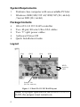
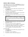
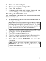
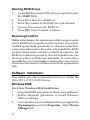
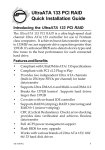
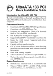
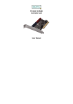
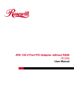
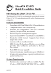
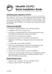
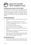
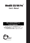
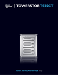
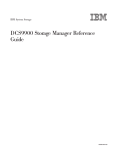
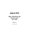
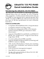
UltraATA 133 PCI RAID
Quick Installation Guide
Introducing the UltraATA 133 PCI RAID
The UltraATA 133 PCI RAID is a ultra high-speed dual
channel Ultra ATA/133 controller for use in Pentium
class computers. It achieves burst data transfer rates up
to 133MB/sec and supports drive capacities greater than
137GB. It's enhanced BIOS auto-detects device types and
fine tunes to the best performance for each connected
hard drive.
Features and Benefits
•
•
•
•
•
•
•
•
•
•
•
Compliant with UltraDMA6 ATA/133 specifications
Compliant with PCI v2.2 Plug-n-Play
Provides two independent Ultra ATA channels
(built-in 256-byte FIFOs per channel) for faster
data transfer
Supports Ultra DMA 0-6 and Multi-word DMA 0-2
Breaks the 137GB barrier! Supports hard drives
larger than 137GB
Co-exists with on-board IDE controller
Supports RAID 0 (striping), RAID 1 (mirroring) and
RAID 0+1 (mirror+striping)
CRC (Cyclical Redundancy Check) error-checking
provides data verification and achieves flawless
data transfer
Full ACPI power management support
Flash BIOS for easy upgrade
Works with various brands of Ultra ATA 133/100/
66/33 hard disk drives
04-0369B
1
System Requirements
•
•
Pentium class computer with one available PCI slot
Windows 98SE/ME/NT 4.0/2000/XP (32-/64-bit)
/Server 2003 (32-/64-bit)
Package Contents
•
•
•
•
•
UltraATA 133 PCI RAID controller
Two 40-pin/80-wire Ultra ATA cables
Two "Y" split power cables
Software/Driver CD
Quick Installation Guide
Layout
Pin1
IDE2
Pin1
IDE1
HDD
Activity
LED
Jumper On
(do not remove)
Figure 1. UltraATA 133 PCI RAID layout
Note: For proper operation of the UltraATA 133 PCI
RAID, the jumper must remain on.
2
Hardware Installation
General instructions for installing the card are provided
below. Since the design of computer cases and
motherboards vary, refer to your computer’s reference
manual for further information, if needed.
Static Electricity Discharge may permanently damage
your system. Discharge any static electricity build up in
your body by touching your computer’s case for a few
seconds. Avoid any contact with internal parts and
handle cards only by their external edges.
1.
2.
3.
4.
5.
6.
Turn OFF the power to your computer and any
other connected peripheral devices.
Unplug the power cord from the back of the
computer.
Remove your computer’s cover.
Remove the slot bracket from an available PCI slot.
To install the card, carefully align the card's bus
connector with the selected PCI slot on the
motherboard. Push the board down firmly, but
gently, until it is well seated.
Replace the slot bracket's holding screw to secure
the card.
Device Connection
The UltraATA 133 PCI RAID is a dual channel Ultra ATA
133 controller that supports up to four IDE hard disk
drives. To achieve maximum performance and
compatibility we suggest using identical hard drives in
building your RAID sets.
3
In any given RAID set, it's best to install the hard drives
on separate channels, either Master to Master or Slave to
Slave. For example, if you are setting up a RAID set with
two hard drives, install the first drive on IDE1 as Master
and the second on IDE2 as Master. Use the same concept
for multiple hard drives.
Note: Only the 40-pin/80-wire UltraATA cable can
achieve hard disk UDMA 133 performance. When
attaching only two hard drives it is recommended
that they be connected on separate IDE channels.
1.
2.
If you plan to install two hard disk drives on the
IDE1 channel, make sure to configure one drive as
Master and the drive as Slave. Follow the hard drive
manufacturer’s instructions for the correct jumper
setting. The same rule must be followed for
connecting hard disk drives to the IDE2 channel.
Attach one end of the included Ultra ATA cable to
the IDE1 connector on the board. Make sure pin 1
on the cable (indicated by the stripe) matches pin 1
on the IDE1 connector.
Stripe
Pin 1
Figure 2. Connecting the Cable to the On-Board Connector
4
3.
Install the hard disk drive to your computer. Attach
the end connector of the Ultra ATA cable to the
connector on the hard disk drive. Make certain that
pin 1 on the cable (indicated by the stripe) matches
pin 1 on the hard disk drive’s connector. The same
procedure applies when making connection to IDE2.
Note: The ribbon cable has two connectors. If you
have one hard disk drive, connect it to the end
connector of cable and set it as master. If you have
a second hard disk drive, connect it to the middle
connector of cable and set it as slave.
End Connector
Middle Connector
Internal
Drive 1
Internal
Drive 2
(If Any)
Drive 1
Drive 2
IDE2
IDE1
UltraATA 133 PCI RAID
Figure 3. Connecting Internal Drives
4.
Reconnect the system power and other peripherals
to your computer.
RAID Arrays
RAID Arrays are setup in the UltraATA 133 PCI RAID
BIOS. Find your RAID set and follow the steps in the
order in which they appear.
5
RAID 0 (Striping)
This RAID array to be used on New/Blank hard drives.
Striping will destroy existing data on the hard drive.
For Manual Setup
1. As the BIOS boots press F3 when prompted to enter
the RAID BIOS.
2.
At the next screen press F2 to form a RAID set.
3.
Press F1 to create RAID 0.
4. Choose the chunk size to be used in the RAID set
(64 is recommended).
5. Choose the number of hard drives in your stripe set.
6. Assign the hard drives to be used. For optimal
performance, alternate hard drives from seperate
IDE channels.
7.
After all hard drives are entered, press Y to create
the RAID set.
8. Press ESC to exit the RAID BIOS and boot your
computer.
9.
Continue with Fdisk and Format steps as if you are
installing a conventional hard drive.
For Auto Setup
1.
As the BIOS boots press F3 when prompted to enter
the RAID BIOS.
2.
Press F2 to create a RAID set.
3. Press F1 to create a Stripe set.
4.
Press A for Auto Setup.
5.
Enter the number of hard drives in the stripe set.
6. Press Y to accept the configuration.
7. Configure another RAID set or press ESC to reboot.
6
RAID 1 (Mirror)
For Manual Setup
For New/Blank hard drives
1.
As the BIOS boots press F3 when prompted to enter
the RAID BIOS.
2. At the next screen press F2 to form a RAID set.
3. Press F2 to create RAID 1. In a Mirror set the source
drive needs to be equal to or smaller than the
destination drive. For optimal performance the
source drive and destination drive should be on
separate IDE channels.
4.
Answer N to Auto Setup.
5.
Assign Source drive, then assign Destination drive.
6.
Answer N when asked to Copy from Source to
Destination.
7.
Answer Y to Enable Auto-Rebuild.
8.
When asked Are you Sure?, press Y to accept .
9.
Press ESC to exit the RAID BIOS and boot the
computer.
10. Continue with Fdisk and Format steps as if you
were installing a conventional hard drive.
For Existing Hard Drives with Data
1.
As the BIOS boots press F3 when prompted to enter
the RAID BIOS.
2. Press F2 to enter the RAID setup screen.
3.
Press F2 to form Raid set 1 (mirror).
4. Answer N to Automatic setup.
5.
Assign Source drive, then assign Destination drive.
6.
Press Y to copy from Source to Destination drive.
7.
Press N to Offline copy.
7
8.
Answer Y to Enable Auto-Rebuild.
9.
When asked Are You Sure?, press Y to accept.
10. Press ESC to exit the RAID BIOS. Ignore the BIOS
error message and continue booting. The mirror
rebuilds automatically.
For Auto Setup
Use this setup on New/Blank hard drives only.
1.
2.
3.
4.
5.
6.
7.
As the BIOS boots press F3 when prompted to enter
the RAID BIOS.
Press F2 to create a RAID set.
Press F2 to create a Mirror set.
Press Y to use Auto setup.
Press Y to accept the configuration.
Configure another RAID set or press ESC to reboot.
Continue with Fdisk and Format steps as if you
were installing a conventional hard drive.
Creating a SPARE Drive
When a hard drive failure occurs in a mirror set, the autorebuild feature enables a drive designated as SPARE to
become the new member of the mirror set.
1.
As the BIOS boots press F3 when prompted to enter
the RAID BIOS.
2.
Press F3 to create a spare drive.
3.
Enter the drive number of the hard drive.
4.
Press Y to confirm your choice. The spare drive will
be created and listed as the last set.
5.
Press ESC to exit the RAID BIOS.
The SPARE drive will not be seen by Windows, however,
it remains in the background waiting to rebuild the
mirror in the event of a hard drive failure.
8
Rebuilding a Failed Mirror Set
If a SPARE drive was not configured, the steps below will
guide you in rebuilding a failed mirror set.
1.
2.
3.
4.
5.
6.
7.
8.
9.
10.
11.
12.
13.
14.
15.
16.
17.
As the BIOS boots press F3 when prompted to enter
the RAID BIOS.
Press F1 to dissolve an Array.
Press the number of the Mirrored array to be
dissolved.
Press Y to confirm. Be sure you delete the correct Array.
Press ESC to exit the RAID BIOS, then immediately
turn off the computer.
Replace the bad drive with a new hard drive of
equal or greater size, then restart the computer.
During boot press F3 to enter the RAID BIOS.
Press F2 to Create an Array.
Press F2 to create a Mirrored Array.
Answer N for Automatic setup.
Enter the number of the SOURCE (good) drive.
Enter the number of the DESTINATION (new)
drive.
Answer Y to copy from Source to Destination drive.
Answer N to decline Offline Copy.
Answer Y to enable Auto-rebuild.
When asked Are You Sure?, Press Y to accept.
Press ESC to exit the RAID BIOS and reboot the
computer.
9
RAID 0+1 (Mirror+Striping)
This RAID array to be used on New/Blank hard drives
only, striping destroys existing data on the hard drive.
RAID 0+1 requires four hard drives.
For Manual Setup
1. As the BIOS boots press F3 when prompted to enter
the RAID BIOS.
2.
At the next screen press F2 to form a RAID set.
3.
Press F3 to create RAID 0+1.
4.
Choose the chunk size by pressing the appropriate
number key (64 is recommended).
5.
Enter the first Source drive, then enter the second
source drive.
Note: To optimize performance, configure both
source drives to be from different channels and
configure both destination drives to be from different
channels.
6.
7.
8.
9.
Enter the first destination drive, then enter the second
destination drive.
Enter Y to accept the RAID configuration.
On the following screen press ESC to exit the RAID
configuration utility and reboot the computer.
Continue with Fdisk and Format steps as if you
were installing a conventional hard drive.
For Auto Setup
1. As the BIOS boots press F3 when prompted to enter
the RAID BIOS.
2.
Press F2 to create a RAID set.
3. Press F3 to create a Mirrored-Striped set.
10
4.
5.
6.
7.
Press A to Auto configure.
Press Y to accept the configuration.
Press ESC to reboot.
Continue with Fdisk and Format steps as if you
were installing a conventional hard drive.
Rebuilding a Failed RAID 0+1 Set
The steps below will guide you in rebuilding a failed
Mirrored-Stripe set.
1.
Replace the failed drive with one of identical size or
of larger capacity.
Note: It is recommended to replace the bad drive
with an identical drive, or with a drive of the same
make. In all cases, the replacement drive must be of
equal or larger capacity than the bad drive.
2.
3.
4.
5.
6.
Start the computer and during boot press F3, when
prompted, to enter the RAID BIOS.
Press F3 to assign a Spare drive.
Press the number corresponding to the new drive.
When asked Are You Sure? Press Y to accept.
Press ESC to exit the RAID BIOS and reboot the
computer.
Note: Ignore the error message displayed by the
RAID BIOS and continue booting. The mirror will
rebuild automatically.
11
Deleting RAID Arrays
1.
2.
3.
4.
5.
As the BIOS boots press F3 when prompted to enter
the RAID BIOS.
Press F1 to dissolve a RAID set.
Enter the number of the RAID set to be deleted.
Answer Y to remove the RAID set.
Press ESC when finished to reboot.
Resolving Conflicts
If after a disk failure, the replacement disk was previously
part of a RAID set (or used in another system), it may have
conflicting metadata, specifically in reference to the drive
connection information. If so, this will prohibit the RAID
set from being either created or rebuilt, in order for the
RAID set to function properly, this old metadata must be
first overwritten with the new metadata. To resolve this,
press F4, the correct metadata, including the correct drive
connection information, will be written to the replacement
disk.
Software Installation
This section provides information on how to install the
UltraATA 133 PCI RAID drivers.
Windows 98SE
For A New Windows 98SE Installation
1.
Setup the RAID array prior to Windows installation.
2.
Follow Microsoft procedures to install Windows
98SE accordingly.
3. Once Windows has installed and booted, right click
My Computer and click Properties. Select Device
Manager tab.
12
4.
Double click PCI RAID controller listed under
Other Devices.
5.
Select Driver tab, then click Update Driver button.
6.
Insert the driver CD, then click Next.
7. Select Search for the better driver ... and click Next.
8.
Check Specify a location, uncheck the other boxes,
type in D:\32bit (change D: to match CD-ROM),
then click Next. Click Next again.
9.
Click Finish, remove the driver CD, then click Yes to
restart Windows to complete the installation.
When Windows resumes, go to Medley GUI on page 22
and install the RAID monitoring utility.
For Existing Windows 98SE Installation
1.
Setup the RAID array prior to driver installation and
boot up to Windows.
2. At the Add New Hardware Wizard, click Next to
continue.
3.
Select Search for the best driver for your device,
then click Next.
4.
Check Specify a location, uncheck the other boxes,
type in D:\32bit (change D: to match CD-ROM),
then click Next. Click Next again.
5. Click Finish, remove the driver CD, then click Yes to
restart Windows to complete the installation.
When Windows resumes, go to Medley GUI on
page 22 and install the RAID monitoring utility.
13
Windows ME
For A NewWindows ME Installation
1.
Setup the RAID array prior to Windows installation.
2.
Follow Microsoft procedures to install Windows
ME accordingly.
3.
Once Windows has installed, right click My
Computer and click Properties. Select Device
Manager tab.
4.
Double click PCI RAID controller listed under
Other Devices.
5.
Select Driver tab and click Update Driver button.
6.
Insert the driver CD, select Automatic search for a
better driver (Recommended), then click Next.
7.
Click Finish, remove the driver CD, then click Yes to
restart Windows to complete the installation.
When Windows resumes, go to Medley GUI on page 22
and install the RAID monitoring utility.
For Existing Windows ME Installation
1.
Setup the RAID array prior to driver installation and
boot up to Windows.
2.
At the Add New Hardware Wizard, insert the driver
CD.
3.
Select Automatic search for a better driver
(Recommended), then click Next.
4.
Click Finish, remove the driver CD, then click Yes to
restart Windows to complete the installation.
To Verify Windows 98SE/ME Installation
1.
2.
14
Right click My Computer, click Properties, then
click Device Manager.
Double click SCSI Controllers, Silicon Image Sil
0680 Ultra-133... Controller should be displayed.
3.
Highlight Silicon Image Sil 0680 Ultra-133...
Controller and click Properties. A message This
device is working properly is displayed, the driver has
been correctly installed.
Windows NT 4.0
For A New Windows NT 4.0 Installation
A new installation of Windows NT 4.0 requires a floppy
disk for the driver installation. To make this floppy disk,
copy the contents of the 32bit folder, found on the driver
CD, onto a blank floppy disk then follow the directions
below.
1.
2.
3.
Setup the RAID array prior to NT installation.
Follow Microsoft's NT installation procedure.
When booting from Microsoft Windows NT 4.0 CD,
the following screens will appear.
4.
Screen 1, Setup is inspecting your computer's
hardware configuration, press F6 key to specify
and add the driver.
5.
Screen 2, Windows NT Setup, Setup is loading
files, keep pressing F6 key to add driver.
6.
If screen 3 does not appear for options to Specify
Additional Device then shut off system and repeat
steps 4-5 otherwise continue to step 7.
7.
Insert the driver diskette and press S.
8.
Screen 4, Windows NT Setup, highlight Other and
hit Enter.
9.
Screen 5, Windows NT Setup, make sure driver
diskette is in floppy drive and press Enter.
10. Screen 6, Windows NT Setup, highlight Silicon
Image Ultra-133 Medley ATA RAID Controller
and hit Enter to load driver.
15
11.
Follow on-screen instructions to complete setup for
your NT version.
When Windows installation completes, go to Medley
GUI on page 22 and install the RAID monitoring utility.
For An ExistingWindows NT 4.0 Installation
1. Setup the RAID array prior to driver installation and
boot up to Windows NT.
2.
Double click My Computer/Control Panel/SCSI
Adapters, then click on the "Drivers" tab.
3. Select Add… then Have Disk....
4.
Insert the driver CD, type in D:\32bit (change D: to
match CD-ROM), then click OK.
5. Highlight Silicon Image Sil 0680 Ultra-133 Medley
ATA RAID Controller and click OK.
6.
Click Browse , then click drop down arrow in Look
in. Select CD-ROM drive (Drivers), double click
32bit, click Open, then OK.
7.
Remove the driver CD, close all open Windows,
then restart NT to complete the installation.
When Windows resumes, go to Medley GUI on page 22
and install the RAID monitoring utility.
To Verify Windows NT 4.0 Installation
1.
2.
16
Go to Start / Settings / Control Panel, double click
SCSI Adapters icon.
Highlight Silicon Image Sil 0680 Ultra-133 Medley
ATA RAID Controller from SCSI Adapters listing
and select Properties. A message This device is
working properly is displayed in the dialog box, the
driver has been correctly installed.
Windows 2000
For New Windows 2000 Installation
A new installation of Windows 2000 requires a floppy
disk for the driver installation. To make this floppy disk,
copy the contents of the 32bit folder, found on the driver
CD, onto a blank floppy disk then follow the directions
below.
1.
2.
Setup the RAID array prior to Windows installation.
Follow Microsoft's Windows 2000 installation
procedure.
3.
Restart the computer when prompted.
4. At the Windows 2000 Setup screen, when prompted,
press F6 to install the driver.
5.
When prompted press S to specify the location of
the driver.
6.
Insert the driver diskette, then press Enter.
7.
Silicon Image Ultra-133 Medley ATA RAID
Controller will appear in the box, press Enter.
8.
Press Enter to finish driver installation, then follow
the on-screen instructions to complete Windows
2000 installation.
When Windows installation completes, go to Medley
GUI on page 22 and install the RAID monitoring utility.
For An Existing Windows 2000 Installation
1.
Setup the RAID array prior to driver installation and
boot up to Windows.
2.
At the Found New Hardware Wizard, click Next.
3.
Select Search for a suitable driver for my device
(recommended), then click Next.
4.
Insert the driver CD,check CD-ROM drives, uncheck
the other boxes, click Next, and click Next again.
17
5.
If the Digital Signature Not Found message appears,
click Yes. Our driver has been thoroughly tested in
Windows for stability.
Note: If prompted for Windows 2000 CD-ROM,
insert the CD into your CD-ROM drive and click
OK. Type in D:\I386 (change D: to match your
CD-ROM drive letter), click OK, then Finish.
6.
Click Finish, remove the driver CD, then restart
Windows to complete driver the installation.
When Windows resumes, go to Medley GUI on page 22
and install the RAID monitoring utility.
32- bit Windows XP/Server 2003
For A New 32-bit Windows XP /Server 2003 Installation
A new installation of Windows XP/Server 2003 requires
a floppy disk for the driver installation. To make this
floppy disk, copy the contents of the 32bit folder, found
on the driver CD, onto a blank floppy disk then follow the
directions below.
1.
2.
3.
4.
5.
6.
7.
18
Setup the RAID array prior to Windows installation.
Follow Microsoft's Windows installation procedure.
Restart the computer when prompted by Windows'
installation.
At the Windows Setup screen, when prompted,
press F6 to install the driver.
When prompted press S to specify the location of
the driver.
Insert the driver diskette, then press Enter.
Silicon Image Ultra-133 Medley ATA RAID
Controller will appear in the box, press Enter.
8.
Press Enter to finish driver installation, then follow
the on-screen instructions to complete Windows
installation.
Note: If the Software Installation warning pops up,
click Yes. And if the Hardware Installation warning
pops up, click Yes again. Our driver has been thoroughly
tested for stability and compatibility.
When Windows installation completes, go to Medley
GUI on page 22 and install the RAID monitoring utility
For Existing 32-bit Windows XP /Server 2003 Installation
1.
Setup the RAID array prior to driver installation and
boot up to Windows.
2.
Install the board and boot up in Windows
3.
At the Found New Hardware Wizard:
XP (w/SP1 or earlier)/Server 2003: continue to step #4
4.
XP (w/SP2 or later)/Server 2003 (w/ SP1 or later): select
No, not at this time, then click Next
Insert the driver CD, select Install the software
automatically (Recommended), then click Next.
Note: Most systems will install the driver
automatically after inserting driver CD
5.
If the Windows logo window appears, click
Continue Anyway, then click Finish to complete
the installation. Our driver has been thoroughly tested
for stability and compatibility.
When Windows resumes, go to Medley GUI on page 22
and install the RAID monitoring utility.
19
64-bit Windows XP/Server 2003
For New Windows 64-bit XP/Server 2003 Installation
A new installation of Windows XP/Server 2003 requires
a floppy disk for the driver installation. To make this
floppy disk, copy the contents of the 64bit folder, found
on the driver CD, onto a blank floppy disk then follow the
directions below.
1
Setup the RAID array prior to driver installation and
boot up to Windows. .
2.
Install the board and follow Microsoft procedures
to install Windows accordingly.
3.
Restart your system when prompted during
Windows' installation.
4.
At the Windows Setup screen, press F6 to install the
driver.
5.
Insert the driver diskette. Press S then press Enter.
6.
Select Silicon Image SiI 0680 ATA/133 RAID
Controller (64-bit Extended) and press Enter.
7.
Press Enter to continue and follow on-screen
instructions to complete the installation.
When Windows resumes, go to Medley GUI on page 22
and install the RAID monitoring utility.
For Existing 64-bit Windows XP/Server 2003 Installation
1.
Setup the RAID array prior to driver installation and
boot up to Windows.
2. Install the board and boot up Windows.
3.
At the Found New Hardware Wizard:
XP (w/SP1 or earlier)/Server 2003: continue to step #4
XP (w/SP2 or later)/Server 2003 (w/ SP1 or later): select
No, not at this time, then click Next
20
4.
Insert the driver CD, select Install the software
automatically (Recommended), then click Next.
Note: Most systems will install the driver
automatically after inserting driver CD
5.
Click Finish, remove the driver CD and restart
Windows to complete the installation.
When Windows resumes, go to Medley GUI on page 22
and install the RAID monitoring utility.
To Verify Windows 2000/XP/Server 2003
Installation
1.
2.
Right click My Computer, click Manage, then click
Device Manager.
Double click SCSI and RAID Controllers.
32-bit Windows 2000/XP/Server 2003 :
- You should see Silicon Image Sil 0680 Ultra-133
Medley ATA RAID Controller
3.
64-bit Windows XP/Server 2003 :
- You should see Silicon Image Sil 0680 ATA/133
RAID Controller
Double click each category to display driver
properties. A message This device is working properly
is displayed, the driver has been correctly installed.
21
Medley GUI
The Medley GUI provides significant functionality
including the ability to create and dissolve RAID sets;
Remove a member of a Mirrored or Mirrored-Striped
RAID set; Rebuild a Mirrored RAID set; save, copy, or
send, via e-mail, the current configuration.
Installing Medley GUI
1.
Place the driver installation CD into the CD-ROM
drive.
2.
At the Windows desktop click Start, then Run.
3.
Type D:\Installsiicfg.exe, then click OK.
4.
Click Next, Next, then Finish respectively.
The installation of the Medley GUI is now complete.
Proceed to Using the Medley GUI for operating
instructions.
Using Medley GUI
During the installation process, the Medley GUI was
saved in the Windows Startup folder, a small blue Medley
logo will appear in the right-hand corner of taskbar. To
launch the GUI, simply click on the icon.
Upon launching the GUI, the the first window which
identifies the computer running Medley should appear
similar to the following.
22
Selecting each different component in the configuration
tree provides specific information for that component,
such as the chip.
By selecting a specific channel, either Primary or
Secondary, the following information is reported.
23
Selecting a specific drive reports all pertinent information
to that drive, including Configuration and Disk
Identification information.
24
Selecting Sets reports how many RAID sets have been
created.
By selecting a specific RAID set, such as Set 0 which is the
Striped set, the type of RAID set, the number of members
and stripe size is reported.
25
The Members tab reports the device identification
(corresponding with the information in the BIOS) and the
State of each device.
Besides reporting information, the Members tab of a
mirror set allows the user to remove a specific drive from
that set, as well as add a designated Spare drive to a
Mirrored set that has experienced a disk failure. If more
than one set exists, clicking on each Set in the Configuration
Tree provides specific information for that Set.
26
The device identification, along with the State of each
device is also reported in the Members tab window. Note
that when a Mirrored Set is first created, the State of the
“destination” drive may report as Rebuild for as much as
30-90 minutes depending on the size of the disk.
SMART and Configuration information, as well as Data
Identification is again provided for each Set.
27
Medley Configuration Menu
With Medley running, the small Medley icon should
appear in the bottom right of the computer screen, next to
the clock. By right-clicking on the icon, the user may
configure Medley including customizing the settings for
SMTP, E-mail, Notification, Event Level, Log File, Audio,
and Popup.
SMTP
The SMTP server is the server that is used to send e-mails.
Normally, the network administrator knows what this
name is. Both the name and domain must be entered.
28
E-Mail
The current Medley configuration may be sent via e-mail.
Using the e-mail tab in the Medley Configuration Menu,
the user may set the default e-mail address and subject
line to where the configuration would be sent. This,
however, can be overridden at the time of sending the
email.
Notification
When different types of events occur, Medley may be
configured to send notices to assigned individual e-mail
addresses. Using the Notification tab, all e-mail addresses
desired to receive the notices may be entered.
29
Event Level
There are different types of e-mail notifications that may
be sent which are set with the Event Level tab.
The different levels are:
Disabled - No event logs will be sent
Informational - The following events will be sent:
- Informational
- Warnings
- Errors
Warning - The following events will be sent:
- Warnings
- Errors
Errors - The following events will be sent:
- Errors
30
Log File
The log file is used to store event information received
from all the RAID drivers. The log file is a text file and can
be viewed with Notepad or the Medley GUI. Use the Log
File tab to set where the log file should be stored and the
name of the file as well.
Audio
The user may set different audio alerts for the different
levels of events.
31
Popup
The popup window is a visual notification that an event
occurred. The popup window can be disabled or set to
popup for only certain event levels.
The different levels are:
Disabled - No popup will occur
Informational - The popup window will be displayed
for the following events:
- Informational
- Warnings
- Errors
Warning - The popup window will be displayed for the
following events:
- Warnings
- Errors
Errors - The popup window will be displayed for the
following events:
- Errors
32
Blank Page
33
Blank Page
34
Technical Support and Warranty
QUESTIONS? SIIG’s Online Support has answers! Simply visit our
web site at www.siig.com and click Support. Our online support
database is updated daily with new drivers and solutions. Answers
to your questions could be just a few clicks away. You can also submit
questions online and a technical support analysts will promptly
respond.
SIIG offers a lifetime manufacturer warranty with this product. Please
see our web site for more warranty details. If you encounter any
problems with this product, please follow the procedures below.
A) If it is within the store's return policy period, please return the
product to the store where you purchased from.
B) If your purchase has passed the store's return policy period, please
follow these steps to have the product repaired or replaced.
Step 1: Submit your RMA request.
Go to www.siig.com, click Support, then RMA to submit a
request to SIIG RMA. If the product is determined to be
defective, an RMA number will be issued. SIIG RMA department
can also be reached at (510) 413-5333.
Step 2: After obtaining an RMA number, ship the product.
• Properly pack the product for shipping. All software, cable(s)
and any other accessories that came with the original package
must be included.
• Clearly write your RMA number on the top of the returned
package. SIIG will refuse to accept any shipping package, and
will not be responsible for a product returned without an
RMA number posted on the outside of the shipping carton.
• You are responsible for the cost of shipping. Ship the product
to the following address:
SIIG, Inc.
6078 Stewart Avenue
Fremont, CA 94538-3152, USA
RMA #:
• SIIG will ship the repaired or replaced product via Ground
in the U.S. and International Economy outside of the U.S. at
no cost to the customer.
35
About SIIG, Inc.
Founded in 1985, SIIG, Inc. is a leading computer upgrade manufacturer
of I/O connectivity products, including PCI & ISA serial and parallel
ports, USB, Serial ATA & UltraATA controllers, FireWire (1394a/b),
networking, sound cards, and other accessories. SIIG is the premier
one-stop source of upgrades.
SIIG products offer comprehensive user manuals, many user-friendly
features, and are backed by an extensive manufacturer warranty.
High-quality control standards are evident by the overall ease of
installation and compatibility of our products, as well as one of the
lowest defective return rates in the industry. SIIG products can be
found in computer retail stores, mail order catalogs, through major
distributors, system integrators, and VARs in the Americas and the
UK, and through e-commerce sites.
PRODUCT NAME
UltraATA 133 PCI RAID
FCC RULES: TESTED TO COMPLY WITH FCC PART 15, CLASS
B OPERATING ENVIRONMENT: FOR HOME OR OFFICE USE
FCC COMPLIANCE STATEMENT:
This device complies with part 15 of the FCC Rules. Operation is
subject to the following two conditions: (1) This device may not cause
harmful interference, and (2) this device must accept any interference
received, including interference that may cause undesired operation.
THE PARTY RESPONSIBLE FOR PRODUCT COMPLIANCE
SIIG, Inc.
6078 Stewart Avenue
Fremont, CA 94538-3152, USA
UltraATA 133 PCI RAID is a trademark of SIIG, Inc. SIIG and the SIIG logo are registered trademarks
of SIIG, Inc. Microsoft and Windows are registered trademarks of Microsoft Corporation. Pentium is
a registered trademark of Intel Corporation. Other names used in this publication are for identification
only and may be trademarks of their respective companies.
July, 2007
Copyright © 2007 by SIIG, Inc. All rights reserved.