1
OWNER'S
MANUAL
MODEL NO.
536.885020
Caution:
Read and Follow
All Safety Rules
and Instructions
Before Operating
This Equipment
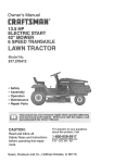
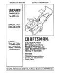
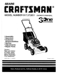
10 HORSEPOWER
32" DUAL STAGE
TRAC-PLUS
120V. ELECTRIC START
SNOW THROWER
° Assembly
+ Operation
• Maintenance
° Service and Adjustments
° Repair Parts
i i lll
iiilll
i
i
i lull
i
uumlu,_
i
lUlmu
III
,
lUllU
U.ll,i
II
im
i i,lu.m,_,,,i
SEARS, ROEBUCK AND CO., Chicago, IL 60684 U.S.A.
HHlul
u,m.
lure
HUm
I=um
=u,
,
=uHlllllu
Im
I
=umlll
=p,,,
,ll,
I I,
=l,=m,
SAFETY RULES
CAUTION:
ALWAYS
DISCONNECT
SPARK
PLUG
WIRE
AND
PLACE
WIRE
WHERE
IT CANNOT
CONTACT
SPARK
PLUG TO
PREVENT
ACCIDENTAL
STARTING
WHEN
SETTING-UP,
TRANSPORTING,
ADJUSTING
OR MAKING
REPAIRS°
A
IMPORTANT
SAFETY
STANDARDS
REQUIRE
OPERATOR
PRESENCE
CONTROLS
TO MINIMIZE
THE
RISK IDF INJURY.
YOUR SNOW THROWER
IS EQUIPPED
WITH SUCH CONTROLS.
DO _OT
ATTEMPT
TO DEFEAT
THE FUNCTION
OF THE OPERATOR
PRESENCE
CONTROL
UNDER
ANY CIRCUMSTANCES.
t,
BEFORE USE
FUEL SAFETY
•
®
Handle
o
Use an approved
•
Check fuel supply before each use, allowing
space for expansion as the heat of the engine
and/or sun can cause fuel to expand.
®
Fill fueltank outdoors
fill fuel tank indoors°
•
Replace fuel tank cap securely
spilled fuel.
o
Never remove fuel tank cap or add fuel to a
running engine or hot engine.
Never store fuel or snowthrower
with fuel in the
Read the Owner's Manual carefully. Be thoroughly famifiar with the controls and the proper
use of the snow thrower. Know how to stop the
s_ow thrower
qHickly.
®
o
and
disengage
the
controls
Do not operate the snow thrower without wearing adequate winter outer garments. Wear
footwear that will improve footing on slippery
surfaces.
Keep the area of operation clear of al! persons,
p_rficulady small children, and pets.
®
=
Thoroughly inspect the area where the snow
thrower is to be used and remove all doormats,
sleds, boards, wires, and other foreign objects.
•
Use extension
OPERATING SAFETY
cords and receptacles
fie d by the manufacturer
w_th electric
m0torsr
•
®
®
drive
as speci -.
for all snow throwers
motors
or electric
never run.
Tl'iis snow
driveways,
thrower is for use on sidewalks,
and other ground level surfaces.
garages
porches
or other such structures
or
b_.ildings,
®
Cl_eck shear bolts and other bolts at frequent
intervals for proper tightness to be sure the
snow thrower is in safe working condition.
Disengage
all clutches and shift into neutral
be_fore starting the engine.
®
Adjust the snow thrower height to clear gravel
ori'.crushed rock surface.
•
Let engine and snow thrower
temperatures
before starting
adjust to outdoor
to ctear snow.,
with extreme
care. Never
and wipe up
fumes
may
®
Never allow children or young teenagers
to
operate the snow thrower and keep them away
while it is operating.
Never allow adults to
operate the snow thrower without proper instruction_ Do not carry passengers.
=
Always wear safety glasses or eye shields
during operation orwhile performing an adjustment or repair to protect eyes from foreign
objects that may be thrown from the snow
thrower.
®
Exercise extreme caution when operating on
or crossing gravel drives, walks, or roads. Stay
alert for hidden hazards or traffic.
o
Do not put hands or feet near or under rotating
parts. Keep clear of the discharge opening at
all times°
®
Exercise caution to avoid slipping or falling, especially when operating in reverse.
•
Do not clear snow across
Use only attachments
and accessories
approved by the manufacturer of the snow thrower
(such as tire chains, electric start kits, etc.)
Never operate the snow thrower without good
visibility or light. Always be sure of your footing,
and, keep a firm hold on the handles. Walk;
fuel container.
tank inside of a building where
reach an open flame or spark.
starting
CAUTION should be exercised while using on
steep sloping surfaces. DO NOT USE SNOW
THROWER
ON
SURFACES
ABOVE
(3ROUN D LEVEL, such as roofs of residences,
o
fuel with care; it is highly flammable.
the face of slopes.
Exercise caution when changing direction on
slopes. Do not attempt to clear steep slopes.
®
Never operate the snowthrowerwithout
proper
guards, plates or other safety protective devices in place.
SAFETY RULES
•
Never operate the snow thrower near glass enclosures,
automobiles,
window wells, drop-
REPA1RtADJUSTMENTS
o
offs, and the like without proper adjustment
of
the snow discharge angle. Keep children and
pets away.
®
•
Never direct discharge at bystanders
anyone in front of the snow thrower.
®
Do not run the engine ihdoors, except when
starting the engine and for transporting
the
snow thrower in or out of the building. Open the
outside doors; exhaust fumes are dangerous
(containing CARBON MONOXIDE,
an ODORLESS and DEADLY GAS).
o
•
or allow
Take a!l possible precautions when leaving the
snow thrower
unattended°
Disengage
the
augedimpelter,
shift to neutral, stop engine,
and remove key.
Do not overload the machine capacity by attempting to clear snow at too fast a rate.
SAFE STORAGE
Always refer to Owner's Manual instructions
for important details if the snow thrower is to be
e
stored for an extended period_
Disengage power to the auger/impeller
when
snow thrower is transported
or not in use°
•
Never store the snow thrower
the snow thrower
for any dam-
age, and repair the damage before
and operating the snow thrower.
restarting
If the snow
to vibrate
thrower
should
start
abnormally, stop the engine (motor) and check
immediately
for the cause. VibratiOn is generally a warning of trouble°
•
Stop the engine (motor) whenever you leave
the operating position, before unc!ogging the
auger/impeller
housing or discharge
guide,
and when making any repairs, adjustments,
or
inspections.
o
When cleaning, repairing, or inspecting, make
certain the auger/impeller
and all moving parts
have stopped. Disconnect the spark plug wire
and keep the wire away from the plug to
prevent accidental starting_
e
Never attempt to make any adjustments while
the engine is run ning (except when specifically
recommended
by manufacturer).
•
Maintain
or replace
labels, as necessary.
•
Run the snow
thrower
throwing
snow
auger/impeller.
to prevent
®
=
After striking a foreign object, stop the engine
(motor), remove the wire from the spark plug,
disconnect
the cord on electric motors, thoroughly inspect
Never operate the snow thrower at high transport speeds on slippery surfaces. Look behind
and use care when backing.
SAFETY
with fuel in the
fuel tank inside a building where ignition sources
are present such as hot water and space
heaters, clothes dryers, and the like. Allow the
engine to cool before storing in any enclosure.
LOOK FOR THIS SYMBOL TO POINT OUT
IMPORTANT
SAFETY PRECAUTIONS.
IT
MEANS--ATTENTION!!!
BECOME ALERT!!!
YOUR SAFETY IS INVOLVED.
i , nl,i
3
n
safety
and
a few
instruction
minutes
freeze-up
after
of the
PRODUCT
CONGRATULATIONS
on your purchase of a Sears
Craftsman Snow Thrower. It has been designed, engineered and manufactured to give you the best possible
dependability and performance.
Should you experience any problem you cannot easily
remedy, please contact your nearest Sears Service CenterlDepartment. We have competent, wel!-trained technicians and the proper tools to service or repair this unit.
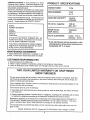
HORSE
SPECIFICATIONS
POWER:
iiiii i i
iii iiiiiiiii
t0 hp
iii i ii
11111111111
DISPLACEMENT:
21.82
cu_ in.
.....
Please read and retain this manual. The instructions will
enable you to assemble and maintain your snow thrower
properly. Always observe the "SAFETY RULES/'
,,,,,,
Ji,ill,ii IIII ii
GASOLINE
CAPACITY:
i
MODEL
imlHil,l,ii i
I
i,,lll,lu,*_
4 quarts
Unleaded
HHHHHHHHHHHill
H
OIL (26 oz. Capacity):
....
10W-30
(5W - 30) ;_`
SPARK
Champion
JSC
NUMBER 536°885020
SE_!AL
NUMBER
DATE OF
PURCHASE
PLUG :
GAP .030 in.)
VALVE
THE MODEL AND SERIAL NUMBERS WILL BE
FOUND ON A DECAL ATTACHED TO THE REAR
OF_THE SNOW THROWER HOUSING
* S.A.E. 5W-30 motor oil may be used to make
YOU SHOULD RECORD BOTH SERIAL NUMBER
starting easier in areas where tem perature
consistently
20 ° F. or lower.
ANp DATE OF PURCHASE AND KEEP IN A SAFE
PLACE FOR FUTURE REFERENCE,,
MArNTENANCE
Intake:
.010 In.
Exhaust:
.010 In.
CLEARANCE:
AGREEMENT
A Sears Maintenance Agreement is available on this
produ_cto Contact your nearest Sears Store for details,
CUSTOMER
RESPONSIBiLITiES
® Read and observe the safety rules,
® Follow a regular schedule in maintaining, caring for and using your snow thrower°
® Follow the instructions under "Maintenance" and "Storage" sections of this owner's manual.
,
,
i,,,,,,,,
i
IHIH'IIH
'1
""'"'1111
I II II
,llHIl,IHIll
H
HHHHI
TWO YEAR LIMITED WARRANTY ON CRAFTSMAN
SNOW THROWER
_or two years from the date of purchase, when this Craftsman Snow Thrower is maintained, lubricated
_nd tuned-up according to the instructions in the owner's manual Sears wilt repair, free of charge, any
defect in material and workmanship
'1
If,this Craftsman Snow Thrower is used for commercfal or rental purposes, this warranty applies for only
_0 days from the date ot purchase°
This warranty does not cover the following:
Expendable items which become worn during normal use, such as spark plugs, tire chains, drive belts
_, and shear pins_
_ Repairs necessary because of operator abuse or negligence, including bent crankshafts and the failure
to maintain the equipment according to the instructions contained in the owner's manual.
WARRANTY SERVICE IS AVAILABLE BY RETURNING THE CRAFTSMAN SNOW THROWER TO
THE NEAREST SEARS SERVICE CENTER/DEPARTMENT
IN THE UNITED STATES
THIS WAR _
RANTY APPLIES ONLY WHILE THiS PRODUCT IS IN LISE IN THE UNITED STATES°
T.his warranty gives you specific legal rights, and you may also have other rights which may vary from
state to state,
!
SEARS, ROEBUCK AND CO Department 73lCR-W
.....................................
i,l,,
i
i
Sears Tower, Chicago, 1L 60684
is
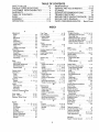
TABLE OF CONTENTS
SAFETY RULES ....................................................
2,3
PRODUCT SPECIFICATIONS
....................... 4
CUSTOMER
RESPONSIBILITIES
................ 4
WARRANTY ............................................................ 4
TABLE OF CONTENTS
.................................... 5
INDEX .................................................................
5
ASSEMBLY ...................................................... 6-10
OPERATION
................................................ 11-16
MAINTENANCE
................................................
17,18
SERVICE AND ADJUSTMENTS
............. 19-25
STORAGE ............................................................ 26
SERVICE RECOMMENDATIONS
...................27
TROUBLE SHOOTING ................................. 28
REPAIR PARTS (SNOW THROWER).,o. 30-38
REPAIR PARTS (ENGINE) ....................... 39-42
PARTS ORDERING/SERVICE
...... Back Cover
INDEX
A
Adjustment:
Auger ..........................................................
20
Belt ...........................................................
20
Beft Guide ..............................................
22
Cable ...........................................................
20
Carburetor ......................................... 25
Friction Wheel ........................................
22
Spark Plug ....................................... 25
Track ........................................................
24
Traction and Auger ....................
20
Assembly:
Crank Assembly .....................................
8
Headlight ..................................................
9
Shifter Lever ..................................9, 19
Skid Height Adjustment ................ 19
Unpacking ............................................. 7
B
Belts:
Adjust Belts .............................................
20
Belt Guide Adjustment ........................
22
Belt Maintenance ........................... 17
Replace Belts ..................................
21,22
C
Cables,Clutch ............................. 7, 9, 12
Carburetor: ......................................25, 26
Chain ............................................
t7
Choke ............................ 11, ! 2, 14, 15
OIL.itch, Levers ..............................11, 12
Controls:
Engine ................................... 11, t2, 14
Snow Thrower ..............................
11
Crank:
Adjusting Rod .............................
1g
Assembly .......................................... 8
Operation .....................................
12
Customer Responsibilities .............. 4
D
Drive, Auger ..............................
12, 2t
Drive, Traction ........................... 12, 20
Deflector, Snow Chute ................ 1l, 12
E
Engine:
Control .................................
11, 12, 14,
Oil Cap .................................... 4, 13,
Oil Change ........................................
Oil Level ....................................... 13,
Oil Type ................................... 4, 13,
Speed Governor ...........................
Starting, Electrically ......................
Starting, Manually .........................
Storage ......................................
15
18
18
18
18
26
14
15
26
F
Fuel, Type .........................................4, 13
Fuel, Storage ............................... 13, 26
Friction Wheel:
Adjustment ..............................................
22
Replacement ..................................... 23
G
Gears:
Auger Gear Box .......................... 17-18
Hex Shaft ........................................... 17
H
Handle, Upper and Lower ......................7
Headlight ...........................................9, 11
Height Adjust Skids ........................ 7, 19
Hex Shaft ............................................. 17
I
Ignition, Key ..................... 11, 12, t4, 15
Index ....................................................... 5
L
Levers:
Auger Drive Clutch ...........
7, 11, 12, 20
Choke .......................... 11, 12, 14, 15
Shifter ................................................
10-12
Throttle Control ............ 11, 12, 14, 15
Traction Drive Clutch .......7, 11, 12, 20
Lubrication:
Auger Gear Box .............................
17, 18
Auger Shaft ...................................17, 27
Chain and Sprockets .................17, 27
Engine ......................................4, 13, 18
Hex Shaft and Gears .................... 17
Weight Transfer System o. 13, 17, 18
M
Maintenance:
Agreement .....................................
4
Auger Gear Box ..........................17, 18
Auger Shaft ..........................................17
Chain and sprockets ...........................
17
Engine ............................................. 18
General Recommendations ............ 17
Hex Shaft and Gears ..................... 17
Weight Transfer System .......... !3, 19
O
Oil:
Engine ................................. 4, 13, 18
Extreme Cold Weather ............ 14, t5
Storage .................................. 13, 26
Type ...................................
4, 13, 18
5
Operation:
Engine Controls ............ 11, t2, 14, 15
Operating Snow Thrower ......... 11-16
Operating Tips ................................ 16
Starting the Engine, Electric .......... 14
Starting the Engine, Recoil ......... 15
Snow Thrower Controls ......11, 12, 13
Weight Transfer System .....! 3, 17, 19
P
Parts ............................................... 30-42
Primer Button ....................... 11, t4, 15
R
RepaidRepiacement
Parts ............30-42
Recoil Starter ................................... 15
Replacements:
Auger Shear Bolt .............................. 24
Belts .................................................... 20
Friction Wheel ............................. 22, 23
S
Safety Rules .........................................2, 3
Service and Adjustments:
Auger Housing Height .............. 7, 19
Auger Shear Bolt ............................. 24
Belts .............................................
20
Belt Guide ......................................... 22
Belt Replacements ................. 21,22
Cable ................................... 7, 10, 20
Carburetor .............................
25, 26
Friction Wheel ............................ 22, 23
Spark Plug ............................
25
Track ..........................................
24
Service Recommendations
........ 27
Spark Plug ..........................
18, 25
Specifications
................................
4
Speed Governor .......................
25
Starting the Engine:
Electric Start ..............................
14
Recoil Start ..............................
! 5;
Stopping the Snow Thrower ........... 12
Shipping Carton .........................
6, 7
Skid Height ...............................
7, 19
Shifter Lever ...................
9, 1t, 12
Shear Bolts ................................... !7, 24
Storage ...........................................
26
T
Table of Contents .......................
5
Trouble Shooting Chart .................. 28
Tools for Assembly .......................
6
Traction Drive Belt ............... 20, 21,22
Track Adjustment .................. 6, 17, 24
W
Warranty ..........................................
4
Weight Transfer System ....... 13. 17, 19
THIS SNOW THROWER IS EQUIPPED WITH "TRAC-PLUS" AND ONLY
MOVES EFFECTIVELY WHEN ENGINE IS RUNNING
If your snow thrower must be moved without the aid o! the engine, it will be easier to pull the snow thrower bankward by the handles, rather than pushing°
On start up, the track drive system may be tight and will loosen up as the snow thrower is used.. After first use,
check the track for tension and adjust if necessary, See the Track Adjustment paragraph in the Service and Adjust" ment_ section of this manual.. Check track adjustment and fasteners regularly.
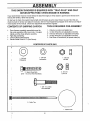
CONTENTS
OF SHIPPING
CARTON
TOOLS
12 22 t -
1 - Snow thrower completely assembled except for
tlfe_crank assembly, shifter lever knob, the upper
h_ndte, and the chute deflector assembly.
1 - P_rts Bag Containing:
t - C)wner's Manual (Not Shown)
1 - Etectdc Starter Corc195 Fto (Not Shown)
REQUIRED
FOR ASSEMBLY
Knife (to cut carton and plastic ties)
1/2 inch Wrenches (or adjustable wrenches)
9/16 inch Wrenches (or adjustable wrenches)
3/4 inch Wrenches (or adjustable wrenches)
Pair Pliers or Screwdriver (to spread cotter pin)
I
CONTENTS
i,=l==,=,rlr=,,=
=
== = H
=l
i=l= =
OF PARTS
,H,INH
BAG
imlr=m,riH,
.,H==
i
G
1 - 3/8 Inch
Lockwasher
1 - 3/8 Inch
Flatwasher
1 - 3/8 Inch
Hex Nut
! l l,l,lal l lJl l,l!
i 1)
2 - 5/16-t8
Locknuts
2 - Spare Shear Bolts
(5/16 - I8 x 2 Inch Hex Head Bolts)
)
1 - 318- 16 x 2 Inch
Hex Head Bolt
.I
"1
2 ° Cable Ties
1 -Plastic Knob
HI=IIIll
=l,=ll===,,
,,i,,i,l=lll
6
ii
ii,
i
ill
ii,lll
,
illlll,lll
ASS
iiilll
i
ill
...............................................
LY
illll,i
iHi
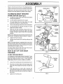
Figure I shows the snow thrower in the shipping position
LOWER HANDLE
Figure 2 shows the snow thrower completely assembled
Reference to the right and left hand side of the snow
thrower is from the operator's position at the handte_
TO REMOVE
i,,i
CONTROL
PANEL
CRANK
ASSEMBLY
CLUTCH
CABLE
SNOW THROWER
FROM CARTON
i
ii
(See Fig 1)
e
Cut all four corners q_the carton fr0omtop to bottom
and lay the panels flat..
•
Cut the cable ties attached to the augers..
e
Cut and discard the ties that secure the crank
UPPER
HANDLE
ASSEMBLY
assembly and place the assembly aside
•
Remove the packing materialfromthe
controlpaneL
=
Cut and discard the packing securing the clutch
cables to the lower handle1
®
With two 9/16 inch wrenches, loosen (do not remove) both bolts securing the upper and lower
handles Swing the upper handle into the operating
position.
NOTE: if the cables have become disconnected from the
clutch levers, reinstall the cables as shown in Figure 3.
e
Tighten both bolts securely.
e
Roll the snow thrower of{ the skid by pulling on the
handle.
NOTE: This snow thrower is equipped with a track drive
and can be hard to push when the engine is not running.
it is easier to pull the snow thrower backward if it must be
moved without the engine running
The drive system may be tight when you first use your
snow thrower. It loosens up as you use it.
HOW TO SET UP YOUR SNOW
THROWER
TO SET THE SKID HEIGHT
For shipping, the height adjust skids are reversed To use
your snow thrower, you need to remove the height adjust
skids and reinstall as shown in Fig. 2 Then adjust the
height adjust skids for surface conditions as follows:
TRACTION
DRIVE
LEVER
"Z" FITTING
Q
Loosen the mounting nuts on the skids (See Fig. 2).
O
Place the extra shear bolts (in the parts bag) under
each end of the scraper bar near but not under the
skids.
•
Push each skid up or down until it touches the
ground and the scraper bar is resting on each shear
bolt. Be sure the skids are set at the same height on
both sides
•
Tighten the mounting nuts
LY
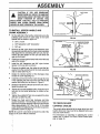
CAUTION:
tF YOU
ARE
REMOVING
RIGHT
SNOW FROM ANY ROCKY OR UNEVEN
SURFACES, RAISE THE FRONT OF THE
SNOW THROWER
BY MOVING THE
SKIDS DOWN. THIS WILL HELP TO PREVENT
ROCKS AND OTHER DEBRIS FROM BEING
HANDLE
3/8 |NCH FLATWASHER
PI_.KED UP AND THROWN BY THE AUGER.
................... H
TO iNSTALL UPPER
CRANK ASSEMBLY
I
,,lNI
HANDLE
I
AND
3/8 X 2 INCH BOLT
®
0n the right side of the handle, install and secure the
_ollowing parts (found in parts bag) in the lower
l_andle hole as shown in figure 4A:
_1- 3/8" x 2" bolt
,1 - 3/8" flatwasher & 3/8" Iockwasher
f
;1 - 3/8" nut
®
o
o
®
Remove the 3/8" nylon iocknut and flatwasher from
hneeye bolt assembly (on the chute crank assembly)
d adjust the two remaining 3/8" jam nuts, the flatwasher and the adapter on the eye bolt about half
vyay up the thread._
Install eye bolt through the lower hole on the left hand
side of the handle,
Install the 3/8" flatwasher and 3/8" nylon Iocknut
!posely on the eye bolt, as shown.
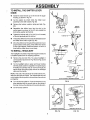
Remove the plastic cap, the cotter pin and the flatwasher from the wormed end of the crank assembly
and set aside (See Fig.. 5)..
®
Rotate the notched section of the discharge chute
toward the crank-adjusting rod.
®
Install the wormed end of the crank through the hole
in the adjusting rod and secure the end with the flat
washer and cotter pin, as shown in Figure 5.
e
Bend the ends of the cotter pin around the rod and rei0sta!l the plastic cap.
®
Tighten the eye bolt installed earlier. Keep the eye in
lipe with the rod while tightening the inside nut seo_Jrelyo
Tighten the outside 3/8" jam nut up against the other
3/8" jam nut (See Fig. 4B).
•
o
EYE BOLT
l_otate the chute crank fully clockwise and fully
€,ounter-clockwise. The discharge chute should roLatefully to the outer diamet e r of the worm and should
clear approximately 1/8" (See Fig 5).. If the chute
crank needs to be adjusted, go to the Service and Adjustments section on page 18..
NOTE: Be sure the crank does not touch the side of the
engir]e or the cover will be scratched..
FIG. 5
TO CHECK/ADJUST
CONTROL
CABLES
The control cables attached to the auger drive lever and
traction drive lever may need to be adjusted before you
use your snow thrower.
For instructions on checking or adjusting the control
cables, see To Adjust The Clutch Control Cables paragrah on page 19.
J ,,,,, i
_ ,,,,,,,,
1,1,,,
.....................................
•
,,I,H,
....
,,,
=1,=,,=,
ASSEMBLY
ii
,,1,,
TO INSTALL THE SHIFTER LEVER
KNOB
•
Stand the snow thrower up on the front of the auger
housing, as shown in Fig 6A,
•
Cut the plastic tie which holds the shifter lever
assembly to the shift bracket (Fig 6B).
•
Remove the Iocknut, washer, spring and bolt (Fig.
6D) ....
•
Reposition the shifter lever into the slot in the
control panel, as shown in Fig 6C and reinstall the
bolt, spring, washer and tocknut.
•
Tighten the Iocknut until t/8" to 3/16" (2 or 3 threads)
of the bolt protrude past the locknut.
•
Thread the shifter lever knob onto the threaded endof
,,,
,,,
,
,H,,,,,,,
H,,,
,,,,,
,
=,,,i
,
,, ,,...............................................
N,,,,,
H,
=1=,,,
,,
,,,,,,,,,!,
i,,,,,
i i ,,,,,,,,,,,
SHIFTER
BRACKET
the shifter lever until it is tight (Fig 6D)
O
Movethe shifter lever through allthe speedsto ensure
proper tension of the spring,, If the shifter lever sticks
in any of the notches, loosen the Iocknut 1/4 turn at a
time until the shifter lever moves freely.
TO INSTALL HEADLIGHT
The headlight is mounted on right side of upper handle and
is installed upside down for shipping purposes
@
Remove the pivot bolt (Fig., 7A), ptace headlight in
correct position (as shown in Fig. 7B and in Fig 2) and
retighten nut.
•
Tie the headlight cable to upper and lower handles
with the plastic cable ties supplied in the parts bag by
threading the pointed ends ot each tie through the
square ends and pulling tightly around the headlight
cable and the handle.,
LOCKNUT
NOTE: One side of the plastic tie has small notches in it,
while the other side is smooth The notched side must be
on the inside of the loop which is formed when the ends are
put together
WASHI
1/8 TO 3/16 INCH OF EXPOSED
FIG, 6
@ Tryto _oosen the cable tie If it can be loosened, it has
been attached with the smooth side on the inside of
the loop, Remove the cabletie and reverse its direction
O
THREADS
Cut off excess cable tie,
FIG. 7A
FIG. 7B
ASSEMBLY
i i
iiiii
lUU i iiiillU, UUl
i i
ii ii iiill
TO iNSTALL CHUTE ASSEMBLY TO
CHUTE FLANGE
Q
Remove the chute assembly from the carton
•
_Using a 1/2 inch wrench or adjustable wrench, remove the three (3) nuts, Iockwashers, flatwashers
and carriage bolts from the chute flange°
®
PPlacethe chute assembly over the outside of the
_chute flange so that the "A" on the chute assembly
is next to the "A" on the chute flange This will al+gn
' al!three holes correctly+
•
CHUTE
ASSEMBLY
NUT
LOCKWASHER
FLATWASHER
CARRIAGE
BOLT
(SHOWN
_.Fromthe inside of the chute flange, insert the three
[(3) carriage bolts (removed earlier) through the
SQUARE
HOLE IN
CHUTE FLANGE
\
ithree square holes The square part of the carnage
bolls should fit into the square holes in the chute
+!lange+
®
CHUTt
A
FIG. 8
.lnstall the three (3) flatwashers, !ockwashers and
'nuts (removed earlier) on the carriage bolts.
t
: ._
,Juu.ltl
CAUTION: IF ALL THE THREE (3) CARRIAGE
'_
BOLTS
CANNOT
BECORRECTLY.CHECK
MOUNTED, THE HOLES
ARE NOT
ALIGNED
THE
POSITION OF THE LETTER "A's" ON THE
CH_JTEASSEMBLY AND CHU_ FLANGE. THEY MUST
BE NEXT TO EACH OTHER+IF LESS THAN THREE (3)
HOLES LINE UP,YOU HAVE MOUNTED THE CHUTE ASSEMBLY INCORRECTt.Y AND SNOW COULD BE DISCHARGED TOWARD THE OPERATOR.RE+INSTALLTHE
CHUTE ASSEMBLY IF NECESSARY.
t
<
10
,,,,,
,
=,=,,,,
,= , H,,=,
H, i,=
,=,
=,,,,,,,,,
, ,,,
=J,,,,,,,,,,,,,,,,,,, ,
OPERATION
= =,,,,,,,,ll
,,=
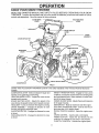
KNOW YOUR SNOW THROWER
READ THIS OWNER'S MANUAL AND SAFETY RULES BEFORE OPERATING
YOUR SNOW
THROWER.
Compare the illustrations with your snow thrower to familiarize yourself with the location of various
controls and adjustments
Save this manual for future reference,
AUGER DRIVE
LEVER
TRACTION DRIVE
LEVER
LEVER
CHUTE DEFLECTOR
WE_HT
PRIMER BUTTON
DISCHARGE
CHUTE
ELECTRIC
BUTTON
IGNITION
KEY
RECOIL
STARTER
HANDLE
CHOKECONTROL
THRO'I'TLE CONTROL
SCRAPER
BAR
FIG. 9
,,,,,,
,,,,,
,,,,
, ,,,,
uu,,
SEARS TRAC-PLUS SNOW THROWERS
Institute.
u ,,
,,,,,,,,,,,,,,,,,
,,,, .............................................
conform to the safety standards of the American National Standards
AuG E'R......................................
DRIVE LEVER - Starts and stops the auger
=,=
and
=
,===
=,,=lLIJ
WEIGHT TRANSFER PEDAL- Engage for heavy snow
conditions, to keep the snow thrower from climbing drifts
and hard-packed snow When released, it eases transport of the snow thrower.
HEIGHT ADJUST SKIDS - Adjusts the ground clearance
of the auger housing.
IGNITION KEY - Must be inserted to start the engine.
ELECTRIC STARTER BUTTON - Used to start the engine using the 120 V electric starter.
RECOIL STARTER HANDLE - Starts the engine manually,
CHOKE CONTROL - Used to start a cold engine
PRIMER BUTTON - Injects the fuel directly into the
carburetor or mainfold for fast starts in cold weather
THROTTLE CONTROL - Controts the engine speed
impelIer (snow gathering and throwing),
TRACTION DRIVE LEVER _ Propels the snow thrower
lorward and in reverse.
SPEED SHIFTER LEVER - Selects the speed of the
snow thrower (6 speeds torward and 2 speeds reverse)
HEADLIGHT - Turns on whenever the engine is running
CRANK ASSEMBLY - Changes the direction of snow
throwing through the discharge chute.
CHUTE DEFLECTOR - Changes the distance the snow
is thrown_
DISCHARGE CHUTE - Changes the direction the snow
is thrown
!1
............,,,r,Ji
II "nil''"
"¸l ''u¸"
I
:
:
OPERAT
i
.....................
nHnnn,Hu
, ,,,,,
,,,, ,,,,,,,,,, ,,,,,,,,,,,,,,,i.,.
The operation of any snow thrower can result in foreign objects being thrown into the
eyes, which can resutt in severe eye damage. Always wear safety glasses or eye
shields while operating the snow thrower.,
We recommend standard safety glasses or wide vision safety mask tor over your
glasses available at SEARS Retail or Catalog Stores.
LUL
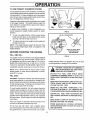
HOW TO USE YOUR SNOW
THROWER
TO _.,ONTROL
SNOW
Turn the crank assembly to set the direction of the
snow throwing.
e
_oosen the wing knob on the chute deflector and
Wove the deflector to set the distance Move the
deflector UP for more distance, DOWN for less
distance. Then tighten the wing knob (Fig. '10)
YOUR SNOW
To stop throwing snow, release lhe auger drive
"..
e
.!_ver (See Fig_ 12)_
To stop the track, release the traction ddve lever
FIG. 10
PRIMER BUTTON
ELECTRIC
STARTER
BUTTON
T_ostop the engine, push the throttle control lever to
oft and pull out the ignition key (See Fig. tl).
TO MOVE
®
\
THROWER
•
®
WING KNOB
DISCHARGE
•
TO _TOP
J±1111'1111
FORWARD
AND
IGNITION
KEY
BACKWARD
T_Oshift, release the traction drive lever and move
the speed shifter lever to the speed you desire.
Ground speed is determined by snow conditions
Select the speed you desire by moving the speed
shifter lever intot he appropriate colored area on the
cpntrol panel°
Red - Wet, Heavy, Slushy, Extra Deep
Amber-
CHOKE
CONTROL
RECOI L STARTER
HANDLE
THROTTLE
CONTROL
FIG. 11
TRACTIONDRIVE
LEVER
Moderate
AUGERDRIVE
LEVER
OFF
White - Very Light
ell
i Green - Transport only
®
Engage the traction drive lever (See Fig 12, left
5_nd). As the snow thrower starts to move, maintain
a,firm hold on the handles, and guide the snow
thrower along the clearing path Do not attempt to
push the snow thrower°
®
_o move the snow thrower backward, move the
_peed shitter lever into first or second reverse and
"e_gage the traction drive lever (left hand)
IMPORTANT:
TO THROW
LE.
i
•
Release to slop throwing snow
i
i
ill,
f
uH
i
i
ul
nil,
illl
ill
R,GHT
HAND
i
,i
illl
FIG. 12
CAUTION: READ OWNER'S MANUAL
BEFORE
OPERATING
MACHINE.
NEVER DIRECT DISCHARGE TOWARD
BYSTANDERS.
STOP THE ENGINE
BEFORE UNCLOGGING
DISCHARGE
CHUTE OR AUGER HOUSING AND
BEFORE LEAVING THE MACHINE.
SNOW
PUsh down the auger drive lever (See Fig 12,
right hand)_
i
i
\
HAND
DO NOTMOVETHESPEED
SHIFTER
LEVER WHILE THE TRACTION
LEVER IS DOWN.
e
2
H,I
12
,
,
,
i1,1
i
n,ii
i i
,ira,,
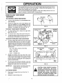
TO USE WEIGHT
TRANSFER
SYSTEM
In hard packed or heavy snow conditions, conventional
snow throwers tend to ride up and leave uneven mounds
of snow behind, For these conditions, your new tracked
snow thrower has a unique weight transfer system (See
Fig 13) designed to minimize ride-upr
OFF
Stepping on the weight transfer pedal shifts more weight
to the auger housing,, This weight transfer keeps the
snow thrower in contact with the ground and reduces
ride-up on ice and snow1
ON
In lighter snow conditions or when transporting, you
should release the weight transfer system for easier
steering,
•
FIG,13
OIL FILL CAPtDIPSTICK
To use the weight transfer, hold the upper handle
firmly and push down on the weight transfer pedal
(See Fig I3) with the bali of your foot
•
To release, pull up on the weight transfer pedal with
the top of your foot,
NOTE: The weight transfer system will not work if the
auger housing height adjust skids are adjusted to the
highest position,
BEFORE
STARTING
FILL/ADD
OIL:
NOTE: OIL LEVEL MUST
BE BETWEEN FULL
AND ADD MARK
THE ENGINE
FIG.14
The engine on this snow thrower was shipped without
oil Add oil before you start the engine Remove the oil
fill capfdipstick and till the crank case to FULL line on
dipstick (26 ounces) (See Fig 14) with SAE
10 W-30
motor oil (or equivalent) Do not overfill. Tighten the fill
foreign particles, Never use gasoline that may be stale
from long periods of storage in the container,
, i,u,i
cap/dipstick securely each time you check the oil level.
H
, .............................
CAUTION: GASOLINE IS FLAMMABLE
AND CAUTION MUST BE USED WHEN
HANDLING OR STORING IT,
NOTE: S.A E 5W-30 motor oil may be used to make
starting easier in areas where temperature is consistently 20 ° F or lower
DO NOT FILL FUEL TANK WHILE SNOW
THROWER IS RUNNING,WHEN IT IS HOT, OR
WHEN SNOW THROWER IS IN AN ENCLOSED
AREA.
FILL GAS:
WARNING: Experience indicates that alcohot blended
fuels (called gasohot or using ethanol or methanol) can
attract moisture which leads to separation and formation
of acids during storage Acidic gas can damage the fuel
system of an engine while in storage
KEEP AWAY FROM OPEN FLAME OR AN ELECTRICAL SPARK AND DO NOT SMOKE WHILE
FILLING THE FUEL TANK.
NEVER FILL THE TANK COMPLETELY. FILL
TH E TAN K TO WITHIN 1/4"- 1/2" FROM THE TOP
TO PROVIDE SPACE FOR EXPANSION OF FUEL,
To avoid engine problems, the fuel system should be
emptied before storage for 30 days or longer. Start the
engine and let it run until the fuel lines and carburetor are
empty, Use the carburetor bowl drain to empty residual
gasolinefromthe
float chamber (See Fig. 42)Use fresh
fuel next season. (See Storage instructions for additional
information )
ALWAYS FILL FUEL. TANK OUTDOORS AND
USE A FUNNEL OR SPOUT TO PREVENT SPILLINGo
MAKE SURE TO WIPE UP ANY SPILLED
BEFORE STARTING THE ENGINE,
Never use engine or carburetor cleaner products in the
fuel tank or permanent damage may occur
FUEL
STORE GASOLINE IN A CLEAN, APPROVED
CONTAINER AND KEEP THE CAP IN PLACE ON
THE CONTAINER,
Fill the fuel tank with clean, fresh, unleaded grade
automotive gasoline Be sure that the container you pour
the gasoline from is clean and free from rust or other
....
13
,H
,
OPERATION
ii
illl
ill
TO STOP ENGINE
o
BUTTON
To stop engine, move the throttle control lever to
STOP position and remove key Keep th,t key in a
safe place.. The engine will not start without the key.
TO START ENGINE (Electric
Starter)
IGNITION
Be sure that the engine has sufficient oil., The snow
thrower engine is equipped with a 120 volt A C electric
starter and recoil starter. Before starting the engine, be
Certail_ tha.t you Rave read the following information:
COED START
•
BOX
CHOKE
CONTROL
(See Fig. 15)
THROTTLE
_e sure the auger drive and traction drive levers
are in the disengaged RELEASED position.
e
Move the throttle control up to FAST position.
•
Remove the keys from the plastic bag_ Insert one
_ey intothe ignition slot Be sure it snaps into place.
DO NOT TURN KEY. Keep the second key in a
s_afeplace.
®
_otate the choke knob to FULL choke position.
e
Connect the power cord to the switch box on the
e
engine..
Plug the other end ot the power cord into a three
hole, grounded 120 volt AC receptacle.
®
Press primer button in cold weather.. Press twot_ree times while keeping you r finger over the vent
I_oie on the primer button Additional priming may
be,necessary for the first start if the temperature is
below 15 ° F.
e
push down on the starter button until the engine
starts Do not crank for more than 10 seconds at a
•
FIG,15
CAUTION: THIS STARTER IS EQUIPPED
WITH A TH REE-WIRE POWER CORD AND
PLUG AND IS DESIGNED TO OPERATE
ON 120 VOLT AC HOUSEHOLD CURRENT. IT MUST BE PROPERLY GROUNDED AT
ALL TIMES TO AVOID THE POSSIBILITY OF ELECTRICAL SHOCK, WHICH MAY BE INJURIOUS TO
OPERATOR.
FOLLOW
ALL INSTRUCTIONS
CAREFULLY AS SET FORTH IN THE "TO START
ENGINE" SECTION. DETERMINE
THAT YOUR
HOUSE WIRING IS A THREE-WiRE GROUNDED
SYSTEM. ASK A LICENSED ELECTRICIAN IF YOU
ARE NOT SURE. IF YOUR HOUSE WIRE SYSTEM
IS NOT A THREE-WIRE SYSTEM, DO NOT USE
THIS ELECTRIC STARTER UNDER ANY CONDITIONS. IF YOUR SYSTEM IS GROUNDED AND A
THREE-HOLE RECEPTACLE IS NOT AVAILABLE
AT THE POINT YOUR STARTER WILL, NORMALLY
i
time. This electric starter is thermally protected. If
overheated it wel! stop automatically and can be
restarted only when it has cooled to a safe temperature (a wait of about 5 to 10 minutes is required)
e
CONTROL
BE USED, ONE SHOULD
LICENSED ELECTRICIAN.
BE INSTALLED
WHEN CONNECTING 120 VOLT AC POWER CORD,
ALWAYS CONNECT THE CORD TO THE SWITCH
BOX ON THE ENGINE FIRST, THEN PLUG THE
OTHER END INTO THE THREE-HOLE GROUNDED
RECEPTACLE.
VVhen the engine starts, release the starter button
and slowly rotate the choke to OFF position., If the
ejlgine falters, rotate the choke to FULL and then
gradually to OFF.
WHEN DISCONNECTING POWER CORD_ ALWAYS
!.UNPLUG
THE END IN THE THREE-HOLE
i
e
._isconnect the power cord from the receptacle first
._ind then from switch box on engine.
i GROUNDED RECEPTACLE
NOTE: Allow the engine to warm up for a few minutes
because the engine will not develop full power until it
reaches operating temperature.
•
Run the engine at full throttle (FAST) speed when
throwing snow,.
WARM
START
If restaTrting a warm engine after a short shutdown, leave
choke 'at OFF and do not push the primer button
:
BY A
14
FIRST.
,,
==,=
,,,,,,,,
, ,,,,, ,, ,
,,
OPERATION
=
i=
N,,,
........
=,
=,,=1,,i,
,,,
=,
CAUTION: NEVER RUN ENGINE INDOORS OR IN ENCLOSED, POORLY
VENTILATED AREAS. ENGINE EXHAUST CONTAINS CARBON MONOXIDE, AN ODORLESS AND DEADLY GAS°
KEEP HANDS, FEET, HAIR AND LOOSE
CLOTHING AWAY FROM ANY MOVING PARTS
ON ENGINE AND SNOW THROWER.
WARNING: TEMPERATURE OF MUFFLER AND
NEARBY AREAS MAY EXCEED 150 ° F. AVOID
THESE AREAS.
DO NOT ALLOW CHILDREN OR YOUNG TEENAGERS TO OPERATE OR BE NEAR SNOW
THROWER WHILE IT IS OPERATING.
IGNITION
KEY
....................
FIG.16
NOTE: Allow the engine to warm up for a few minutes
because the engine wil! not develop full power until it
reaches operating temperature.
=
Run the engine at or near the top speed when
throwing snow
FROZEN
•
Be sure the auger drive and the traction drive levers
are in the disengaged RELEASED position
•
•
Push the key into the ignition slot Be sure it snaps
into place. Do not turn key. Remove ptastic bag and
extra key.
®
Rotate choke control to FULL choke position
O
STARTER
Pull as much rope out of the starter as possible.
o
Release the starter handle and let it snap back
against the starter..
tf the engine still fails to start, repeat If continued attempts do not free starter, follow the electric cold start
procedures to start.
To help prevent possible freeze-up of recoil starter and
engine controls, proceed as fotlows after each snow
removal job.
e,
With the engine running, pull the starter rope hard
with a co ntinuous full arm stroke three or four times..
Pulling of starter rope will produce a loud clattering
sound. This is not harmful to the engine or starter
Press the primer button two or three times, while
keeping your finger over the vent hole o n the primer
button. Additional priming may be necessary for the
first start if the temperature is below 15° F
e
RECOIL
If the starter is frozen and will not turn engine:
(See Fig. 16)
Move the throttle control up to FAST position.
START
If restarting a warm engine after a short shutdown, leave
choke at OFF and do not push the primer button
Be sure that the engine has sufficient oil. Before starting
the engine, be certain that you have read the following
information:
®
STARTER
HANDLE
=,
WARM
e
,,,H
THROTTLE CONTROL
TO START ENGINE (Recoil Starter)
START
,,
\
To stop engine, move the throttle controt lever to
STOP position and remove key. Keep the key in a
safe place. The engine witl not start without the keyr
COLD
,=,,,
,,,,,,,,,H
CHOKE
CONTROL
TO STOP ENGINE
e
,,,,,,,,l,l,,,,,,
N,
=,
Pull the starter handle rapidly. Do not allow the
handle to snap back, but allow it to rewind slowly
while keeping a firm hold on the starter handle..
o
As the engine warms up and begins to operate
evenly, rotate the choke knob slowly to OFF position. If the engine falters, return to FULL choke, then
slowly move to OFF choke position
With the engine not running, wipe all snow and
moisture from the carburetor cover in area of control
levers.. Also move throttle control, choke control,
and starter handle several times and leave in off
position.. Leave choke in Full position
15
i
i
OPERATIO
SNOW THROWING
•
TIPS
CAUTION:
DO NOT ATTEMPT
TO RE-
For maximumsnowthrower
efficiency, ad_JStground
speed, not throttle, If the track slips, reduce forward
speed. The engine is designed to deliver maximum
p_dormance at full throttle and should be run at trois
power setting at all times..
® RELEASE AUGER
DRIVE LEVERS.
DRIVE
Most efficient snow throwing is accomplished when
the snow is removed immediately after it falls
e MOVE THROTTLE
TION°
LEVER TO STOP POSI-
e
_For complete sn0w removal, slightly Overlap each
•path previously taken.
e
The snow should be discharged down wind when_e_,erpossible.
•
'For normal usage, set the skids so that the scraper
_'bar is 1/8" above the skids. For extremely hardpacked snow surfaces, adjust the skids upward so
_hat the scraper bar touches the ground
®
_'Ongravel or crushed rock surfaces, set the skids at
,'I-1/4" below the scraper bar (see To Adjust Skids
_eight paragraph on page 19). Rocks and gravel
must not be picked up and thrown by the machine.
•
If the front of the snow thrower has a tendency to
.._raise,reduce the ground speed and engage the
weight transfer system.
•
_After the snow throwing job has been completed,
,allow the engine to idle for a few minutes, which will
•melt snow and accumulated ice off the engine.
®
Clean the snow thrower thoroughly after each use.
•
Remove ice and snow accumulation and all debris
!tom the entire snow thrower, and flush with water
{if possible) to remove all salt or other chemicals.
Wipe snow thrower dry.
-1
/
'16
LODGED
IN ITEM
AUGER
WITHOUT
TAKING
MOVE ANY
THAT
MAY BECOME
THE FOLLOWING PRECAUTIONS,'
AND TP.ACIION
= REMOVE (DO NOT TURN) IGNITION KEY_
• DISCONNECT
SPARK PLUG WIRE.
• DO NOT PLACE YOUR HANDS IN THE
AUGER OR DISCHARGE CHUTE. USE A
PRY BAR.
iiiii
..............
TENANCE
ii
i ,ll,l,m,
ii_J
GENERAL
, i
ii,,,
...............
, L,ILII
i
RECOMMENDATIONS
iii
iillll ,i
ill illlll
, i,, u
i, I,I,,IL,LIIL,,I,,
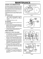
OIL(CHAINSANDSPROCKETS)
The warranty on this snow thrower does not cover items
that have been subjected to operator abuse or negligence. To receive fullvalue fromthewarranty, operator
must maintain snow thrower as instructed in this manual
Some adjustments will need to be made periodically to
properly maintain your snow thrower
A!l adjustments in the Service andAdjustments ' section
of this manual should be checked at least once each
season
AFTER
o
•
FIRST
l llll
USE
,,
,
............
FIG ,17
Check the tracks for tension and adjust if necessary
(See To Adjust Track paragraph on page 24)
Check the track adjustment
and fasteners
regularly.
WEIGHT
TRANSFER
PIVOT
Be sure that all fasteners are tight.
WEIGHT
TRANSFER
PLATE
AS REQUIRED
The following adjustments
than once each season
•
®
should be performed more
Auger and Track Drive Belts shouldbe adjusted after
the first 2 to 4 hours of use, again about mid-season
and twice each season thereafter
See To Adjust
Belts paragraph on page 20
\
FIG, 18
All screws and nuts should be checked oftento make
sure they are tight, preferably after each use
SNOW THROWER
LUBRICATION
- EVERY
TEN
HOURS
®
Chain and Sprockets- Oil chains and sprockets (See
Fig 17) with 10W-30 oil (or equivalent) after 10 hours
use and at the end of each season
e
Weight Transfer System- Coat weight transfer plate
(See Fig 18) with clinging type grease, such as
Lubriplate, every ten (10) hours and before storage.
e
Auger Shaft- Using a hand grease gun, lubricate the
auger shaft zerk fittings (See A, Fig. 19) every ten
(10) operating hours
Each time a shear bolt is
replaced (see To Replace the Auger Shear Bolt (on
page 24), the auger shaft MUST be greased
=
For storage or when replacing shear bolts, remove
shear bolts and lubricate auger shaft zerks Rotate
auger several times on shaft and reinstall shear
bolts°
LUBRICATION
- NOT REQUIRED
Hex Shaft and Gears - Hex shaft and gears require
no lubrication.
All bearings and bushings are
lubricated for lifetime and require no maintenance
(See Fig 20).
FIG.20
17
TENANCE
i iii ill
ill llll
iiii
i
, iiiiiii i,illllllM,,II
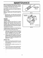
NOTE: Any greasing or oiling of the above components
can cause contamination of the friction wheet tf the disc
drive plate or friction wheel come in contact _th grease
or oil, damage to the friction wheel will result.
"_
.,_,_To,
L" ..,/._,V
.,,_"F._"."_7
Should grease or oil come in contact with the disc dd_e
plate or friction wheel, be sure to clean the plate and
wheel thoroughly.
OIL LEVEL
MUST BE B !_TWEEN
FULt
'_,',q)
AD[_ MARK
NOTE! For storage, the hex shaft and gears should be
wiped _with 10W-30 motor oil to prevent rusting (See
Fig. 19).
®
.__NOTE:
FIG. 21
Auger Gear Box - The auger gear box has been
factory lubricated for life. If for some reason lubricant
Sl_ould leak out, have auger gear case checked by a
co[npetent repairman
OIL FILLCAP/
DIPSTICK
ENGINE
LUBRICATION
Check, the crankcase
oil level (See Fig. 21) before
startin_l the engine and after each five (5) hours of
contin'uous use.
Add SAE
10W-30 motor oil or
equivale'nto Tighten fill cap/dipstick securely each time
you ch_ck the oil level° S.A.E. 5W-30 motor oil may be
used to make starting easier in areas where temperature
is consistently 20 ° F or lower..
OIL DRAIN PLUG
FtGo 22
Change the oil after first two hours of operation and every
25 hot_rs thereafter or at least once a year if the snow
thrower is not used for 25 hours (See Fig. 22).
®
Pbsition snow thrower so that the oil drain plug is
lowest point on the engine, Remove oil drain plug
and oil fill cap/dipstick
Drain oil into a suitable
"t
,
container. Oil will drain more freely when warm.
o
Reptace oil drain plug and tighten securely Refill
crankcase with SAE. 10W-30 motor oil (or equivalent).. SA E. 5W-30 motor oil may be used to make
sBrting easier in areas where temperature is consi_tently 20 ° F or towerr
SPARK
•
PLUG
Make sure that the spark ptug is tightened secu rely
i_o the engine and the spark plug wire is attached
.re the spark plug..
e
lPa torque wrench is available, torque plug to 18 to
*'h
23 foot pounds
e
Clean the area around the spark plug base before
J
.
,
r_moval to prevent d_rtfrom entering the engine
e
Clean the spark plug and reset the gap periodically
t
18
,,,
................
.
i illllllllll
,l,u
ii illlll .................
AND ADJUSTMENTS
•
i,i
•
,
I I,H,IIIll
i ii
,i,
................ i,
liHi
i
i i ill i
...........................
H,J,
illll,i
ii
,,
SKID MOUNTING
u,,,,,.,
,,,,,,
ill
i i
NUTS
SPARK PLUG WIRE AND TIE BACK
!
...................
AWAY
FROM
THE
PLUG
BEFORE
MAKCAUTION: ALWAYS DISCONNECT THE iI
ING ANY ADJUSTMENTS
TO ADJUST
OR REPAIRS.
i
SKIDS HEIGHT
This snow thrower is equipped with two height adjustment skids, located on the outside of the auger housing
(See Fig_ 23), Thes-e Skids_elevate the front of the snow
thrower
AUGER HOUSING
i,,,
H IIIHHI
HEIGHT ADJUST
I I,I
IN,HH
FIG. 23
For normal hard surfaces, adjust the skids as follows:
o
Make sure the snow thrower is on a hard, Ievel
surface and the weight transfer system lever is
released See page 13
e
Place extra shear bofts supplied (found in parts
bag) under each end of the scraper bar near but not
under the skids,,
o
Loosen the skid mounting nuts (See Fig, 23) and
push the skids down until they touch the ground,
Retighten the mounting nuts,
SKID
I,H
CAUTION: BE CERTAIN TO MAINTAIN
PROPER GROLIND CLEARANCE FOR
YOUR PARTICULAR
AREA TO BE
CLEARED,
OBJECTS
SUCH
AS
GRAVEL, ROCKS OR OTHER DEBRIS,
IF STRUCK BY THE IMPELLER_ MAY BE
THROWN WITH SUFFICIENT FORCE TO
CAUSE PERSONAL INJURY, PROPERTY
DAMAGE OR DAMAGE TO THE SNOW
THROWER..
ii.....................................................................
For rocky or uneven surfaces, raise the front of the snow
thrower by moving the skids down This will help prevent
rocks and other debris from being picked up and thrown
by the auger
TO ADJUST
NOTE: If the skids are at the maximum height, the weight
transfer system wit{ not work,
if you cannot rotate the chute crank tully to the left and lo
the right, you need to adjust the chute crank (See Fig, 24).
TO ADJUST
SCRAPER
CRANK
BAR
After considerable use, the metal scraper bar will have a
definite wear pattern The scraper bar in conjunction
with the skids should always be adjusted to allow 1/8"
between the scraper bar and the sidewalk or area to be
cleaned.
e
Position the snow thrower on a Ievel surface
•
Loosen the carriage bolts and nuts securing the
scraper bar to the auger housing.
®
Adjust the scraper bar to the proper position
•
Tightenthe carriage bolts and nuts, making surethat
the scraper bar is paralle_ with the working surface.
o
After extended operation, the scraper bar may be
reversed if the scraper bar must be replaced due
to wear, remove the carriage bolts and nuts and
install a new scraper bar.
CHUTE
ASSEMBLY
e
Loosen both 1/2" nuts on the crank adjusting rod
(using 3/4" wrenches),
®
Rotate the adjusting rod in or out to allow about 1/8"
clearance between the notch in the flange and the
outer diameter of the worm.
e
Once this clearance is set, tighten the nuts.
NOTE: Be sure the crank does not touch the side of the
engine or the cover will be scratched
................
PLASTIC
CAP
_
..•
_'
Lii,ll ,,,,
NOTCHED
SECTION
COTTER
PiN
FLATWASHER
112 INCH
CRANK ADJUSTING
ROD
WORM
FIG. 24
!9
SERVICE AN
ADJUST
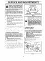
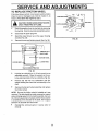
TO ADJUST THE CLUTCH CONTROL
CABLES
T$
TRACTION
DRIVE
LEVER
Periodiq adjustment of the cables may be required due to
normal stretch and wear on the belts. To check Ior correct
CONTROL LEVER
MUST BE tN FULL
FORWARD PO_{ITION _,JustCm_ =ct.
Ing F',___o BuLnper)
WHEN CHECKING
"Z" FII-rING
adjustment, the control lever must be in the full forward
position, resting on the plastic bumper. The control
cables are correctly adjusted when the center of the "Z"
fiUing istin the center of the hole and there is no droop in
the cable (See Fig. 25) ........
PLASTICBUMPER
If adjustment is necessary:
•
Push the cable through the spring (See Fig 26) to
expose the threaded portion of the cable
•
Hold the square end of the threaded portion with
pliers and adjust the Iocknut in or out until the excess
slack is removed.
e
Pull the cable back through the spring and connect
the _able..
FIG. 25
e" Do'the same for the other lever cable
NOTE:-Whenever the traction drive or auger belts are
adjusted or replaced, the cables will need to be adjusted.
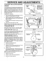
TO ADJUST
BELTS
Belts str_etch during normal use. If you need to adjust
the belt,_ due to wear or stretch, proceed as follows:
TRACK
DRIVE
BELT (See Fig. 28)
The track drive belt has constant spring pressure and
does not require adjustment. Check the clutch control
cable adjustment before replacing the belt
Replace_ the track ddve belt if it is still slipping (see To
Replace' Bells paragraph on page 22)°
AUGER
DRIVE
1t2 iNCH
DEFLECTION
ENGAGED
BELT (see Fig. 28)
If your snow thrower will not discharge snow, check the
control cable adjustment. If it is correct then check the
condition of the auger drive belt. It may be loose or
damaged. If it is damaged, replace it See To Replace
Belts p_agraph on page 21. If the auger drive belt is
loose, a_just as follows:
®
Disconnect the spark plugwire.
®
Ren_ove the belt cover_
®
Lo0_en the nut on the idler pulley (See Fig. 27) and
PULLEY
FIG, 27
_,
TRACTION
DRIVE BELT
ENGINE
PULLEY
mo_e the pulley toward the belt about t/8'L
®
TRACTION
Tighten the nuL
Press the augerdrive lever_ Checkthetension onthe
belt {(opposite idler pulley). The belt should deflect
abo0t i/2" with moderate pressure (See Fig. 27).
NOTE: You may have to move the idler pulley more than
_'_,
o
AUGER IDLER
PULLEY
once to obtain the correct tension
® Reptacethe belt cover.
•
Che_k the clutch control cable adjustment.
®
Rec6nnectthe
AUGER DRIVE BELT
ii
FIG°28
spark plug wire
2O
fr IIH,
I ,,',,
Ill
Ill,
II,
I
II
I,I
I'
II
III I
II
II,I
II,,
I
I
II,I,
I ,llll
,,
'
I,,I,
IlL
•
............
SERVIC ............
AN
.... ADJUSTIVlENTS
........................
TO REPLACE
i .N,,,
BELTS
H .i ,,L
I
The drive belts on this snow thrower are of special
construction
and should be replaced with original
equipment belts available from your nearest SEARS
Store or Service Center,
You will need the assistance of a second person white
replacing the belts,.
e__
BELTCOVER
1/4 X 1/2 INCH SELF
TAPPING SCREW
Drain the gasoline from the fue! tank by removing the fuel
line.i Drain the gas and reinstall fuel line.
% TOP BOLT
BOTTOM NUT
.................................
CAUTION:
i _lll
•
AUGER
DRAIN THE GASOLINE OUT
DOORSill ' AWAY,FROM
ill
DRIVE
FIRE i OR
FLAME
.,.
,i
I
"i
i
-LLI_
BELT
i
If your snow thrower will not discharge snow, and the
auger drive belt is damaged, replace it as foltows:
•
Disconnect the spark plug wire_
o
Remove the belt cover (See Fig, 29)
®
Remove the auger drive engine putley, Removing
the engine pulley allows you to remove the belt
without removing the belt guides (See Fig. 30)
•
Remove plastic cap, cotter pin and washer from the
wormed end of crank assembly (See Fig 24)
o
Remove crank assembly from adjusting rod and
slide crank out of the way
®
illll i
...........................
TRACTION....
DRIVE
BELT
,_
TRACTION -,i-_
IDLERPULLEY
)'
_ TRACTIONDRIVEBELT
TRACKDRIVE
PULLEY
BELTGUIDE
AUGER
PULLEY
BRAKE ASSEMBLY
Have someone hold up on the upper handles
ill.i
Remove the top two bolts (See Fig. 29) holding the
auger housing to the motor mount frame
e
ill
FIG, 29
ii
i lll
.i
i,ill
FIG. 30
.
ii
ii
i,,,,i
i,
The auger housing and motor frame will separate
(pivoting on lower bolts)
NOTE: It may be necessary to slightly loosen the bottom
nuts (See Fig. 29) to get the auger housing and motor
mount to pivot,
e
Bend tthe belt retainer tabs (See Fig 3t ) away from
the auger pulley.
•
Remove the old auger belt and install new one,.
®
Pull up on the belt to hold it firmly in the "V" of the
pulley and bend the belt retainers back into position
leaving t/16 to 1/8 inch clearance between the bett
and the belt retainer tabs,
AUGER
"_PULLEY
/
1/16 TO 118 INCH
CLEARANCE
WITHBELT
FIRMLY IN "V'"
BELT
O
RETAINER
TABS
e
Standing on the right side of the snow thrower, puit
up the auger drive belt
•
Have someone engage the auger drive lever and
pivot the motor mount frame back into position
=
NOTE: Engaging the auger dr ve lever moves the auger
brake out of the way.
Adjust drive belt, see To Adjust Belts paragraph on
page 20
e
Reinstall the removed parts in reverse order of
removal,
•
Reinstall the top two bolts that hold the auger
housing to the motor mount frame and tighten the
bottom two nuts if they were loosened
e
Place the auger drive belt on the engine pulley and
reinstall the auger drive engine pulley
FIG. 31
21
uiL i,i
SERVICE AND ADJUST
TRACK
DRIVE BELT
.................
iiii
If your snow thrower will not move forward check the
track drive belt tot wear. If the track drive belt needs to
be repl,_ced, proceed as follows:
=
_isconnect the spark plug wire
•
Remove the belt cover,,
•
Fqllow steps 4 through 9 of the Auger Drive Belt
Replacement paragraph on page 21.
o
P_II the spring loaded tract on drive idler pulley (See
Fig. 30) away from the traction drive belt,
•
TS
i
REMOVE BOLT _"
[--
T
REAR PANEL
BOSOM
PANEL
LOOSENBO_
LOOSEN BOLl"
TRACKCONNECTINGROD
R#move the traction drive belt from the engine
pulley,
FIG. 32
NOTE:you may have to move the auger brake assembly
(See Fig 30) to remove the belt from the traction drive
pulley,
•
In_;tall the replacement belt and reinstall the removed parts _n reverse order of removal
.J
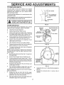
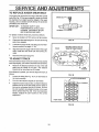
TO AE_JUST THE FRICTION
WHEEL
If tl_e snow thrower will not move forward, you need to
check the track drive belt, the traction drive cable or the
friction Wheel, If the friction wheel is damaged, it will need
to be replaced See the To Replace Friction Wheel
paragratoh on page 23, If the friction wheel is not worn,
check th e adjustment, as follows:
o
DisCOnnect spark plug wire,
•
FRICTIONWHEEL
DISCDRIVEPLATE
2-5t8 INCH
FIG. 33
Drain the gasoline from the gas tank.
•
Sta!_d snow thrower on end,
®
Remove the bottom panel (See Fig, 32)
e
Position the shifter lever in first (1) gear
®
Note ihe position of the friction wheel on the disc
drive t?late The right side of the friction wheel should
be 2-5/8" fro m the left outer side of the disc drive plate
(See Fig. 33).
,r,rll ii Illllll' In
lull
I
I
SPEED
SELECT
ROD
A
ADAPTOR
SHIFTER
If adjustment is necessary:
®
BALLJOINT
Loosen the jam nut "A" on the speed select rod
Rer_ove the ball joint from the shifter bracket
_,.
LEVER
Lengthen or shorten the rod by turning the adaptor to
obtain the correct friction wheel position (See Fig,
34),i
•
Re'i_stall the ball joint and tighten lhe jam nut.
o
Reir_statl the botlom panel,
FIG. 34
22
l
SERVICE AND ADJUSTMENTS
,
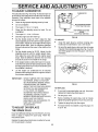
TO REPLACE
nnn,
l,,Hl,,,,,,,,,,,,,,l,,,
,,,,, ,,,,
FRICTION
n,
,,l,,,iHullJ,,,it,
WHEEL
Ifthesnowthrowerwitl not move forward, andthefriction
wheel is worn or damaged, you need to replace it, as
follows: (First allow the engine to cooL)
FRICTION
WHEEL
HEX SHAFT
_lb
CLUTCH ASSEMBLY
AWAY
FROM
FIREGASOLINE
OR FLAME°
CAUTION:
DRAIN
OUTDOORS I
3!8"NUT
•
Di'ain the gasoline from the fuel tai_k 6y removing
the fuel tineo Drain the fuel and reinstall the fuel line,
•
Disconnect the spark plug wire.
e
Stand the snow thrower up on the auger housing
end (See Fig, 35),,
o
Remove the rear and bottom panels (See Fig 35),
i,i
,1,,
;:{EMOVE BOL_
FIG. 36
i i l!,n
:_'
I_
REMOVE BOLT
REAR PANEL
Ill
LOOSEN BOLT--
_
I ti
._._
BOTTOM PANEL
LOOSEN BOLT
TRACK CONNECTING
ROD
FIG. 35
®
Hold the hex shaft with an 11/16 inch wrench (or an
adjustable wrench) Place the wrench on the extreme right hand side of the hex shaft (See Fig 36)
•
Remove the 3/8 inch nut, tockwasher and flatwasher holding the wheel and hub assembly to the
shaft
e
Remove the hub and wheel assembly and replace
the friction wheel,
NOTE: Be sure the friction wheel is installed as it was
removed The hub should be inside recessed or cupped
end and facing away from the clutch assembly Be sure
the 1/8 inch square key is in place and the thrust washer
is completely on the shoulder of the shaft, NOT trapped
between the shoulder and the thread,
•
Reinstall the removed parts in reverse order of
removal,,
23
u,,,,
SERVmCE
ml
,u==, ,
=m,,= ,=u
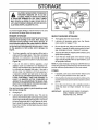
TO REPLACE
AUGER
,,,,
_
,u,_,,
+
ADJUST
H=,,
SHEAR
,=,,,,.
== ,,,,, mm
BOlT
,,,
==
==m,,m
,=
H
,,,m
mm
=,
E TS
'
,,,,,
,H
......................
,,,,
,, ...........
'......
The augers are secured to the auger shaft with special
bolts (See Fig. 37) that are designed to break (to protect
the machine) if an object becomes lodged in the auger
housing. Use of a harder bolt will destroy the protection
provided by the shear bolt..
IMPORTANT:
TO INSURE SAFETY AND
PERFORMANCE LEVELS, ONLY
ORIGINAL EQUIPMENT SHEAR
BOLTS SHOULD BE USED.
LOCKNUT
To replace a broken shear bolt, proceed as follows:
e
Move the throttle to STOP and turn off all controls..
e
Disconnect the spark plug wire. Be sure all moving
parts have stopped.
®
Lubricate the auger shaft zerk titting (see the Maintenance section, on pages 17-18)_
e
Align the hole in the auger with the hole in the auger
shaft Install the new shear bolt and Iocknut provided
e
Reconnect the spark plug wire
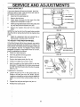
TO ADJUST
,I
FIG. 37
I
mS+A.CE
SHOtJ.O
.OTBE
GRATER
mAN=,NCHES
mACK
TRACK
If the snow thrower does not move forward evenly and the
track slips slightly, you need to check the track as follows:
e
Measure the distance between the top of the side
plate and the inside of the track, The distance
should not be more than two (2) inches
(A)
If the distance is greater, you need to adjust the track, as
follows:
e
Loosen the bolts (See F{g 38, A) on both sides of
the track assembly
•
Turn the cam washers equally on both sides
CAM
WASHER
FIG. 38
...................
f out OFAmUSmEN"r
....................
P*t
Adjust the track to reduce slack, so that the distance
between the top of the side plate and the inside of
thetrack is not greater than two (2) inches. Be sure
the cam washers are adjusted evenly or the track
will be twisted (See Fig 39). if the track becomes
twisted, readjust the cam washers to the correct
adjustment
%_
_
-.._---CORREOT
FRONT VIEW
,, ,,,
,m
FIG. 39
24
t
SERVICE AND ADJUSTMENTS
TO ADJUST
, ...................
CARBURETOR
CARBURETOR
The carburetor (See Fig. 40 and Fig. 42) has been pre-set
atthe factory and readjustment should not be necessary.
However, if the carburetor does need to be adjusted,
proceed as follows:
o
Close the high speed adjusting screw by hand
•
Do not overtighten.
i
IDLE ADJUSTING
(Close finger
®
Then ope n it 141/4 to t-1/2 turns
e
Close the idle adjusting screw by hand. Do not
overtighten
e
Then open it 1-1/4 to t-1/2 turns.
•
Start the engine and let it warm up.
®
Set the throttle control to FAST. Adjust the high
speed adjusting screw in until the engine speed or
sound alters Adjust the screw out until the engine
speed sound altersr Note the difference between
the two limits and set the screw in the middle of the
SCREW
tight only)
. ....
HIGH SPEED ADJUSTING
SCREW
(C!osefingertighlonly)
i
FIGo40
TO ADJUST:
o
Clean the spark plug by carefully scraping electrodes (do not sand blast or use a wire brush).
O
Be sure the spark plug is clean and free of foreign
matedal. Check electrodes gap (See Fig. 41) with a
wire feeler gauge and reset the gap to 030 inch if
necessary°
range.
®
Set the throttle control to SLOW Adjust the idle
adjusting screw in until the engine speed drops,
then adjust the screw out until the engine speed
drops. Note the difference between the two limits
and set the screw in the middle of the range.
®
If the engine tends to stall under load or not accelerate from low speed to high speed properly, adjust
the high speed screw out in 1/8 turn increments until
the problem is resolved
e
,030 GAP
Let the engine run undisturbed for 30 seconds
between each setting to allow the engine to react to
the previous adjustmenls
IMPORTANT:
NEVER TAMPER WITH THE ENGINE
GOVERNOR, WHlCH IS FACTORY
SET FOR PROPER ENGINE SPEED
OVERSPEEDtNG THE ENGINE
ABOVE THE FACTORY HIGH SPEED
SETTING CAN BE DANGEROUS.
IF YOU THINK THE ENGINE GOVERNED HiGH SPEED NEEDS
ADJUSTING, CONTACT YOUR
NEAREST SEARS SERVICE CENTER,
WHICH HAS THE PROPER
EQUfPMENT AND EXPERIENCE TO
MAKE ANY NECESSARY
ADJUSTMENTS.
ii
i
i
FIG. 41
TO REPLACE:
TO ADJUST OR REPLACE
THE SPARK PLUG
if you have difficulty starting your snow thrower, you may
need to adjust or replace the spark plug Follow the
instructions below
Replace the spark plug if electrodes are pitted or burned
or if the porcelain is cracked
25
e
If you need a new spark plug, use only the proper
replacement spark plug (See page 4 )
®
Set the gap to .030
•
Before installing the spark plug, coat its threads
lightly with graphite grease to insure easy removal.
o
Tighten the plug firmly into the engine
®
If a torque wrench is available, torque the plug to 18
to 23 ft - Ibs.
......................................
STORAGE
................
,11
ii
=ll= , H=
..............................................
,
,l=l=
,, ,i,l=
THROWER INDOORS OR IN AN ENCAUTION: NEVERSTOREYOURSNOW
CLOSED, POORLY VENTILATED AREA
IF GASOLINE REMAINS IN THE TANK. FUMES
MAY REACH AN OPEN FLAME, SPARK OR PILOT LIGHT FROM A FURNACE, WATER HEATER,
CLOTHES DRYER, CIGARETTE, ETC.
A
BOWL
DRAIN
To prevent engine damage ( if snow thrower is not used
for more than 30 days) follow the steps below
ENGINE
..........FIGo 42
STORAGE
SNOW THROWER
Gasoline must be removed or treated to prevent gum
deposits from forming in the tank, filter, hose, and
carburetor during storage. Also during storage, alcohol blended gasoline that uses ethanol or methanol (sometimes called gasohol) attracts water. It acts
on the gasoline to form acids which damage the
engine.
o
To remove gasoline, run the engine until the tank is
empty and the engine stops., Then drain remaining
gasoline from carburetor by pressing upward on
bowl drain located on the bottom of carburetor (See
Figure 42)r
Changing oil.
®
Lubricating the piston/cylinder area_ This can be
done by first removing the spark plug and squirting
clean engine oil into the spark plug hole Then cover
the spark plug hole with a rag to absorb oil spray
Next, rotate the engine by pulling the starter two or
three times, Finally, reinstall spark plug and attach
spark plug wire,
e
Thoroughly clean the snow thrower_
®
Lubricate all lubrication points (see the Maintenance section on pages 17-18).
®
Be sure that all nuts, bolts and screws are securely
fastened Inspect all visible moving parts for damage, breakage and wear. Replace if necessary_
®
Touch up all rusted or chipped paint surfaces; sand
lightly before painting.
o
Cover the bare metal parts of the blower housing
auger and the impeller with rust preventative, such
as sprayable lubricant
OTHER
o
If possible, store your snow thrower indoors and
cover it to give protection from dust and dirt
®
if the machine must be stored outdoors, block up the
snow thrower to be sure the entire machine is off the
ground.
Cover the snow thrower with a suitable protective
cover that does not retain moisture, Do not use
condi-
o
STORAGE
NOTE: A yearly checkup or tuneup by a SEARS Service
Center is a good way to insure that your snow thrower will
provide maximum performance for the next season.
If you do not want to remove gasoline, a fuel
stabilizer (such as Craftsman Fuel Stabilizer No.
33500) may be added to any gasoline left in the tank
to minimize gum deposits and acids if the tank is
almost empty, mix stablitizer with fresh gasoline in
a separate container and add some to the tank.r
ALWAYS FOLLOW INSTRUCTIONS ON STABILIZER CONTAINER. THEN RUN ENGINE AT
LEAST '10 MINUTES AFTER STABILIZER
IS
ADDED TO ALLOW MIXTURE TO REACH CARBURETOR, STORE SNOWTH ROWER IN A SAFE
PLACE. SEE WARNING ABOVE.
You can keep your engine in good operating
tion during storage by:
CARBURETOR
BOWL
plastic.
IMPORTANT:
26
NEVER COVER SNOW THROWER
WHILE ENGINE AND EXHAUST
AREAS ARE STILL WARM
EcoMM EN DATIO NS
SERVICE
RECORDS
Fill in dates as you complete regular service
SCHEDULE
After
First
Before
2
Often
Each
hours fuse
i
ii,ul
i
Every Every F{rstof i
10
25
Each
Before
Hours Hours Season Storage
v"
Check Engine Oil Leve!
v"
v"
Change Er_gine Oi!
it
I
v"
Tighten All Screws and Nuts
Check Traction Clutch Cable
v"
Adjustment (See Cable Adjustment)
, ,.
SERVICE
DATES
,.........
, .......
Replace Spark Plug
i,"
v"
v"
v"
.,,,,,, .............
Adjust Drive Belts
v"
Lubricate All Pivot Points
I
Lub;icate
AugerShaft(SeeShearBolt
v"
Replacement)
Lubricate Sprockets
and Chains
v"
v"
Sparingly (Track Assembly)
= ...............
:
,,,
Drain Fuel
Check Auger Clutch Cable
Adjustment (See Cable Adjustment}
Fric'iion Wheel zerk Fitiing (See
Maintenance)
LUBRICATION
CHART
Oil chains and
sprockets with
10W-30 oil
Lubricate
auger shaft,
Coat with a clinging type
grease such as Lubriplateo
ulllln,l,,
'1
.ll.,
hill
U,l.,
......................
,.i
27
...................
ii,
•
i
i
............
TROUBLE
....
m,,u,i
. m
SHOOTING PO! T$
nn ,,,Ul,,,,H,,,,,,,,,,,
TROUBLE
n,.,,
=ll
i nlnllU
,InllHI
IlUI.I II
Replace defective plug
Water or dirt in fuel system
Use carburetor
i
onfuel
bowl drain to flush and refill with fresh fuel
HHr
I HH,H,,,,,U
fuel (gasoline/oil
i1,11
,
Unit running on CHOKE
I
n
.......
mixture if 2 cycle engine)
ii
i
setchoke
Hun.
level" to RUN position
i,,
,,,,
...........
i
Engine runs erratic;
Use carburetor
Water or dirt in fuel system
bowl drain to flush and reflti with fresh
fuel
Loss of power
Carburetor out of adjustment
...............
Excessive
i,,
Clean fuel line; check tuel supply; add fresh
...................................
Engine stalls
ii ,i
'1 IIIll,,,,ll,,,lll
Defective spark plug
'"B'i ke' "fuel
line
Engine runs erratic
u,i
CORRECTION
CAUSE
Difficult starting
ut
nlu
,,n i,
vibration
.
Adjust carburetor,
,,u..,,
un
Loose parts; damaged impeller
iii
Stop engine immediately
and disconnect
Tighten all bolts and make all necessary
continues,
i
ilqUllln
Unit fails to propel
u
U,llll1,11,11
Ul
ii
i
ii
i u
spark plug wire
repairs
If vibration
have the unit serviced by a competent repairman
u ii
Drive belt loose or damaged
Replace drive belt
Incorrect adjustment
Adjust traction drive cable
itself
i, ii,, ,,
Worn or damaged fdclion wheel
Replace friction wheel
Auger drive belt loose or damaged
Adjust auger drive belt; replace if damaged
Auger control cable not adjusted
Adjust auger control cable
........
Unit fails to
discharge
of traction drive cable
snow
correctly
Shear boll broken
Replace shear bolt
Discharge chute clogged
Stop engine immediately
and disconnect
spark plug wire
Clean discharge chute and inside of auger housing
Foreign abject lodged in auger
Stop engine immediately
and disconnect
spark plug wire
Remove object from auger
n, ,,,
inll
Unit rides up
ii lUlls,,,
iiiii
iii
ii
iii iiiii i,ii,
Weight transfer disengaged
Engage weight transfer pedal
28
i itt,tt, lttlll.,
NOTES
i
c
29
CRAFTSMAN
32" TRAC-PLUS
Handle Assembly
SNOW THROWER
536.885020
Repair Parts
F---
73
58
\
3
1
3
74
1
60
9
72
71
.
_5
38
25
55
75
_
50 13
39
54 __
16
.17
24
18
17 48
16
10
2
11
17
22
57
19
35
46
17
45
17
48 ,.
42
17
44 43
21
16
4O
18
41
3O
43 44
CRAFTSMAN
REF.
NO.
PART NO.
1
2
8
10
1I
12
13
14
15
16
17
18
I
I
I
19
2O
21
24
25
28
I
27
28
31
32
I
33
34
35
36
37
38
39
4O
I
t
3535
70985
3538
310421
4049
308012
53861
70990
309793308037
71071
71059
71034
306523
310391
71042
71060
50782
6352
50786
71072
71038
1668
1578
7288
71062
71044
7289
71045
71457
308789
307913
1671
1673
71035
304872
307399
85192
148
71081
32" TRAC-PLUS
SNOW THROWER
PART NAME
Cap, Push, 5/6 In
Screw, 5/16-t8 x 3/4 In
Pivot Pin
Support, Control Panel Assembly
Bumper
Upper Handle
Control Knob
Screw, 5116-18 x 1-3/4 In
Socket, Headlight
Shift Lever
Flatwasher, 11/32 In
Lockwasher, 1/4 In_
Hex Nut, 1/4-20
Control Panel
Carriage Bolt, 1/4-20 x 2 In
Hex Nut, 5/t6-24
Lockwasher, 5/16 In
Ball Joint
Adaptor, Speed Control Rod
Spring
Flatwasher, 3/8 In
Locknut, Hex, 5/16-18
Rod, Speed Control
Clutch Cable
Screw, 3/8-16 x 3 In,
Lockwasher, Split, 3/8 In
Hex Nut, 3/8-16
Plastic Stop, 3/8 In
Nut, Hex Jam, 3/8-16
Eye Boll, 3/8_16 x 5 In
Decal, Control Panel
Lower Handle
Spring, Drive Clutch
Spring, Auger Clutch
Locknut, 1/4-20
Retainer Ring
Handle, Chute Crank
Crank Assembly
Grommet, Eye Bolt
Cotter Pin, 3/32 x 3/4 In
31
536.885020
RER
NO.
PART NO,
41
42
43
44
45
46
47
48
49
50
51
52
53
54
55
56
57
58
59
60
61
62
63
64
65
66
67
68
69
70
71
72
73
74
75
76
104
7055
7058
7059
70993
7052
7053
71037
580527
71007
3903
3902
6300
309344
308145
309312
308146
307395
305025
580530
307781
307767
580532
4160
309792
71061
71046
6636
235
308909
309789
309791
307918
307920
57444
307251
PART NAME
Plastic Cap
Rod, Chute Control
,Jam Nut, I/2-20
Lockwasher, Split, 1/2 In
Carriage Bolt, 5/16-18 x 3/4 In
Bracket, Chute Rotate L H
Bracket, Chute Rotate R H
Hex Nut, 5/I6-t8
Saddlewasher, 5/16 In
Hex Head Bolt, 3/8-16 x 2 In
Auger Drive Control Decal
Traction Drive Control Decal
Gear Selector Decal
Adaptor For Boot
Eyebott Boot
Flatwasher, 3/8 In
Clutch Spring Boot
Upper Housing, Headlight
Headlight Assembly
Lower Housing, Headlight
Screw, #10 x 1-3/4 In
Wiring Harness
Bracket, Headlight Mounting
Bolt, Carriage, 5/16-18 x 1-3/4 In
Metalized Back
Washer, External Lock
Locknut, Nylon, 3/8-t6
Conduit, Plastic
Screw Hex Head, 5/16-18 x 2 In
Screw, 10-24 x 5/8 tn
Lens, Headlight
Bulb, Headlight
Auger Drive Lever
Traction Drive Lever
Cable Tie
Owner's Manual
CRAFTSMAN
32" TRAC-PLUS
SNOW THROWER
536.885020
Motor Mount Repair Parts
65
14
17
60_'_
68 67
76
83
85 71
/
59
78
66
61
88
9t
7O
93
13
3
5
t3
36
9
3B
4
27
2B
56
52 51
50 53
55
57
32
93
13
7
CRAFTSMAN
REFo
NO.
1
2
3
4
5
6
7
8
9
10
tl
12
13
14
15
t6
17
18
19
20
21
22
23
24
25
26
27
28
29
30
3t
32
33
34
35
36
37
38
39
40
41
42
43
44
45
46
47
48
PART NO,
307923
55O7
307968
71067
70978
70982
5513
53703
71074
73801
85492
85494
71037
71060
71071
53713
70993
71062
7'1012
8220
307964
85187
51438
71393
70991
71362
70985
51445
71059
71034
71391
51477
50740
71073
1110
51448
71006
590
53696
50747
53720
53721
50677
71063
71128
169
71010
71072
32" TRAC-PLUS
SNOW THROWER
REF
NO,
PART NAME
Belt Cover
Motor Mount Frame
Engine Riser
FIatwasher, 1/4 In,,
Screw, Self-Tap,t/4
x 1/2 In
Screw, Self-Tap, 5/16-18 x 1/2 In
End Plate
Flanged Bearing
Flatwasher, 1/2 In,
Roll Pin, 5/32 x 7t8 In,,
Lever, Auger Clutch
Lever, Clutch Cable
Hex Nut, 5/16-18
Lockwasher, 5/16 In
Flatwasher, 5/16 In
Bracket, Clutch Adjustment
Carriage Bolt, 5116-1
3/4 In.
Lockwasher, 3/8 In.
Screw, Self-Tap, 3t8-16 x 1 In,
Bolt, 5/!6-18 x 2-112 In,
Engine, Craftsman, Model No,
143,8!6012 (See Er gine Repair
Parts List)
Belt Guard Plate
Spacer
Boll, 5/16-24 x 1 In
Bolt, 5/16-18 x 3 In.
Bolt, 516-18 x 2-3/4 In.
Bolt, 5/16-18 x 3/4 In
Rod, Spindle Suppor
Lockwasher, 1/4 In
1/4-20 Hex Nut
Nut, 5/16-18
Spring, Drive Idler
Shoulder Bolt, 5/16-1
Flatwasher, 7/16 In
Idler Drive Belt Brack _t
Idler Pulley, 3 In
Bolt, 3/8-16 x 1-1/4 lr
Nut, Jam, 3/8-16
Spindle Plate
Engine Pulley SpaceA
Pulley, Traction Drive
Pulley, Auger Drive
Washer
Lockwasher, 3/8 In
Belt, 3/8-24 x 1-!/4 In
Auger Clutch Rod As_
bly
Bolt, 3/8-16 x 1-1/2 In
Flatwasher, 3/8 In.
49
50
51
52
53
54
55
56
57
58
59
60
6t
62
63
64
65
66
67
68
69
70
71
72
73
74
75
76
77
78
79
8O
81
82
83
84
85
86
87
88
89
90
91
92
=
93 i
94
i
95
I
96
I
97 i
33
536.885020
PART NO.
71045
130
51458
50794
20556
50796
51224
307951
304129
4293
85214
50683
50684
50689
50690
70984
50654
85095
50666
50688
4051
3134
1413
50705
85204
51446
71081
50707
50798
50706
50700
30440
6550
7'1203
50704
5892
5898
71061
1795
71048
4062
50884
6177
50797
5954
85421
53710
50712
73795
PART NAME
Jam Nut, 3/8-16
Screw, 5/16-18 x 3/4 In.
Belt,Traction Drive, Special
Traction Pulley
Square Key
Auger Pulley 8 4 tn.
Belt, Auger Drive, Special
Rear Panel
Bottom Panel
Spring, Auger Brake
Friction Disc Assembly
Flatwasher
Beadng, Roller
Needle Bearing
Housing, Blade Shaft
Screw, Self-Tap, 5/16-18 x 3/4 In
Seal, Oil
Housing, Disc Drive
Flat'washer
Ring Retainer, 3/4 In
Spring Washer
Screw, 5/16-18 x 1/2 fn.
Bearing and Retainer Assembly
Drive Shaft Bearing
Clutch Plate
Yoke, Speed
Cotter Pin, 3/32 x 3/4 in.
Retainer
Chain
Drive Sprocket
Bearing, Clutch
Grease Fitting
Shaft & Gear Assembly
Key, 1/8 In.
Washer
Hub, Friction Wheel
Friction Wheel
Lockwasher, Ext, Tooth, 5/16 In
Cap Retainer, 3/8 In
Hex Nut, 3/8-24
Hex Shaft
Retainer
Axle
Chain
Bearing and Plate
Yoke, Drive
Spring, Clutch Yoke Return
Bushing
Flatwasher
CRAFTSMAN
32" TRAC-PLUS
SNOW THROWER
536.885020
Track Assembly
Repair
Parts
!_._ B 31 26B
21
2
t5
6
5
4
13
/,
11
/
22
1415
11
12 tl
16
17
41
34
5
CRAFTSMAN
REF,, I
NO. I PART NO.
308161
10900
I
10901
I
6025
I
518
I
6001
6888
I
71037
70985
I
I
71060
I
7089
5927
I
5916
J
I
5947
I
7'1067
I
6108
I
71348
5951
I
5950
I
5949
I
7086
I
I
7074
|
3
,4
5
6
....8
9
10
11
12
13
14
15
16
17
18
19
20
21
22
32" TRAC-PLUS
SNOW THROWER
536.885020
REF. 1
NO. 1 PART NO.
PARTNAME
Foot Pedal Assembly
Bracket, L H
Bracket, R H
Spring, Tension
Pal Nut, 1/2"
Shoulder Bolt, 5/16-18
Light Blue Decal
Hex Nut, 5/16-18
Screw, 5/16-18 x 3/4 In
Lockwasher, 5/16 In,,
Wheel, Track Drive
Sprocket Plate
Chain
Screw, 1/4-28 x 3-3/4 In,
Flatwasher, 1/4 In_
Locknut, 1/4-28
Screw, 5/16-18 x 1/2 In,
Bell Washer
Washer
Track
Shaft, Track Wheel
Hardened Washer, 1/2 In.
t
35
23
24
25A
25B
26A
26B
27
28
29
3O
31
32
33
34
35
36
37
38
39
4O
I
I
I
I
I
I
I
I
I
I
I
I
I
I
I
!
I
I
I
I
41
I
7087
305299
308914
308915
308034
308036
7048
7049
71035
70969
6403
304133
7106
73840
7285
73826
6049
20465
239
6177
308784
PART NAME
idler Wheel
Flatwasher, 3/4 In,
Track Plate, Inner L,H
Track Plate, Inner RH_
Track Plate, Outer LH
Track Plate, Outer R.H
Hub - Inner Bearing
Hub - Outer Bearing .......
Locknut, 1/4-20
Bolt, 1/4-20 x 1 In,
Cam Washer
Hub Sprocket Assembly
Spacer
Flatwasher
Screw, 1/4-20 x 1-1/2 In
Locknut, 1/4-20
Connecting Rod
Hair Pin
Retaining Ring
Axle & Sprocket Assembly
Trac-P]us Decal
_132"
23
\
20
\
\\
35
2_
33
3_
3O
37
2
-4
31
40
40
3_
CRAFTSMAN
32" TRAC-PLUS
SNOW THROWER
536.885020
m
REF:
NO.
PART NO.
1
2
3
4
5
6
307921
71037
71060
71071
1441
71147
7
8
9
10
11
12
13
14
15
16
17
18
19
20
21
22
23
24
25
71038
70993
71073
71072
57171
6711
307725
71032
71058
85113
309321
70969
71035
5500
308120
3316
70984
307912
70983
PART NAME
Chute Extension
Hex Nut, 5/1648
Lockwasher, 5/16 In
Flatwasher, 11/32"
Screw, 5/16-24 x 1-3/4 In
Pan Head Slotted Bolt, 5/16-18 x
3/4 in
Locknut, 5/16-18
Carriage Boil, 5/16-18 x 3/4 1N
Flatwasher, 7/16 In
Flatwasher, 3/8 In.
Wing Knob
Plastic Washer
Chute Deflector
Screw, #8-32 x 1/2 In
Locknut, #8-32
Retainer Ring
Flange, Chute Ring
Screw, 1/4-20 x 1 In
Locknut, 1/4-20
Auger Housing 32 In.
Side Plate, L H
Bolt, 5/16-!8 x 1 In
Screw, Self-Tap, 5/16-18 x 3/4 In.
Height Adjustor Skid
Screw, 5/16-18 x 5/8 In
'
37
REF.
NO.
PART NO.
26
27
26
29
30
31
32
33
34
35
36
37
38
39
40
41
42
43
44
45
46
47
48
49
50
308059
20556
85104
70986
308860
71100
308790
307911
307910
578647
308121
71391
10104
53757
50748
3O8766
130
50796
3362
71076
3194
7679
70141
7376
70142
PART NAME
Bearing, 7/8 In
Square Key
32" Scraper Bar
Bolt, 5/16-18 x 1 In
Gear Box Brace
Nut, 5/16-24
Size Decal
32 in Auger, L H
32 in.Auger, R H
Bolt, 5/16-18 x 2 In
Side Plate, R H
Locknut, 5/16-18
Grease Fitting
Bearing, Auger Shaft
Washer
Name Decal
Screw, 5/16-18 x 3/4 ln_
Auger Pulley 84 in
Rivet, 3/16 In
Flatwasher, 3/16 In
Skirt
Chute, Striped Danger Decal
Auger, Danger Decal
Impeller, Danger Decal
Chute, Danger Decal
CRAFTSMAN 32" TRAC-PLUS SNOW THROWER 536.885020
Gear Box Repair
Parts
17
18
19
20
21
3
5
22
1
tl
10
4
\
I
REF.I
NO. I
o
41
I
5!
61
81
91
101
111
12!
131
!4!
t51
PART NO.
1065
895
53743
20556
53748
73905
53730
897
73826
1403
1441
53737
53736
53735
53734
REF.
NO.,
PART NAME
Seal
16
17
18
19
Housing LH
Bearing, Auger Gear Box
Square Key
Flatwasher, 1"
Woodruff #91 Key
Worm Gear
Gasket, Gear Box
Locknut, 1/4-20
32" Auger Shaft
Screw, 5/t6-24 x 1-3/4"
Ring Quad
Bearing, Impeller Shaft
Flatwasher, 7/8"
Bearing, Roller
i 20
2t
22
i 23
24
I
,
25
E 26
i 27
28
29
38
PART NO.
53733
50795
53732
50683
5O688
53731
53749
1401
307909
896
71393
71100
73839
71067
PART NAME
Flatwasher, 7/8"
Key, Hi-Pro 606
Worm Gear
Flatwasher
Ring Retainer
Bearing, Impeller Shaft
Grease Plug
Shaft, Gear Box Input
Impeller
Housing, R H_
Screw, 5/16-24 x 1"
Flange Locknut, 5/16-24
Screw, 1/4-20 x 2-1/4"
Flatwasher, t/4"
REWIND
STARTER
NOo 590630
11
Ref.
No.
1
2
3
4
5
7
8
9
10
1!
12
39
Part
No.
Part
Name
590630
Starter, Rewind
590599A Pin, Spring (Incl. No 7)
59O6OO Washer
59O651 Spring Assy., Brake B Dog
590627 Retainer
59O641 Dog, Starter
590601 Washer
59O628 Pulley
590451A Rope, Starter
59O629 Spring B Keeper Assy,.
590574 Handle, Mitten Grip (Not included
with starter)
59O631 Housing Assy,, Starter
C_,FTSMAH
4=CY_=E
ENGIN_
MODEL:143.816012
1_310
34O
342_.
I
3O5
37
\
17'
B3
r81
87
t
396
69
_ODELendSERIAL
NUMBERSHERE
102
103
14
20
26
316
370C
4O
CRAFTSMAN
4-CYCLE
EHGINE
Ref.
Part
No.
No.
I
2
3A
3B
4
5
6
7
35371
65O820
34171
3O969
35319
27652
35326
650561
8
9
35443
34860A
9
34861
9
34862
9A
9A
34863
34864
9A
34865
10
11
11
!1
17
27888
34866A
34867
34868
35373A
18
19
19A
20
21
35374
6509O8
650882
34034
35375
22
23
24
25
33273A
650128
*35262
35376
26
27
33
35377
35319
30699C
34
35
36
37
38
39
4O
41
42
43
30700
650494
29642
31845
30588A
35479
29193
35378
33369
650838
49
50
51
52
53
54
55
56
29916
28826
29216
33454
29918
65O548
30322
650832
57
650833
58
59
6O
62
66
35565
35499
35554
3554O
27878A
MODEL:143.816012
Refo
No.
Part Name
(InClr Nos. 3, 4 e 5)
Screw, Hex hd, shoulder, 114-20 x 112
Nipple, Pipe, 5.1/2"
Cap, Oil drain
Seal, Oii
Pin, Dowel
Baffle, Blower housing
Screw, Hex washer hdo Durlok, 1/420
x 5/8
Crankshaft
Piston, Pin _f Ring Assy. (tnc}. NOSo
9A, t0 E_11) (std.)
Piston, Pin e Ring Assy. (inc!. Nos,.
9A, 10 8- 11) (o010 oversize)
Piston, Pin _ Ring Assy. (Incl. Nos.,
9A, 10 Et tl) (.020 oversize)
Piston e Pin Assy. {lncL No. 10) (Stdr)
Piston _ Pin ASSyr (Inclo No, 10) (..010
oversize)
Piston e Pin Assy, (Incl. Noo 10) (.020
oversize)
Ring, Piston pin retaining
Ring Set, Piston (Std,)
Ring Set, Piston (o010 oversize)
Ring Set, Piston (4020 oversize)
Rod Assyo, Connecting (Inclo Noso I8,
19 _ 19A)
Dipper, Oil
Bolt, Connecting rod
Bolt, Connecting rod
Lifter, Valve
Camshaft (Mechanical Compression
Release)
Extension, Blower housing
Screw, Hex hd_ Seres, 10-24 x t/2
Gasket, Cyllnder cover
Cover Ass,/., Cylinder (Inclo Nos. 26,
27 E_37)
Bushing, Cylinder cover
Seat, Oil
Rod Assyo, Governor (Incl. Nos,. 34
35)
Yoke, Governor
Screw, Fil, hdo Seres, 6-40 x 5/16
Ring, Retaining
Shaft, Governor
Spool, Governor
Washer, Fiat
Ring, Retaining
Gear, Govenor (Inci, No. 39)
Bracket, Governor gear
Screw, Hex washer hd. thread forming, 10_24x 1/2
Clamp, Governor lever
Screw, Hex washer hd,, 10-32 x 3/4
Locknut, Hex "Keps', 10-32
Lever, Governor
Washer, E,T. Lock
Screw, Hex washer hd., 832 x 5/16
Locknut, Hex "Keps", 8-32
Screw, Hex washer hd. Powerlok,
1/4-20 x 1-I!/16
Screw, Hex washer hd. Powerlok,
1/420 x 1-3/16
Dipstick, Oil
"0" Ring
Tube, Oil fill
Clip, Fill tube
Valve, Exhaust (Inci. No. 70) (Std_)
Cytinder
41
Part
No.
66
27880A
67
67
34035
34036
68
68A
69
7O
76
77
78
79
8O
81
82
82A
83
27882
34689
27881
32581
32589
29443
611093
650880
650881
650872
35135
610118
650814
85
86
95
96
97
98
99
650873
611111
35253
34923A
34O3O
6O21A
33636
100
101
65O691
650727
102
103
104
lO5
106
107
108
lO9
t14
t15
117
118
119
65O69O
650694A
"27896A
28423
28424
28425
35350
650128
29752
*33263
33877
30088A
650378
120
121
t22
123
t24
*27915A
34567
28820
33377
650767
t30
131
132
133
35447
570682
32180C
34677
134
135
136
t37
31342
650549
610973
650821
138
139
140
34663
34667
3_3878
Part
Name
Valve, Exhaust (Incl. No. 70) (1/32"
oversize)
Valve, Intake (incL No. 70) (Std.)
Valve, lntake (lneL No, 70) (1/32"
oversize)
Cap, Upper vatve spring
Seal Assy,, Intake valve
Spring, Valve
Cap, Lowr valve spring
Key, Flywheel
Cllp, Spring
Flywheel (w/ring gear)
Washer, Lock
Nut, Flywheel
Stud, Solid state mounting
Solid, State Assy.
Cover, Spark plug
Screw, Torx Hex washer hd. Sems,
10-24 x 1
Screw, Hex hd Seres, 1/4-20 x 3/4
Coil Ass,/., Alternator (1B Watt)
Wire, Ground
Gasket, Cyllnaar head
Head, Cylinder
Screw, Hex flange hdo, 5/16-1B x t- 1/2
Spark
Plug (Champion
J-BC or
equivalent)
Washer, Flat
Screw,
Special hex hdo tapped,
5/16-18 x 1-3/4
Washer, Beflevitle
Screw, Hex flange hd., 5/16-18 x 2
Gasket, Breather
Body, Breather
Element, Breather
Cover, Breather
Tube, Breather
Screw, Hex hd. Seres, t0-24 x 1/2
Nut _ Lockwasher, 1/4-28
Gasket, Carburetor
Pipe, Intake
Screw, Fil. hd. Sems, 1/4-28 x 1
Screw, Torx ill. hd. Sems, 5/16-18 x
1-118
Gasket, Intake pipe
Bracket, Choke
Screw, Filo hd Sems, 10-32 x 1/2
Bracket, Carburetor cover mounting
Screw, Hex washer hd Sems, taptite,
8-36 x 5/8
Housing, Blower
Primer Assy,
Line, Primer
Bracket Ass,/,, Control (incl. Noso 134,
135, 136 Ef 138)
Spring, Compression
Screw, Filo hd, 5-40 x 7/16
Terminal Assy.
Screw, Hex washer hd. thread cutting,
10-32 x 1/2
Spring, Speed control
Link, Governor
Link, Governor-to-throttle
*Indicates Parts Included in
Gasket Set, Ref_ No_ 215.
4= ¢LE EHGINE
No.
i
Part
No.
281
282
285
285
287
29O
292
298
33013
650760
35287
35446
29752
30705
300
301
305
306
308
310
314
316
322
325
327
328
329
330
336
34156A
35355
35554
35499
35540
35555
650873
611111
611118
29443
35392A
PEtName
2646O
65O665
35593
610873
3,53O5
650765
337
338
35057A
28942
CARBURETOR
MODEL:143.816012
] tel.
i qo.
Part
No.
_t0
H2
54155
650561
Cover, Starter hole
Screw, Pan hd° taptite, 8_32 x 3/8
Hub, Starter
Screen, Starter
Nut e Lockwasher, 1/4-28
Line, Fuel
Clamp, Fuel line
Screw, Hex washer hd, thread cutting,
1/4-t5 x7/8
Tank, Fuel (Incl. Nos. 292 _ 301)
Cap, Fuel tank
Tube, Oil fill
"O" Ring
Clip, Fill tube
Dipstick, Oil
Screw, Hex hd. Seas, t/4-20 x 3/4
Coil Assy., ARemator (t8 Watt)
Body Connector
Clip, Spring
Plug, Starter
Key, Ignition
Terminal Assy.
Wire, Ground
Screw, Hex washer hd+ self-drilling,
10-32 x t/2
Cover, Carburetor
Screw, Hex washer hd. Sems, 10-32 x
Bracket, Fuel tank
Screw, Hex washer hd. Durlok, t/4-20
x 5/8
34154
P_ate, Fuel tank mounting
570682
Primer Assy,
32160C
Line_ Primer
590574
Starter Handle, Mitten grip
33377
Bracket, Carburetor cover mounting
650767
Screw, Hex washer hd_Sems, taptite,
8-32 x 27/64
35878
Decal, Instruction
35077
Decal, Choke
34144
Decal, Primer
632370A Carburetor (Incl, Noo 224)
590630
Starter, Rewind
Electric Starter Kit No, t43.88924 (Optional) Order as Accessory.
33279G
Gasket Set (IncL items marked *)
345
350
351
355
364 _
365
370
370B
370C
380
390
396
40O
RPM Settings:
High Speed: 3550 - 3650
Low Speed: 1700
*indicates Parts Included in
Gasket Set, Ref. No. 400.
3/8
NO.
632370A
14
/_.
15
17 _--_
10
I
5
24
23--"
27 --_
28
Part Name
20
5A
21__
42
m
.
Re{.
No.
I
I
Part
No.
Part Name
632370A Carburetor
631776A Shaft et Lever Assy., Throttle
Spring, Throttle return
t' 631970
3 I 631776
Shutter, Throttle
t 650506
Screw, Throttle _ Choke shutter
5 I 630766
Spring, Regulating
screw
5A I 630738
Spring, Main adjustment
screw
6 I 650417
Screw, Idle regulating
' 632112
Shaft _ Lever Assy., Choke
8 I 630735
Spring, Choke positioning
9 I 632174
Shutter,
Choke
10 1"630748
Plug, Welch
11 !'63!027
Plug, Welch
Inlet Needle,
Seat _ Clip Assy
12 1"631021
Incl. No, 13)
13 I 631022
Clip, Inlet needle
14 I 632019
Float, Carburetor
15 1"631024
Shaft, Float
16 ! 631951
Bowl, Float (IncL Nos. 17 et 18)
"_ ' 27136A Plunger Assy, Drain (lncL NOo t8)
18 I 27554
Gasket, Drain
20 1"632239
Adjustment
Screw
Assy.,
Main
{Inclo Nos. 5A, 21, 23 _ 27)
Gasket, Bowl-to-body
21
27110
23 *63074O "O" Ring, Adjustment
screw
24
632281
Screw, idle adjustment
25 *631026
Gasket, Bowl-to-body
26
632164
Fitting, Fuel inlet
27
630739 Washer
28
632347
Repair Kit (Inc!. items marked *)
NOTES
43
®
!!_ 2 +
OWN
R'S
UAL
10 HORSEPOWER
32" DUAL STAGE
TRAC=.PLUS
120V. ELECTRIC START
SNOW THROWER
MODEL NO.
,885020
Each SNOW THROWER
has its own MODEL
NUMBER found on the motor mount frame+
Each ENGINE has its own MODEL
found on the BLOWER HOUSING°
NUMBEF_:
Always mention these MODEL NUMBERS when
requesting service or Repair Parts for your SNOW
THROWER+
All parts listed herein may be ordered through
any Sears Service Center/Departments
and most
Sears Stores,,
WHEN ORDERING
REPAIR
GIVE THE FOLLOWING
PARTS,
ALWAYS
INFORMATION:
* PRODUCT - "SNOW THROWER"
* MODEL NUMBER - 536.885020
HOW TO ORDER
REPAIR PARTS
* ENGINE MODEL NUMBER 143.816012
* PART NUMBER
* PART DESCRIPTION
"Your Sears merchandise has added value when you
consider that Sears has service units nationwide staffed
with Sears trained technicians+.,.Professional technicians
specitically trained on Sears Products, having the pads,
tools and equipment to insure that we meet our pledge
to you.....we service what we sell."
UnlU,
i
inlu
u,,u,,i ,,,nu ,i
i i,lUll,,_,P
...........
SEARS, ROEBUCK AND CO., Chicago, IL 60684
307251 08t27t90
Printed in U.S.A.