1
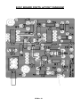
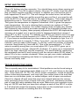
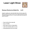
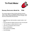
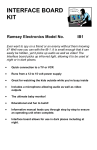
Electronic Cricket
Sensor
Ramsey Electronics Model No.
ECS1
What’s that peeping? Must be the crickets outside. Wait, no it’s
the ECS1! Tell the temperature by counting the chirps. An easy
to build kit for all ages . What fun is it to look at a thermometer, I
ask you! Get a cricket and have a fun conversation piece!
•
Works as a thermometer just like a real cricket
•
Tells temperature by the rate of chirping
•
Runs on a 9V battery.
•
Adjustable chirp rate for calibration
•
Adjustable chirp sound
•
Hide this miniature kit anywhere and watch the fun as friends try to
find the “cricket “ in the house!
ECS1• 1
PARTIAL LIST OF AVAILABLE KITS:
RAMSEY TRANSMITTER KITS
• FM10A, FM25B FM Stereo Transmitters
• AM1, AM25 Transmitter
• PPM3 Phone Patch Mixer
RAMSEY RECEIVER KITS
• FR1 FM Broadcast Receiver
• AR1 Aircraft Band Receiver
• SR2 Shortwave Receiver
• AA7 Active Antenna
• SC1 Shortwave Converter
RAMSEY HOBBY KITS
• SG7 Personal Speed Radar
• SS70A Speech Scrambler/Descrambler
• TT1 Telephone Recorder
• WEB1 Walking Electronic Bug
• UAM2 20W Audio Amplifier
• PG13 Plasma Generator
• MD3 Microwave Motion Detector
• TFM3 Tri-Field Meter
RAMSEY AMATEUR RADIO KITS
• HR Series HF All Mode Receivers
• DDF1 Doppler Direction Finder Kit
• QRP Series HF CW Transmitters
• CW7 CW Keyer
• QRP Power Amplifiers
RAMSEY MINI-KITS
Many other kits are available for hobby, school, scouts and just plain FUN. New
kits are always under development. Write or call for our free Ramsey catalog.
ECS1 Electronic Cricket Sensor
Ramsey Electronics publication No. ECS1 Rev. 1.1
January 2004
COPYRIGHT ©2003 by Ramsey Electronics, Inc. 590 Fishers Station Drive, Victor, New York
14564. All rights reserved. No portion of this publication may be copied or duplicated without the
written permission of Ramsey Electronics, Inc. Printed in the United States of America.
ECS1• 2
Ramsey Publication No. ECS1
Manual Price Only $5.00
KIT ASSEMBLY
AND INSTRUCTION MANUAL FOR
Electronic Cricket
Sensor
TABLE OF CONTENTS
Introduction to the ECS1 ................................... 4
ECS1 Circuit Description ................................... 4
“Learn-As-You-Build” Kit Assembly.................... 6
Parts List............................................................. 7
Assembly Steps.................................................. 8
ECS1 Parts Layout Diagram ............................ 10
ECS1 Schematic .............................................. 11
Setup and Testing ........................................... 12
Troubleshooting Guide ..................................... 12
Ramsey Kit Warranty........................................ 15
RAMSEY ELECTRONICS, INC.
590 Fishers Station Drive
Victor, New York 14564
Phone (585) 924-4560
Fax (585) 924-4555
www.ramseykits.com
ECS1• 3
INTRODUCTION
Everyone has heard the crickets outside their window peep, peep, peeping,
but some people don’t know that those chirps can be used to measure
temperature! If you count the number of chirps in 15 seconds and add 40,
you have roughly the Fahrenheit temperature. Isn’t that swell? The ECS1 is
an electronic version of those little temperature telling crickets. It will chirp to
temperature just like them. So all you do is build it, tweak it, then: peep, peep
peep, “Hey it’s 72 degrees out”.
ECS1 CIRCUIT DESCRIPTION
Well for all of you who haven’t seen enough of the uber-classsic LM555 timer
IC, this circuit is for you. If by some chance there is someone who has not
used one before, this kit will indoctrinate you into the “in” crowd and you will
now be cool. There be three timers: U1, U2, and U3. They have teamed up
to create the sound of the cricket. Before you understand the electronics you
must understand the cricket chirp. I, the kit designer, have spent much time
learning about this so that my kit will sound right. So, now you, the kit builder,
shall be enlightened. A cricket chirp is composed of a group of three
amplitude modulated sine waves occurring in rapid succession. Observe the
picture. Each group of three is one chirp. This picture is an actual output from
a wave file of recorded cricket sound. When it is played the result is: “chirp
chirp chirp”. If you zoom way in on one chirp it looks like the next picture.
As you can see, it is made up of a sine wave of a single frequency (about
5KHz) that ramps up and then back down again. This is the essence of the
cricket chirp. The ECS1 is meant to reproduce this closely enough that it
ECS1• 4
sounds like a cricket chirp. The circuit responds to temperature by way of a
thermistor, a resistor whose value changes with temperature. The thermistor
is used as a timing resistor in U1. When the temperature changes, U1’s
output frequency changes and so does the cricket chirp rate. In order to keep
the circuit simple and inexpensive, some compromises had to be made. The
main one is that the circuit is composed of elements that produce square
waves, not sine waves. For audio guys, this may cause foaming at the
mouth, but you can get some square waves to sound almost the same as a
sine wave if you tweak everything right. To try to match the cricket chirp
waveforms as closely as possible, three 555 timers are used. They are
chained together in such a way that they modulate each other. The output of
the first modulates the second, and the output of the second modulates the
U1 Out
U2 Out
U3 Out
third. Look upon the picture above. Keep in mind that this diagram just shows
the “relative” frequencies generated by the three timers so you can see how
the different waveforms look. In reality the output of U3 is much higher
frequency, but if drawn that way would be too hard to see on this picture. As
you can see the pulses from each 555 build up the final waveform. You will
notice that the final waveform from U3 has groups of 4 pulses not three. This
goes back to what was said about tweaking a circuit that produces square
waves so that it sounds like the original sine wave pattern. By listening to the
sound the circuit made as I adjusted the timings of the 555 timers, I found
that these timings worked best. The circuit has a pot that will let you change
the frequency of U3 so you can tweak the pitch of the cricket sound to your
liking. The last stage in the circuit is an output transistor that drives the
speaker.
ECS1• 5
RAMSEY Learn-As-You-Build KIT ASSEMBLY
There aren’t that many solder connections on the ECS1 printed circuit board,
but you should still practice good soldering techniques.
•
•
•
•
Use a 25-watt soldering pencil with a clean, sharp tip.
Use only rosin-core solder intended for electronics use.
Use bright lighting; a magnifying lamp or bench-style magnifier may
be helpful.
Do your work in stages, taking breaks to check your work. Carefully
brush away wire cuttings so they don't lodge between solder
connections.
We have a two-fold "strategy" for the order of the following kit assembly steps.
First, we install parts in physical relationship to each other, so there's minimal
chance of inserting wires into wrong holes. Second, whenever possible, we
install in an order that fits our "Learn-As-You Build" Kit building philosophy.
This entails describing the circuit that you are building instead of just blindly
installing components. We hope that this will not only make assembly of our
kits easier, but help you to understand the circuit you’re constructing.
For each part, our word "Install" always means these steps:
1. Pick the correct part value to start with.
2. Insert it into the correct PC board location.
3. Orient it correctly, follow the PC board drawing and the written
directions for all parts - especially when there's a right way
and a wrong way to solder it in. (Diode bands, electrolytic
capacitor polarity, transistor shapes, dotted or notched ends
of IC's, and so forth.)
4. Solder all connections unless directed otherwise. Use enough heat
and solder flow for clean, shiny, completed connections.
ECS1• 6
ECS1 PARTS LIST
Sort and “check off” the components in the boxes provided. We do our best to
pack all our kits correctly but it is possible that a mistake has occurred and we
missed a part. Please note that physical descriptions of parts are for those
currently being shipped. Sometimes the parts in your kit may have a different
appearance but still have the same values.
RESISTORS
1
1
2
1
1
1
1
1
1
100 ohm resistor [brown-black-brown] (R10)
470 ohm resistor [yellow-violet-brown] (R6)
1K ohm resistor [brown-black-red] (R5,R8)
10K ohm resistor [brown-black-orange] (R1)
100K ohm resistor [brown-black-yellow] (R4)
1K ohm potentiometer [orange top marked 102] (R9)
5K ohm potentiometer [orange top marked 502] (R7)
500K ohm potentiometer [orange top marked 504] (R2)
100k thermistor (R3)
CAPACITORS
3
5
1
1
.01 uF ceramic disk capacitor [marked 103] (C7,C9,C10)
.1 uF ceramic disk capacitor [marked 104] (C3,C4,C5,C6,C8)
100 uF electrolytic capacitor (C2)
2.2uF electrolytic capacitor (C1)
SEMICONDUCTORS
3
4
1
1
555 Timer IC [marked NE555N] (U1,U2,U3)
1N4148 diode (D1,D2,D3,D4)
78L05 voltage regulator (VR1)
BS170 FET (Q1)
MISCELLANEOUS
1
1
1
1
red/black twisted wire, 4 inches
DPDT switch
8 ohm speaker
9V battery connector
ECS1• 7
ECS1 PC BOARD ASSEMBLY STEPS
1. Take a look at the layout diagram. Let’s start with the bottom left of the
board and install power switch S1. Be sure to use enough solder to firmly
attach it to the board.
2. Next, install D2, 1N4148 diode, to the right at the bottom of the board.
Be sure it goes in the right way. Line up the black band on the part with
the white band on the board drawing.
3. Install R2, 500K potentiometer [marked 504], to the right of D2.
4. Install R3, 100K thermistor, next to R2. This is the temperature sensor
for your kit. At this point you can solder in the part directly to the board, or
solder it to the end of a wire, and then solder the wire into the board. Using the wire method, you can place the thermistor a distance away from
the board to measure temperature remotely. You can use the included
wire, or your own wire, if you want it to be longer. If you decide to solder
the thermistor onto the end of a wire, wrap some tape around the leads
just to keep them from bending and possibly breaking off.
5. Install D1, 1N4148 diode, above D2. Watch the polarity again.
6. Install R1, 10K ohm resistor [brown-black-orange], above R2.
7. Install C1, 2.2 uF electrolytic capacitor, above D1. Watch the polarity on
this part too. Make sure the “-” lead goes in the “-” hole, and the “+” lead
goes in the plus hole. There is a band on your cap marking “-” and a “+”
symbol on the board.
8. Install U1, the first of a trio of 555 timers. Make sure the notch on the
chip lines up with the notch on the board drawing.
9. Install Q1, BS170 “power” transistor. Power is in quotes because of a
running argument between myself and another engineer here about MOSFETS. For a tad more $$, I could have put a part in this kit that could start
your car, but I SUPPOSE it isn’t necessary for driving a small speaker. I
digress. Make sure Q1 goes in the right way. Line up the flat spot with the
flat spot on the board drawing.
10. Install R9, 1K ohm potentiometer [marked 102], to the right of Q1.
11. Install C10, .01 uF ceramic disc capacitor [marked 103], above R9.
12. Install C9, .01 uF ceramic disc capacitor [marked 103], above C10.
13. Install C7, .01 uF ceramic disc capacitor [marked 103], above C10.
14. Install C5, .1 uF ceramic disc capacitor [marked 104], above C9.
ECS1• 8
15. Install D4, 1N4148 silicon diode, above C5. Watch the polarity.
16. Install R5, 1K ohm resistor [brown-black-red], above D4.
17. Install D3, 1N4148 diode, right next to R5. Once again, don’t put it in
backwards just to be a rebel.
18. Install R4, 100K resistor [brown-black-yellow], next to D3.
19. Install R6, 470 ohm resistor [yellow-violet-brown], next to R4.
20. Install U2, 555 timer IC under R4. Line up the notch like you did with
U1.
21. Install C3, .1 uF ceramic disc capacitor [marked 104], just to the left of
U2.
22. Install R10, 100 ohm resistor [brown-black-brown], to the left of C3.
23. Install C2, 100 uF electrolytic capacitor, below C3. Follow the silkscreen for polarity!
24. Install R8, 1K ohm resistor [brown-black-red], below C2.
25. Install C4, .1 uF ceramic disc capacitor [marked 104], to the left of C2.
26. Install R7, 5K ohm potentiometer [orange top marked 502], to the left
of R10.
27. Install C8, .1 uF ceramic disc capacitor [marked 104], above R7.
28. Install U3, the last of the 555 timers, under R7. Line up the notch
again.
29. Install C6, .1 uF ceramic disc capacitor [marked 104], next to C6.
30. Install VR1, 5V low power voltage regulator, next to C6. Line up the
flat side with the flat spot on the board drawing.
31. Solder in the 9V battery connector into pads P1 and P2. The black
wire goes into P2 and the red one goes into P1.
32. Solder in the speaker to pads P3 and P4 using the included wire or
your own. It doesn’t matter what wire goes into which pad.
Okay, enough of all of this stuff. Time to test it out!
ECS1• 9
ECS1 BOARD PARTS LAYOUT DIAGRAM
ECS1• 10
ECS1 MAIN BOARD SCHEMATIC
ECS1• 11
SETUP AND TESTING
Plug a 9V battery into the connector. You should hear some chirps coming out
of the speaker. Turn R9 to adjust volume. Now turn R7 slowly to get the pitch
that you think sounds most like a cricket. In addition you can remove one or
both capacitors C9 and C10. This will change the sound more, but will also
reduce volume. When you get the sound the way you like it, you need to calibrate the ECS1 so that it will chirp to the right frequency. The cricket-chirp-totemperature rule is: Count the number of chirps in 15 seconds and add 40.
This gives the temperature in degrees Fahrenheit. Well, it gives the approximate temperature. No one is claiming that a cricket can replace a Fluke™
temperature probe. However, the cricket chirping does increase very linearly
with frequency and is plenty accurate enough for an interesting fireside conversation starter. Anyway, when properly adjusted the ECS1 will duplicate the
accuracy of a cricket over a typical cricket’s chirping temperature range of
about 55°F to 90°F or more. To calibrate your ECS1 you need to turn it on and
set R2 such that the chirp frequency is 2.13Hz, or 128 chirps per minute at 72°
F. If you have an oscilloscope you can measure the frequency of pin 3 on U1
and adjust R2 until it is exactly 2.13Hz. If you don’t, you can use the counting
method; it will just take a little longer. To do this, count the number of chirps in
a minute. Now divide by 4 and add 40. This is the temperature in °F. If this
value is woefully wrong then you must adjust R2. If your ECS1 gives you a
temperature that is too low, adujust R2 clockwise. If it gives you a temperature
that is too high, adjust R2 counter-clockwise. You should start by measuring
the resistance across R2 and turning it until the value is about 30.2K ohms, or
about 2/3 of a turn counter-clockwise. When you get your cricket calibrated,
put it somewhere interesting and listen to it peep peep until it drives your
friends and family mad.
TROUBLESHOOTING GUIDE
This is a pretty easy kit to troubleshoot. Most problems can be found using a
clear head and a logical approach. Make sure U1, U2, and U3 are in the right
way. Then check Q1, D1, D2, D3, D4 for proper orientation. Check all parts for
correct value and placement, and look over your solder joints to be sure that
there are no cold solder joints, no solder bridges, and no open connections.
Check for clipped off lead ends that may have lodged between the connections causing a short. Have a friend look over your work; sometimes another
pair of eyes will catch mistakes that we miss. Make sure your regulator is putting out +5VDC and that you have that voltage on each of the 555 IC s at pin
8. If all else fails check the warranty instructions on the inside back cover of
this manual for details on sending the kit in for repair.
ECS1• 12
CONCLUSION
We sincerely hope that you will enjoy the use of this Ramsey product. As always, we have tried to compose our manual in the easiest, most “user
friendly” format that is possible. As our customers, we value your opinions,
comments, and additions that you would like to see in future publications.
Please submit comments or ideas to:
Ramsey Electronics Inc.
Attn. Hobby Kit Department
590 Fishers Station Drive
Victor, NY 14564
or email us at: [email protected]
And once again, thanks from the folks at Ramsey!
ECS1• 13
ECS1• 14
The Ramsey Kit Warranty
Please read carefully BEFORE calling or writing in about your kit. Most
problems can be solved without contacting the factory.
Notice that this is not a "fine print" warranty. We want you to understand your rights and ours too! All
Ramsey kits will work if assembled properly. The very fact that your kit includes this new manual is
your assurance that a team of knowledgeable people have field-tested several "copies" of this kit
straight from the Ramsey Inventory. If you need help, please read through your manual carefully, all
information required to properly build and test your kit is contained within the pages! However,
customer satisfaction is our goal, so in the event that you do have a problem, take note of the
following.
1. DEFECTIVE PARTS: It's always easy to blame a part for a problem in your kit, Before you conclude
that a part may be bad, thoroughly check your work. Today's semiconductors and passive components
have reached incredibly high reliability levels, and its sad to say that our human construction skills
have not! But on rare occasions a sour component can slip through. All our kit parts carry the Ramsey
Electronics Warranty that they are free from defects for a full ninety (90) days from the date of
purchase. Defective parts will be replaced promptly at our expense. If you suspect any part to be
defective, please mail it to our factory for testing and replacement. Please send only the defective part
(s), not the entire kit. The part(s) MUST be returned to us in suitable condition for testing. Please be
aware that testing can usually determine if the part was truly defective or damaged by assembly or
usage. Don't be afraid of telling us that you 'blew-it', we're all human and in most cases, replacement
parts are very reasonably priced.
2. MISSING PARTS: Before assuming a part value is incorrect, check the parts listing carefully to see
if it is a critical value such as a specific coil or IC, or whether a RANGE of values is suitable (such as
"100 to 500 uF"). Often times, common sense will solve a mysterious missing part problem. If you're
missing five 10K ohm resistors and received five extra 1K resistors, you can pretty much be assured
that the '1K ohm' resistors are actually the 'missing' 10 K parts ("Hum-m-m, I guess the 'red' band
really does look orange!") Ramsey Electronics project kits are packed with pride in the USA. If you
believe we packed an incorrect part or omitted a part clearly indicated in your assembly manual as
supplied with the basic kit by Ramsey, please write or call us with information on the part you need
and proof of kit purchase.
3. FACTORY REPAIR OF ASSEMBLED KITS:
To qualify for Ramsey Electronics factory repair, kits MUST:
1. NOT be assembled with acid core solder or flux.
2. NOT be modified in any manner.
3. BE returned in fully-assembled form, not partially assembled.
4. BE accompanied by the proper repair fee. No repair will be undertaken until we have received the
MINIMUM repair fee (1/2 hour labor) of $25.00, or authorization to charge it to your credit card
account.
5. INCLUDE a description of the problem and legible return address. DO NOT send a separate letter;
include all correspondence with the unit. Please do not include your own hardware such as nonRamsey cabinets, knobs, cables, external battery packs and the like. Ramsey Electronics, Inc.,
reserves the right to refuse repair on ANY item in which we find excessive problems or damage due to
construction methods. To assist customers in such situations, Ramsey Electronics, Inc., reserves the
right to solve their needs on a case-by-case basis.
The repair is $50.00 per hour, regardless of the cost of the kit. Please understand that our technicians
are not volunteers and that set-up, testing, diagnosis, repair and repacking and paperwork can take
nearly an hour of paid employee time on even a simple kit. Of course, if we find that a part was
defective in manufacture, there will be no charge to repair your kit (But please realize that our
technicians know the difference between a defective part and parts burned out or damaged through
improper use or assembly).
4. REFUNDS: You are given ten (10) days to examine our products. If you are not satisfied, you may
return your unassembled kit with all the parts and instructions and proof of purchase to the factory for
a full refund. The return package should be packed securely. Insurance is recommended. Please do
not cause needless delays, read all information carefully.
ECS1• 15
ECS1 Quick Reference Page Guide
ECS1 Circuit Description................................... 4
Parts List............................................................. 7
ECS1 Parts Layout Diagram ............................ 10
ECS1 Schematic .............................................. 11
Setup and Testing ........................................... 12
Ramsey Kit Warranty ....................................... 15
REQUIRED TOOLS
• Soldering Iron (WLC100)
• Thin Rosin Core Solder (RTS12)
• Needle Nose Pliers (MPP4 or RTS05)
• Small Diagonal Cutters (RTS04)
ADDITIONAL SUGGESTED ITEMS
Helping Hands Holder for PC Board/Parts
(HH3)
• Technician’s Tool Kit (TK405)
• Desoldering Braid (RTS08)
•
Manual Price Only: $5.00
Ramsey Publication No. ECS1
Assembly and Instruction manual for:
RAMSEY MODEL NO. ECS1 Electronic
Cricket Sensor.
RAMSEY ELECTRONICS, INC.
590 Fishers Station Drive
Victor, New York 14564
Phone
(585) 924-4560
Fax
(585) 924-4555
www.ramseykits.com
ECS1• 16
TOTAL SOLDER POINTS
95
ESTIMATED ASSEMBLY
TIME
Beginner ...............1.5 hrs
Intermediate .........1 hrs
Advanced ..............30 min