1
OWNER'S
MANUAL
®
Caution:
Read and follow
all Safety Rules
and Instructions
Before Operating
This Eqmpment
18°0 P TW_ CYUNDER
44"'MOWER
G SPEED
GARDEN TRACTOR
° AssembBy
° Operation
° Customer Responsibilities
• Service and Adjustments
° Repanr Parts
Sears, Roebuck
and Co., Hoffman
Estates,
IL 60179 U.S.A.
SAFETY
Safe Operation
Practices RULES
for Ride-On Mowers
&
IMPORTANT: THIS CUTTING MACHINE IS CAPABLE OF AMPUTATING HANDS AND FEETAND THROWING OBJECTS,
FAILURE TO OBSERVE THE FOLLOWING SAFETY INSTRUCTIONS COULD RESULT IN SERIOUS INJURY OR DEATH.
GENERAL
OPERATION
III. CHILDREN
Read, understand, and fol!ow all instructions in the manual
and on the machine before starting.
Only allow responsible adults, who are familiar with the
instructions, to operate the machine:
Clear the area of ob ects such as rocks, toys, wire, etc,
wh ch cou d be picked up and thrown by the blade.
Be sure the area is clear of other people before mowing Stop
machine if anyone enters the area
Never carry passengers
Do not mow in reverse unless absolutely necessary.
look down and behind before and while backing,
Tragic accidents can occur if the operator is not alert to the
presence of children_ Children ere often attracted to the machine
and the mowing activity. Neverassume that children will remain
where you last saw them.
Keep children out of the mowing area and under the watchful
care of another responsible adult.
Be alert and turn machine off if children enter the area.
Before and when backing, look behind and down for small
children.
Always
Never can¥ children. They may fall off and be seriously
injured or interfere with safe machine operation.
Never allow children to operate the machine.
Use extra care when approaching blind corners, shrubs,
trees, or other objects that may obscure vision.
Be aware of the mower discharge direction and do not point
it at anyone. Do not operate the mower without either the
entire grass catcher or the guard in place.
Slow down before turning.
IV. SERVICE
Never leave a running machine unattended. Always turn off
blades, set parking brake, stop engine, and remove keys
before dismounting_
Turn off blades when not mowing.
Stop engine before removing grass catcher or unclogging
chute.
Use extra care in handling gasoline and other fuels,. They are
flammable and vapors are explosive
Use only an approved container.
Never remove gas cap or add fuel with the engine
running. Allow engine to cool before refueling. Do not
smoke.
Never refuel the machine indoors
Never store the machine or fuel container insidewhere
there is an open flame, such as a water heater_
Never run a machine inside a closed area.
Mow only in daylight or good artificial light
Do not operate the machine while under the influence of
alcohol or drug&
Watch for traffic when operating near or crossing roadway&
Use extra care when loading or unloading the machine into
a trailer or truck
II.
Keep nuts and bolts, especially blade attachment bolts, tight
and keep equipment in good condition,
Never tamper with safety device& Check their proper'
operation regularly.
Keep machine flee of grass, leaves, or other debris build-up.
Clean oil or fuel spillage. Allow machine to cool before
storing.
Stop and inspect the equipment if you strike an object.
Repair, if necessary, before restarting,
Never make adjustments or repairs with the engine running,
Grass catcher components are subject to wear, damage, and
deterioration, which could expose moving parts or allow
objects to be thrown. Frequently check components and
replace with manufacturer's recommended parts, when necessary_
Mower blades are sharp and can cut. Wrap the blade(s) or
wear gloves, and use extra caution when servicing them.
Check brake operation frequently. Adjust and service as
required,
SLOPE OPERATION
Slopes are a ma or factor related to loss-of-control and tipever
accidents, which can resultin severe in ury or death All slopes
requ re extra caut on, f you cannot back up the slope or if you feel
uneasy on it, do not mow iL
DO:
Mow up and down slopes, not across
Remove obstacles such as rocks, tree limbs, etc,
Watch for holes, ruts, or bumps. Uneven terrain could
overturn the machine,. Taftgrass can hide obstacles.
Use slow speed Choose a low gear sothat you will not have
to stop or shift while on the slope
Follow the manufacturer's recommendations for wheel
weights or counterweights to improve stability
Use extra care with grass catchers or other attachments.
These can change the stability of the machine
Keep all movement on the slopes slowand gradual Do not
make sudden changes in speed or direction.
Avoid starting or stopping on a slope. If tires lose traction,
disengage the blades and proceed slowly straightdown the
slope.
DO NOT:
Look for thls symbol to point out important safety
precautions.
It means
CAUTION!!!
BECOME ALERT!!! YOUR
SAFETY IS INVOLVED.
Do not turn on slopes unless necessary, and then, turn slowly
and gradually downhill, if possible,
Do not mow near drop-offs, ditches, or embankments The
mower could suddenly turn over if a wheel is over the edge
of a cliff or ditch, or if an edge caves in.
Do not mow on wet grass Reduced traction could cause
sliding
De net try to stabilize the machine by putting your foot on the
ground
Do not use grass catcher on steep slopes
CAUTION:
Always disconnect
spark
plug wire and place wire where it cannot
contact spark plug in order to prevent
accidental
starting when setting up,
transporting,
adjusting
or making
repairs.
2
!
CONGRATULATIONS
on your purchase of a Sears
Tractor,
It has been designed, engineered and manufactured to give you the best possible dependability and
performance.
Should you experience any problem you cannot easily
remedy, please contact your nearest Sears Service
Center/Department
We have competent, well-trained
technicians and the proper tools to service or repair this
unit.
Please read and retain this manual. The instructions will
enable you to assemble and maintain your unit properly,
Always observe the "SAFETY RULES",
MODEL
NUMBER
PRODUCT
SPEC FnOAT ONS
HORSEPOWER:
180
GASOLINE CAPACITY:
3.5 GALLONS
UNLEADED REGULAR
OIL (30 PINTS)
SAE 30 (above 30°)
5W-30 (below 30°)
SPARK PLUG (GAP 025 IN):
CHAMPION RJ19LM
VALVECLEARANCE:
INTAKE .004-.006 IN.
EXHAUST .007-.009 IN.
GROUND SPEED
FORWARD
1at
2nd
3rd
4th
5th
6th
REVERSE:
7O MPH
!.10 MPH
1.80 MPH
32O MPH
4 10MPH
5,3OMPH
1,60 MPH
14 PSI
10 PSI
917,255942
SERIAL
NUMBER
DATEOFPURCHASE
THEMODELANDSERIALNUMBERSWILLBEFOUND
ON A PLATE UNDER THE SEAT.
TIRE PRESSURE:
FRONT:
REAR:
YOU SHOULD RECORD BOTH SERIAL NUMBER AND
DATE OF PURCHASE AND KEEP IN A SAFE PLACE
FOR FUTURE REFERENCE
CHARGING SYSTEM:
3 AMPS BATTERY
5 AMPS HEADLIGHTS
BLADE BOLTTORQUE:
30-35 FT. LBS,
MAnNTENANCE
AGREEMENT
A Sears Maintenance Agreement is available on this product. Contact your nearest Sears store for details.
CUSTOMER
RESPONSBB LITDES
o
Read and observe the safety rules.
•
Follow a regular schedule in maintaining,caring
using your unit.
-
Followthe instructions under"Customer Responsibilities" and "Storage" sections of this owner's manual.
forand
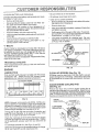
WARNING: This unit is equipped with an internal combustion engine and should not be used on or near any unimproved forest-covered, brush-covered or grass-covered
land unless the engine's exhaust system is equipped with
a spark arrester meeting applicable local or state laws (if
any), If a spark arrester is used it should be maintained tn
effect ve work ng order by the operator
In the state of California the above is required by law
(Section 4442 of the California Public Resources Code)
,Other states may have similar law& Federallawsapplyon
reaeral lanas, A spark arrester for the muffler is available
through your nearest Sears Authorized Service Center
(See REPAIR PARTS section of this manual),
LBM TEDTWO YEAR WARRANTY ON ELECTRgC START R DING EQUnPMENT
For two (2) years from the date of purchase, if this riding equipment is maintained, lubricated and tuned up according to the
instructionsin the owner's manual, Sears will repair or replace, free of charge, any parts found to be defective in material or
workmanship.,
This Warranty does not cover:
.
°
.
°
Expendable items which become worn during normal use, such as blades, spark plugs, air cleaners and belts.
Tire replacement or repair caused by puncturesfrom outside objects, such as nails, thorns, stumps, or glass.
Repairs necessary because of operator abuse, negligence, improper storage or accident or the failure to maintain the
equipment according to the instructions contained in the owner's manual.
Riding equipment used for commercial or rental purpose&
LnMITED 90 DAY WARRANTY ON BATTERY
For 90 days from date of purchase, if any battery included with this riding equipment proves defective in material or workmanship
and our testing determines the battery will not hold a charge, Sears will replace the battery at no charge_
WARRANTY SERVICE IS AVAILABLE BY RETURNING THE RIDING EQUIPMENT TO THE NEAREST SEARS SERVICE
CENTER/DEPARTMENT IN THE UNITED STATES,
This Warranty gives you specific legal rights, and you may also have other rights which may vary from state to state.
Sears,
Roebuck
and Co., Hoffman
3
Estates,
BL 60179 U.S.A.
TABLE
OF CONTENTS
OPERATION ...........................................................
11-14
MAINTENANCE SCHEDULE ...................................... 15
SERVICE AND ADJUSTMENT .............. ................ 19-26
STORAGE ....................................................................
27
TROUBLE SHOOTING ........................................... 28-29
REPAIR PARTS-TRACTOR ................................... 32-51
SLOPE SHEET ..................................................
;......... 65
SAFETY RULES ............................................................
2
PRODUCT SPECIFICATIONS ....................................... 3
DUSTOMER RESPONSIBILITIES
...................... 3,16-18
WARRANTY ...................................................................
3
TABLE OF CONTENTS .................................................
4
INDEX .............................................................................
4
ASSEMBLY ..............................................................
7-10
HNDEX
A
Adjustments:
Brake ........................................ 21
Carburetor ............................... 26
Choke ........................................ 25
Mower:
Front-To-Back .................... 20
Side-To-Side ...................... 19
Mower Belt .............................. 20
Throttle Control Cable ............. 25
Air Filter, Engine ............................ 18
Air, Screen, Engine ........................ 17
Assembly ..................................... 7-10
B
Battery:
Charging ........................................ 8
Cleaning ................................... 17
Installation ................................. 10
Levels ................................... 8,16
Preparation ................................ 8
Starting with Weak Battery ...... 24
Storage .................................... 27
Terminals ................................ 17
Belt:
Motion Drive:
Removal/Replacement ....... 22
Mower Blade Drive:
Removal/Replacement ....... 22
Mower Drive:
Adjustment ......................... 20
Removal/Replacement ....... 20
Blade:
Replacement ........................... 16
Sharpening ............................. 16
Brake Adjustment .......................... 21
C
Darburetor, Adjustment ................. 26
Choke, Adjustment ........................ 25
Controls, Tractor ............................ 11
Customer Responsibilities ........ 15-17
Engine:
Air Filter .............................. 18
Foam Pr e-Cleaner ........... 18
Air Screen, Engine .............. 17
Battery ................................. 16
Cooling Fins, Engine ........... 17
Engine Oil .............................. 17
Fuel Filter ..........................
18
Spark Plugs .......................... !8
Tractor:
Blade ................................... 16
Lubrication Chart ................ 15
Maintenance Schedule ........ 15
Tire Care .................... 8,16,23
Transaxle ............................. 23
Cutting Level, Mower ..................... 12
E
Engine:
Adjustments:
Carburetor ........................... 26
Choke ................................... 25
Throttle Control Cable ......... 25
Air Filter ................................... 18
Air Screen ................................. 17
Cooling Fins ............................ 17
Oil Change .............................. 17
Oil Level ............................. 13,17
Oil Type .................................... 17
Preparation .............................. 13
Starting .................................... 14
Storage ................................
27
F
Filter:
Air Cleaner. ..............................
Fuel .........................................
Fuel:
Storage ..................................
Type ........................................
Fuse ............................................
18
18
27
14
23
H
Hood Removal ..............................
24
L
Leveling Mower Deck .............. 19-20
Lubrication Chart ........................... 15
M
Maintenance Schedule .................. 15
Mower:
Adjustment:
Front-To-Back .................. 20
Side-To-Side .................... 19
Blade Replacement ................. 16
Blade Sharpening ................... 16
Cutting Level .......................... 12
Drive Belt Adjustment ............. 20
Insta,llation ................................... 9
Operation ................................
Removal ..................................
Mowing Tips ..................................
Muffler .............................................
Spark Attester ..........................
13
19
14
18
3
O
Oil:
Cold Weather Conditions .,. 13,17
Engine ..................................... 17
Operating Mower. .......................... 13
Operation .................................. 11-14
.p
Par king Brake ........................... 11,12
Parts Bag ........................................
6
Product Specifications ..................... 3
S
Safety Rules ................................... 2
Schematic ...................................... 31
Seat .................................................
8
Service & Adjustments ............. 19-26
Fuse ......................................... 23
Mower Adjustment
Front-To-Back ................... 20
Side-To-Side ..................... 19
Motion Drive Belt:
Removal/Replacement ...... 22
Mower Blade Drive Belt:
Removal/Replacement ...... 22
Mower Drive Belt:
Adjustment ........................ 20
Removal/Replacement ...... 21
Mower Removal ...................... 19
Tire Care ......................... 8,16,23
Slope Guide Sheet ........................ 65
Spark Plugs ................................... 18
Specifications .................................. 3
Starting the Engine ........................ 14
Steer ing Wheel ............................ 7,23
Stopping the Tractor ...................... 12
Storage ......... _................................ 27
T
Throttle Control Cable:
Adjustment .............................. 25
Tires ......................................
8,16,23
Transaxle, Maintenance ................ 23
Troubleshooting ........................ 28-29
W
Wiring Schematic ........................... 31
4
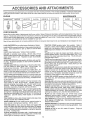
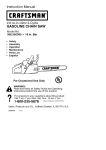
ACCESSORIES
AND ATTACHMENTS
These accessories and attachments were available when the unit was purchased. They are also available at most Sears retail outlets,
catalog and service centers Most Sears stores can order these items for you when you provide the model number of your tractor.
ENGINE
SPARK PLUG
MAINTENANCE
MUFFLER
AIR FILTER
GAS CAN
ENGINE OIL
STABILIZER
BLADES
BELTS
PERFORMANCE
Sears offers a wide variety of attachments that fit your vehicie. Many of these are listed below with brief explanations of how they can
help you, This list was cunent at the time of publication; however, it may change in future years - more attachments may be added, changes
may be made in these attachments, or some may no longer be available or fit your model. Contact your nearest Sears store for the
accessories and attachments
that are available for your unit,
Most of these attachments
do not require additional hitches or conversion kits (those that do are indicated) and are designed for easy
TRACTOR COVER protects tractor from weather
Made of
Evolution 3 fabric (water-repellent, extremely breathable, light
weight, soft, non-abrasive, pliable in all temperatures, durable,
stain/tear/puncture resistant, will not shrink or stretch) (Catalog
only.)
TILLER has 8 hp engine to prepare seed beds, cultivate, and
compost garden residue_ Chain-drive transmission. Six 11-inch
diameter one piece heat-treated steel tines Tills 30-inch path.
(Requires sleeve hitch.)
LAWN SWEEPERS let you collect grass clippings and leaves.
LAWN VACS for powerful collection of heavy grass clippings and
leaves. Wand attachment to pick up debris in hardqo-reach
places,
CARTS make hauling easy. Variety of sizes available.
ROLLER for smoother lawn surface.
36-inch wide, 18-inch
diameterwater-tight drum holds up to 390 Ibs. of weight. Rounded
edges prevent harm to tuff. Adjustable scraper automatically
cleans drum.
TILLER has 5 hp engine and 36-inch swath to prepare seed beds,
cultivate, and compost garden residue. Tiller has its own built-in
lift and depth control system and does NOT require a sleeve hitch,
Fits any lawn, yard, or garden tractor, Simply hook up to the
tractor drawbar and go!
DOZER BLADE removes snow; grades dirt, sand and gravel. 48
inches wide, 17 inches high, clears 44-inch path when angled
Master lift control lever for operator ease, Spring trip for snow
removal on uneven pavement; built-in float for blade to follow
ground contour, Reversible, replaceable scraper bar. (Use with
tire chains, wheel weights or rear drawbar weight)
SPREADER/SEEDERS
make seeding, fertilizing, and weed killing easy. Broadcast spreaders are also useful for granular deicers and san&
CORING AERATOR takes small plugs out of soil to allow moisture and nutrients to reach grass roots, 36-inch swath
24
hardened steel coring tips, 150 lb. capacity weight tray.
AERATOR promotes deep root growth for a healthy lawn. Tapered 2 5-inch steel spikes mounted on 10-inch diameter discs
puncture holes in soil at close intervals to let moisture soak in.
MULCH RAKE/DETHATCHER
loosens soil and flips thatch and
matted leaves to lawn surface for easy pickup. Twenty spring tine
teeth, Useful to prepare bare areas for seeding, Available for front
or rear mounting
SPRAYERS use 12ovolt DC electric motor that connects to the
tractor battery or other 12-volt source,
Includes booms for
automatic spraying when pulling, and hand held wand for spot
spraying.
Wand has adjustable spray pattern. For applying
herbicides, insecticides, fungicides, and liquid fertilizers.
sNOWTHROWER has 40-inch swath. Drum-type auger handles
powdery and wetJheavy snow. Mounts easily with simple pin
arrangemenL Discharge chute adjusts from tractor seat, 6-inch
diameter spout discharges snow 10 to 50 feet, Lift controlled at
tractor seat. (Use with chains, wheel weights, or rear drawbar
weight,)
FRONT END LOADER system includes double wide rear tires,
rear weight box, and hydraulically operated 526 cu.ft, bucket.
(Catalog only.)
REAR BLADE is 42 inches wide and operated from driver's seat
Reversible steel blade can be angled at 30 degrees for grading.
Reverses for snow plowing. (Requires sleeve hitch.)
SLEEVE CULTIVATOR is 43 inches wide, Prepares ground for
seeding, helps weed control. Steel frame holds 5 adjustable
sweeps. Adjusts vertically, horizontally. (Requires sleeve hitch)
Optional accessory for cultivator: steel furrow opener for wider
openings for potatoes, corn, and other deep-seeded crops.
PLOW turns soil 6 inches deep, cuts 10qnch furrow, Crank
adjustment controls depth, 3-position yoke sets width, Heavy
steel landslide for straight furrowing. (Requires sleeve hitch )
TIRE CHAINS are heavy duty; closely spaced extra-large cross
links give smooth ride, outstanding traction.
WHEEL WEIGHTS for rear wheels provide needed traction for
snow removal or dozing heavy materials.
(55 lbs. each)
DISC HARROW has 2 gangs of 4 steal blades that angle from 10
to 20 degrees, 40 inches wide, Can hook 2 units in tandem.
(Requires sleeve hitch,)
WEIGHT BRACKET for drawbar for snow removal applications
Can be mounted on front of tractor for plowing applications. Uses
(1) 55 lb. weight
TRACTOR CAB has heavy duty vinyl fabric over tubular steel
frame, ABS plastic top; clear plastic windshield offers 360 degree
visibility. Hinged metal doors with catch. Keeps operator warm
and dry. Remove vinyl and windshields for use as sun protector
in summer. (Catalog only.)
Optional accessories
for tractor cab: tinted/tempered solid
safety glass windshield with hand operated wiper; 12-volt amber
caution light for mounting on cab top. (Catalog only.)
SLEEVE HITCH for use with master lift system.
couples/uncouples,
5
Single pin
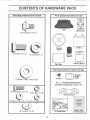
CONTENTS OF HARDWARE PACK
Parts Bag contents
shown
full size
Parts packed
separately
in carton
Seat
Battery aotd
(!) Shoulder Bolt 5/16-18
Battery
Steering
Wheel
(1)' Hex Bolt 1/2-13 x 1
(1) Lock Washer 1/2
Steertng
Sleeve
Owner's
Parts Bag
Parts bag contents
{_
G
"
full size
Wheel
Steering
Insert
(2) Keys
(1) Washer 17/32 x 1-3/16 x 12 Ga,
(2) Hex Bolts 1/4 - 20 x 3/4
not shown
Manual
II\/l\l\\\ll_\\lll\ll\l\\l\ll\\\\\ll\l\llll\/\\l_q
(2) Battery Carriage Bolts 1/4-20 x 7-1/2
@
(2) Hex Nuts 1/4 - 20
Terminal Guard
(2) Washers 9/32 x 5/8 x 16 Ga,(2) Lock Washers 1/4
=
........
(2) Wing Nuts 1/4 - 20
15 = Slope Sheet
6
J
Battery Caps
and Instructions
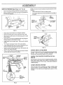
ASSEMBLY
i
Your new tractor has been assembled at the factory with exception of those parts left unassembled for shipping purposes.
To ensure safe and proper operation of your tractor, all parts and hardware you assemble must be tightened securely. Use
the correct tools as necessary to insure proper tightness.
TOOLS
REQUIRED
FOR ASSEMBLY
STEERING
WHEEL
A socket wrench set will make assembly easier. Standard
wrench sizes are listed,
(2) 7/16" wrenches
(1) Tire pressure gauge
(1) 3/4" wrench
(1) Utility knife
INSERT
I
HEXLOCKNUT
(1) Adjustable wrench
(_
When right and left hand is mentioned in this manual, it
means when you are in the operating position (seated
behind the steering wheel).
TO REMOVE
UNPACK
UNIT FROM CARTON
CARTON
Remove all accessible loose parts and parts cartons
from carton (See page 6).
Cut along lines on the carton, from top to bottom, a!l
four corners of carton and lay panels flat.
Remove mower deck from skid.
Check for any additional loose parts or cartons and
remove,
BEFORE
FLAT WASHER
ROLLING
STEERING SHAFT
STEERING
WHEEL
ADAPTER
_
...._
_
v_
UNIT OFF SKID
/
ATTACH
STEERING
WHEEL
(See Fig. 1)
Remove hex Iocknut and large flat washerfrom steep
ing shaft.
Position front wheels of the tractor so they are pointing
straight forward,
Slide steering sleeve over steering shaft_
Position steering wheel so cross bars are horizontal
(left to right) and slide onto adapter.
Secure steering wheel to steering shaft with hex locknut and large flat washer previously removed. Tighten
securely,
Snap insert into center of steering wheel.
Remove protective plastic from tractor hood and grill.
IMPORTANT: CHECK FOR AND REMOVEANYSTAPLES
IN SKID THAT MAY PUNCTURE TIRES WHERE UNIT IS
TO ROLL OFF SKID.
(See Fig, 2)
Raise attachment lift lever to its highest position.
Place gearshift lever in "NEUTRAL" position,
Release parking brake by depressing clutch/brake
pedal,
Roll unit backwards off skid.
/
STEERING
FIG. 1
CLUTCH/BRAKE
LIFT LEVER
PEDAL
]
PARKING
BRAKE
GEARSHIFT
LEVER
FIG. 2
7
SLEEVE
ASSEMBLY
HOW TO SET UP YOUR TRACTOR
INSTALL
PREPARE
Adjust seat before tightening adjustment bolt.
BATTERY
CAUTION:
&
(See
Fig. 3)
SEAT
(See
Fig. 4)
Remove cardboard packing on seat pan.
Wear eye and face shleld.
Place seat on pan and assemble shoulder bolt,
Wash hands or clothing immediately
if
accidentally In contact with battery acid.
Assemble adjustment bolt, lock washer and fiat washer
loosely, Do not tighten,
Do not smoke. Fumes from charged battery acid are explosive.
Tighten shoulder bolt securely,
Lower seat into operating position and sit on seat.
Read the instructions Included with the
battery vent caps. Always wear gloves,
clothing and goggles to protect your hands,
skin and eyes.
Slide seat until a comfortable position is reached which
allows you to press clutch/brake pedal all the way
down.
Get off seat without moving its adjusted position,
Your unit has a battery charging system which is sufficient
for normal use, However. periodic charging of the battery
with an automotive charger will extend its life,
See instructions packed with vent caps in parts bag.
Fill battery with acid. Fill each cell until it reaches the
bottom of the vent wells Do not overfill,
Allow battery to stand and settle for at least thirty
minutes After standing, check the level of acid, ff
below the vent wells, add more acid until the correct
level is reached.
Raise seat and tighten adjustment bolt securely,
SEAT
SEAT PAN
SHOULDER
BOLT
While battery is standing (after adding acid) and later while
battery is being charged, continue with assembly of uniL
IMPORTANT:
TO MAXIMIZE THE LIFE OF YOUR
BATTERY,
IT IS NECESSARY THAT THE BATTERY BE
CHARGED BEFORE USE.
FAILURE TO CHARGE
BATTERY CAN RESULT IN A SHORTENED BATTERY
LIFE
Charge battery at a rate of 6 amperes for 1 hour. Use
a 12 volt battery charger. Observe all safety precautions required for battery charging,
FLAT WASHER
ADJUSTMENT
COLT
Check the acid level after the battery is charged. If the
acid has fallen below the correct level, add distilled or
iron free water.
FIG. 4
CHECK
Install the vent caps to cover the vent wells. Wash the
top of the battery with water to remove any acid, then
wipe dry,
TIRE PRESSURE
The tires on your unit were overinflated at the factory for
shipping purposes. Correct tire pressure is important for
best cutting performance.
Check battery case for leakage to make sure that no
damage has occurred in handling.
Reduce tire pressure to PSI shown in "PRODUCT
SPECIFICATIONS" on page 3 of this manual.
Dispose of excess battery acid, Neutralize acid for
disposal by adding it to four inches of water in a five
gallon plastic containeL Stir with a wooden or plastic
paddle while adding baking soda until the addition of
more soda causes no more foaming.
Follow instructions on how to install battery.
VENT CAP
CUT AWAY VIEW
LOCK WASHER
VENT WELL
BATTERY
CELL ACID
LEVEL
FIG. 3
8
ASSEMBLY
Remove banding holding parallel link up against tractor.
NO'TE: Mower drive belt installation decal located on mower
housing,
Raise attachment lift lever to raise mower,
Remove retainer securing long hinge pin to parallel link
and remove hinge pin.
Turn height adjustment knob clockwise to the middle of
its travel.
INSTALL
MOWER
(See Figs.
5, 6, 7 & 8)
o
LIFT
LEVER
PLUNGER
o
HEIGHT
ADJUSTMENT
KNOB
MOWER
PARALLEL'
LINK
ATTACHMENT
LIFT LEVER
LONG
HINGE
PIN
FIG. 5
FIG, 7
Raise attachment lift lever to its highest position,
RAISE
Remove banding from mower deck links and V-belt,
Slide mower under tractor with discharge guard to right
side of tractor.
ADJUSTMENT
KNOB
Attach front of mower to parallel link with long hinge pin.
Secure hinge pin with retainer spring,
Install clutch rod in clutch lever, Secure with retainer
spring,
HEIGHT_
Turn height adjustment knob to its lowest setting,
Lower attachment lift lever to lower suspension arms,
Remove retainer springs from lift trunnions,
LOWER
FIG. 8
Slide trunnions through upper hole in lift brackets and
secure with retainer springs
CHECK
Pull LrH, idler pulley toward the right hand side of tractor
and rol! belt over mower drive pulley.
CLUTCH
LEVER
CHECK FOR PROPER POSITION OF ALL
BELTS
MOWER
ARMS
See the figures that are shown for replacingmotion, mower
drive, and mower blade drive belts in the Service and
Adjustments section of this manual. Verify that the belts are
routed correctly.
PULLEY
CHECK
LIFT
TRUNNION
BRAKE
SYSTEM
After you learn how to operate your tractor, check to see
that the brake is properly adjusted, See "TO ADJUST
BRAKE" in the Service and Adjustments section of this
manual
LONG
HINGE
PIN
RETAINER
LIFT
BRACKET
(USE UPPER
HOLES)
FIG. 6
LEVELNESS
For best cutting results, mower housing should be properly
leveled. See "TO LEVEL MOWER HOUSING" in the
Service and Adjustments section of his manual.
RETAINER
SPRINGS
CLUTCH
ROD
DECK
9
ASSEMBLY
INSTALL
&
BATTERY
(See Figs. 9 and 10)
CAUTION: Do not short batterytermlnals,
Before installing battery, remove metal
bracelets, wristwatch bands, rings, etc.
AIR
DUCT'
Positive terminal must be connected first
to prevent sparking
from accidental
grounding.
Raise hood,
Lift out air intake duct,
Make sure drain tube isfastened to drain hole in battery
tray and battery tray is positioned in hole of battery
support.
BATTERY TRAY
LIP
Place battery in plastic tray, battery terminals to front of
tracton
FIG. f()
First connect RED battery cable to positive (+) battery
terminal with hex bolt, flat washer, lock washer and hex
nut as shown. Tighten securely.
/CHECKLIST
BEFORE YOU OPERATE AND ENJOY YOUR NEW
TRACTOR, WE WISH TO ASSURE THAT YOU RECEIVE
THE BEST PERFORMANCEAND SA TISFACTION FROM
THIS QUALITY PRODUCT.
Connect BLACK grounding cable to negative (-) battery
terminal with remaining hex bolt, flat washer, lock washer
and hex nut. Tighten securely.
Slide the two battery bolts through the terminal guard
and start the wing nuts onto the threads.
PLEASE REVIEW THE FOLLOWING
Position terminal guard over the battery as shown, lower
bolts into key holes and slide square shafts of bolts into
slots of key holes.
Tighten wing nuts by hand making sure battery bolts
remain in slots of the key holes in the battery support.
Replace air intake duct. Air duct should be placed so
that the bottom edge is between the lip of the battery tray
and the battery.
Be sure terminal access doors are close&
,/
All assembly instructions have been completed,
,/"
No remaining loose parts in carton.
/
Batteryis properly prepared and charged,
hour at 6 amps),
/
Seat is adjusted comfortably and tightened securely,
/
All tires are properly inflated. (For shipping purposes,
the tires were overinflated at the factory).
/
Be sure mower deck is properly leveled side-to-side/
front-to-rear for best cutting results. (Tires must be
properly inflated for leveling).
/
Check mower and drive belts. Be sure they are routed
properly around pulleys and inside all belt keepers.
v"
Check wiring. See that all connections are still secure
and wires are properly clampe&
Use terminal access doors for:
inspection for secure connections (totighten hardware).
Inspection for corrosion.
Testing battery.
CHECKLIST:
Jumping (if required).
(Minimum 1
WHILE LEARNING HOW TO USE YOUR TRACTOR, PAY
EXTRA A TTENTION TO THE FOLLOWING IMPORTANT
ITEMS:
Periodic charging
LOCK
WASHER
/
Engine oil is at proper level,
/
Fuel tank is filled with fresh, clean, regular unleaded
gasoline.
Become familiar with all controls-their location and
function. Operate them before you start the engine.
/
HID( NUT
v"
HEX
BOLT
NEGATIVE
(BLAC_
CABLE
FIG. 9
10
Be sure brake system is in safe operating condition,
OPERATION
KNOW YOUR TRACTOR
READ THIS OWNER'S
MANUAL
AND SAFETY
RULES
BEFORE
OPERATING
YOUR TRACTOR.
Compare the illustrations with your Tractor to familiarize yourself witl_ the location of various controls and adjustments, Save
this manual for future reference.
ATTACHMENT
CLUTCH
LEVER
LIFT LEVER PLUNGER
LIGH"
MENT LIFT LEVER
CI"
CLUTCH/BRAKE
PEDAL
THROTTLE
CONTROL
PARKING BRAKE
LEVER
HEIGHT/
KNOB
--'--------GEARSHIFT LEVER
FIG. 11
Sears
tractors
conform
to the safety
standards
of the American
National
Standards
Institute.
GEARSHIFT LEVER ,. Selects the speed and direction of
the tractor.
IGNITION SWITCH - Used to start and stop the engine,
LIGHT SWITCH - Turns the headlights on and off.
PARKING BRAKE LEVER - Locks clutch/brake pedal into
the brake position.
THROTTLE CONTROL - Used to control engine speed.
CHOKE CONTROL - Used when starting a cold engine,
ATTACH MENT CLUTCH LEVER - Usedto engage mower
blades or other attachments mounted to your tractor,
ATTACHMENT LIFT LEVER - Used to raise and lower
mower deck or other attachments mounted to your tractor.
CLUTCH/BRAKE
PEDAL - Used for declutching and
braking the tractor and starting the engine,
HEIGHTADJUSTMENT
KNOB- Usedto adjustthe mower
height
LIFT LEVER PLUNGER - Used to release attachment lift
lever when changing its position,
11
OPERATION
The operation of any tractor can result in foreign objects thrown into the eyes, which can resu t
In severe eye damage. Always wear safety glasses or eye shields before starting your tractor
and while movlng. We recommend wide vision safety mask for over the spectacles or standard
I
safety glasses.
HOW TO USE YOUR TRACTOR
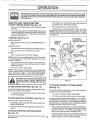
TO SET
PARKING
BRAKE
(See
Fig.
Start tractor with clutch/brake pedal depressed and
gearshift lever in "NEUTRAL" position.
12)
Move gearshift lever to desired positiom
Depress clutch/brake pedal into full "BRAKE" position
and hold,
Slowly release clutch/brake pedal to start movement,
IMPORTANT: BRING TRACTOR TO A COMPLETE STOP
BEFORE SHIFTING OR CHANGING GEARS. FAILURE
TO DO SOWILLSHORTENTHEUSEFULLIFEOFYOUR
TRANSAXLE,
Place parking brake lever in "ENGAGED" position and
release pressure from clutch/brake pedal Pedal should
remain in "BRAKE" position. Make sure parking brake
will hold vehicle secure.
STOPPING
(See
Fig,
12)
A3TACHMENT
CLUTCH LEVER
"ENGAGED"POSITION
MOWER BLADES Move attachment clutch lever to "DISENGAGED"
sition,
THRO'I-rLE
CONTROL
LEVER
po-
"DISENGAGED"
POSITION
GROUNDDRIVEo
CHOKE
CONTROL
Depress clutch/brake pedal into full "BRAKE" position_
Move gearshift lever to "NEUTRAL" position.
ENGINE -
IGNITION
KEY
Move Throttle Control to "SLOW"position,
"BRAKE"
POSITION
NOTE: Failure to move throttle control to "SLOW" position
and allowing engine to idle before stopping may cause
engine to "backfire".
Turn ignition key to "OFF" position and remove key.
Always remove key when leaving vehicle to prevent
unauthorized use.
Never use choke to stop engine.
NOTE: Under certain conditions when unit is standing idle
with the engine running, hot engine exhaust gasses may
cause "browning" of grass. To eliminate this possibility,
always stop engine when stopping unit on grass areas.
POSITION
CLUTCH/BRAKE
PEDAL"DRIVE"
POSITION
described
above, before leaving thel
CAUTION; Always stop unit completely, as i
eOperator's position; to empty grass catcher, I
I_
FIG. 12
TO ADJUST
TO USE
CHOKE
CONTROL
HEIGHT
ADJUSTMENT
KNOB
(See Fig. 12)
MOWER
CUTTING
(See Fig. 12)
Use choke control when everyou are starting a cold engine.
Do not use to start a warm engine_
The cutting height is controlled by turning the height adjustment knob in desired direction_
To engage choke control, pull knob ouL Slowly push
knob in to disengage.
Turn knob clockwise to raise cutting height.
Turn knob counterclockwise
TO USE
THROTTLE
CONTROL
(See
Fig.
12)
Operating engine at less than full throttle reduces the
battery charging rate.
Full throttle offers the best bagging and mower' performance.
FORWARD
AND
The average lawn should be cut to approximately 2-1/
2 inches during the cool season and 10 over 3 inches
during hot months. For healthier and better looking
lawns, mow often and after moderate growth.
BACKWARD
(See Fig. 12)
The direction and speed of movement is controlled by the
gearshift lever.
to lower cutting height.
The cutting height range is approximately 1_1/4" to 3-3/4".
The heights are measured from the ground to the blade tip
with the engine not running. These heights are approximate and may vary depending upon soil conditions, height
of grass and types of grass being mowed,
Always operate engine at full throttle.
TO MOVE
HEIGHT
12
For best cutting performance, grass over 6 inches in
height should be mowed twice, Make the first cut
relatively high; the second to desired height.
I
OPERATION
TO OPERATE
MOWER
TO OPERATE
(See Fig. 12)
Your unit is equipped with an operator presence sensing
switch Any attempt by the operator to leave the seat with
the engine running and the mower clutch engaged will shut
off the engine.
F-_
J _
I _
ON HILLS
CAI.JTION:Do
not drive up or down
hills with slopes greater than 15 and
do not drive across any slope.
Select desired height of cut, using height adjustment
knob,
Choose the slowest speed before starting up or down
hills,
Lower mower with lift lever.
Avoid stopping or changing speed on His,
Engage mower by slowly moving mower clutch lever to
"ENGAGED" position,
TO STOP MOWER - Move mower clutch lever to
"DISENGAGED" position
If slowing is necessary, move throttle control lever to
sDwer position
If stopping is absolutely necessary, push clutch/brake
pedal quickly to brake position and engage parking
brake,
Move gearshift
without either the entire grass catcher,
on mowers so equipped, or the disAUTION:
operate the mower
charge
guardDo innot
place,
I&
m,
lever to "NEUTRAL"
position
To restart rnovement, move gearshift lever to 1st gear
Be sure you ha_/e allowed room for unit to roll slightly as
you restart movement,
,i
Slowly release parking brake and clutch/brake pedal,
Make all turns slowly,
TO TRANSPORT
_,
Raise attachment lift control to highest position,
R.H.
RUNNER
When pushing or towing your unit. be sure gearshift
lever is in "NEUTRAL" position_
Do not push unit at more than five (5) MPH.
BEFORE
.DfSCHARGE
GUARD
CHECK
STARTING
ENGINE
THE ENGINE
OIL LEVEL
(See Fig. 14)
The engine in your unit has been shipped, from the
factory, aiready filled with summer weight oil.
F]G, 13
Check engine oil with unit on level ground,
Remove dipstick and wipe clean, replace, wait for a few
seconds, remove and read oil level If necessary, add
oil until "FULL" mark on dipstick is reached, Do not
overfill.
For cold weather operation you should change oil for
easier starting (see "OIL VISCOSITY CHART" in the
Maintenance section of this manual),
To change engine oil, see the Maintenance section in
this manual,
ENGINE OIL
FILLER CAP
AND DIPSTICK
FIG. 14
13
OPERATION
MOWING TIPS
ADD GASOLINE
Tire chains cannot be used when the mower housing
is attached to unit.
Fill fuel tank
Use fresh, clean, regular unleaded
gasoline (Use of leaded gasoline will increase carbon
and lead oxide deposits and reduce valve life)
iMPORTANT: WHEN OPERATING IN TEMPERATURES
BELOW 32"F 0°C), USE FRESH, CLEAN WINTER GRADE
GASOLINE TO HELP NSURE GOOD COLD WEATHER
STARTING
WARNING:
Experience indicates that alcohol blended
fuels (called gasohol or using ethanol or' methanol) can
attract moisture which leads to separation and formation of
acids during storage
Acidic gas can damage the fuel
system of an engine while in storage
To avoid engine
problems, the fuel system should be emptied before storage of 30 days or longer. Drain the gas tank, start the
engine and let it run until the fuel lines and carburetor are
empty. Use fresh fuel next season See Storage Instructions for additional information.
Never use engine or
carburetor cleaner products in the fuel tank or permanent
damage may occur
Mower should be properly leveled for best mowing
performance. See TO LEVEL MOWER HOUSING"
in the Service and Adjustments
section of this
manual,
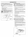
Use the runner on the right hand side of mower as
a guide. The blade cuts approximately an inch outside the runner (See Fig. 13).
The left hand side of mower should be used for trimruing
Drive so that clippings are discharged onto the area
that has been cut, Have the cut area to the right of
the machine. This will result in a more even distribution of clippings and more uniform cutting,
!
CAUTION;
Fill to bottom of gas tank
filler neck° Do net overfill. Wipe off any
spilled oil or fuel. Do not store, spill or
use gasoline near an open flame.
TO
START
ENGINE
(See
Fig.
I
!
When mowing large areas, start by turning to the
right so that clippings will discharge away from
shrubs, fences, driveways, etc. After' one or two
rounds, mow in the opposite direction making left
hand turns until finished (See Fig, 15).
f
12)
When starting engine for the first time or if engine has
run out of fuel, it will take extra cranking time to move
fuel from the tank to the engine.
Depress the clutch/brake
brake,
Place gearshift
pedal and set the parking
lever in "NEUTRAU'
position
Move attachment clutch to "DISENGAGED"
position.
FIG_ 15
Pull choke control out to "CHOKE" position for cold
engine start.
For warm engine start do not use
choke control.
If grass is extremely tall, it should be mowed twice
to reduce load and possible fire hazard from dried
clippings, Make first cut relatively high; the second
to the desired heighL
Move throttle control to midway between "FAST" and
"SLOW" positions.
Turn ignition key clockwise to "START" position and
release key as soon as engine starts. Do not run
starter continuously for' more than fifteen seconds
per minute.
If engine does not start after several
attempts, move throttle control to "FAST" position,
wait a few minutes and try again.
Do not mow grass when it is weL
plug mower and leave undesirable
grass to dry before mowing,
Always operate engine at full throttle when mowing
to assure better mowing performance and proper
discharge of material,
Regulate ground speed by
selecting a low enough gear to give the mower cutting performance as well as the quality of cut desired.
When engine starts, slowly push choke control in.
Move throttle control to "FAST" position
Allow engine to warm up for a few minutes before
engaging clutch/brake pedal or attachment clutch
switch.
When operating attachments, select a ground speed
that will suit the terrain and give best performance of
the attachment being used,
NOTE: If at a high altitude (above 3000 feeti or in cold
temperatures (below 32 F), the carburetor fuel mixture
may need to be adjusted for best engine performance.
See "TO ADJUST CARBURETOR" in the Service and
Adjustments section of this manual.
arm_.L_
_
armmCAUTION:
Before driving the tractor,
install mower or remove front mower
suspension
bracket and suspension
I
I
I
I
Wet grass will
clumps, Allow
14
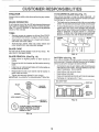
CUSTOMER
MAINTENANCE
SCHEDULE
_e/
FILL IN DATES
AS YOU COMPLETE
T
_'_
/_'_
Check
Brake
Check
Tire Pressure
Checkfor
BSPONS BnL TBBS
_O/Z_OZ_9,0_:
_
"_/_?,q._'_/_£:k'_/_;
Operation
Loose
Iv'
e/
Fasteners
Sharpen/Replace
Lubrication
Chart
Mower
Blades
T
Check
Battery
0
Clean
Battery
R
Check
Transmission
Coollng
Adjust
Blade
Tension
Adjust
Motion
Drive Belt(s)
Check
Engine
Oil Level
Level/Recharge
and Terminals
Belt(s)
m
J
e,"
v'
Tension
,
Change
E
N
Engine
Clean
,t
,
,
,
Oil
Air Filter
Clean Air Screen
G
Inspect
|
Replace
Muffler/Spark
N
Clean
Oil Filter
Arrester
(If equipped)
eng'oe
cooling
V'2
V'V'
Fins
Replace
Spark
Plug
Replace
Air Filter Paper
Replace
Fuel Filter
Cartridge
,v'e v'
1 - Change more often when operating under a heavy load or In high ambient temperatures
2 - Service more often when operating in dirty or dusty conditions
GENERAL
3 - If equtpped with ott filler, change oi! every 50 hours
4 - Replace blades more often when mowing tn sandy soil
5 If equipped with adjustable system
LUBRICATION
RECOMIVtENDATIONS
CHART
The warranty on this tractor does not cover items that have
been subjected to operator abuse or negligence.
To
receive ful! value from the warranty, operator must maintain
tractor as instructed in this manual,
@
BEARING
Some adjustments will need to be made periodically to
properly maintain your tractor,
"FRONT WHEEL@
BEARING ZERK
ZERK
All adjustments in the Service and Adjustments section of
this manual should be checked at least once each season,
Once a year you should replace the spark plug, clean
or replace air filter, and check blades and belts for
wear, A new spark plug and clean air filter assure
proper air4uel mixture and help your engine run better
and last longer,
BEFORE
EACH
(_)ATTAOHMENT"
CLUTCH
PIVOT(S)
USE
PIVOTS
Check engine oil level
Check brake operation,
(_) SAE 30 OR 10W30 MOTOR OIL API - SG
Check tire pressure,
Check for loose fasteners
@ GENERAL
PURPOSE
GREASE
@ REFER TO CUSTOMER
15
RESPONSIBILITIES
"ENGINE"
SECTION
IMPORTANT:
OO NOT OIL OR GREASE
THE PIVOT POINTS
WHICH HAVE SPECIAL NYLON BEARINGS
VISCOUS
LUBRICANTS WILL ATTRACT
DUST AND DiRT THAT WILL SHORTEN
THE LIFE OF THE SELF-LUBRICATING
BEARINGS,
IF YOU
FEEL THEY MUST BE LUBRICATED,
USE ONLY A DRY, POWDEREO GRAPHITE
TYPE LUBRICANT
SPARINGLY
CUSTOM
RESPONSHB LmE$
TRACTOR
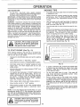
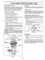
TO SHARPEN
BLADE
(See Fig. 17)
Care should be taken to keep the blade balanced, An
unbalanced blade will cause excessive vibration and eventual damage to mower and engine.
Always observe safety rules When performing any maintenance.
BRAKE
OPERATION
The blade can be sharpened with afile or on a grinding
wheel, Do not attempt to sharpen while on the mower,
To check blade balance, drive a nail into a beam or wall,
Leave about one inch of the straight nail exposed.
Place center hole of blade over the head of the nail. If
blade is balanced, it should remain in a horizontal
position. If either end of the blade moves downward,
sharpen the heavy end until the blade is balanced,
If unit requires more than six (6) feet stopping distance at
high speed in hiahest gear, than brake must be ad usted
(See "TO ADJUST BRAKE n Servce and Adjustments
section of this manual)
TIRES
Maintainproper air pressure in all tires (See "PRODUCT SPECIFICATIONS
on page 3 of this manual),
CENTER
HOLE
Keep tires free of gasoline, oil. or insect control chemicals which can harm rubber.
Avoid stumps, stones, deep ruts, sharp objects and
other hazards that may cause tire damage.
BLADE
O
CARE
For best results mower blades must be kept sharp,
place bent or damaged blades.
ReFIG. 17
BLADE
REMOVAL
(See Fig. 16)
Raise mower to highest position to allow access to
blades
BATTERY
(See Fig. 18)
Your unit has a battery charging system which is sufficient
for normal use, However, periodic charging of the battery
with an automotive charger will extend it's life.
Remove hex bolt, lock washer and flat washer securing
blade.
Install new or resharpened
towards deck as shown
Acid solution level in each battery cell should be even
with bottoms of vent wells. Add only distilled or iron free
water if necessary. Do not overfill
blade with trailing edge up
Reassemble hex bolt. lock washer and flat washer in
exact order as shown.
Keep battery and terminals clean.
Keep battery bolts tight.
Keep vent caps tight and small vent holes in caps open,
Recharge at 6 amperes for 1 hour.
Tighten bolt securely (30-35 Ft Lbs. torque).
IMPORTANT: BLADE BOLT IS GRADE 5 HEAT TREATED.
CUT AWAY VIEW
I,
BLADE
MANDREL
._.
VENT CAP
-- JVENT
--
WASHER
_WELL
--"
LEVEL
LOCK WASHER _
©
FIG. 18
-IEX BOLT
(GRADE 5)*
*A GRADE S HEAT TREATED BOLT
CAN BE IDENTIFIED
BYTHREE
LINES ON THE BOLT HEAD AS
SHOWN AT LEFT.
FIG. 16
16
_,=,l
CUSTOMER RESPONS B LITHES
TO CLEAN BATTERY AND TERMINALS -
, Be sure vehicle is on level surface
Corrosion and dirt on the battery and terminals can cause
the battery to "leak" power,
Remove terminal guard
Disconnect BLACK battery cable first then RED battery cable and remove battery from tractor
Wash battery with solution of four tablespoons of
baking soda to one gallon of water. Be careful not to get
the soda solution into the cells
• Oil will drain more freely when warm,
. Catch oil in a suitable container,
Remove oil filler cap, Be careful notto allow dirtto enter
the engine when changing oil
Remove drain plug
After oil has drained completely, replace oil drain plug
and tighten securely,
Rinse the battery with plain water and dry.
Clean terminals and battery cable ends with wire brush
until bright
Coat terminals with grease or petioleum jelly
Refillenginewithoilthroughoilfillertube
Pourslowly.
Do not overfill. For approximate capacity see "Product
Specifications" on page 3 of this manual
Use gauge on dipstick for checking level.
dipstick is in all the way for accurate reading
at "FULL" line on dipstick
Reinstall battery (See "INSTALL BATTERY" in Assembly section of this manual)
Be sure
Keep oil
V- BELTS
Check V-Belts for deterioration and wear after 100 hours
and replace if necessary, The mower blade drive belt can
be adiusted to provide you with longer belt life (See "TO
ADJUST MOWER BLADE DRIVE BELT' in the Service
and Adjustments section of this manual),
The motion drive belt is not adjustable Replace belts ifthey
begin to slip from wear,
TRANSAXLE
ENGINE OIL DIPSTICK
AND FILL TUBE
OIL DRAIN PLUG
COOLING
Keep transaxle free from build-up of dirt and chaff which
can restrict cooling,
FIG. 20
ENGINE
LUBRICATION
Only use high quality detergent oil rated with API service
classification SG, Select the oil's SAE viscosity grade
according to your expected operating temperature,
CLEAN
AIR SCREEN
(See Fig. 19)
Air screen must be kept free of dirt and chaff to prevent
engine damage from overheating, Clean with a wire brush
or compressed airto remove dirt and stubborn dried gum
fibers,
SAE VISCOSITY GRADES
CLEAN
(See
_F
.20'
°c .;o.
O'
30'
._o" .1_'
32'
40"
_°
TEMPERATURE RANGE ANTICIPATED
60"
1_'
80"
_0'
COOLING
FINS
Fig. 21)
Remove any dust, dirt or oil from engine cooling fins to
prevent engine damage from overheating, Engine blower
housing must be removed. Remove side panels and hood
(Sea"TO REMOVE HOODAND GRILLASSEMBLY"in
the
Service and Adjustments section of this manual.)
100'
;0"
ENGINE
4_"
BEFORE NEXT OIL CHANGE
FIG. 19
TOP AIR
NOTE: Although multi-viscosity oils (5W30, 10W30, etc.)
improve starting in cold weather, these mufti-viscosity oils
will result in increased oil consumption when used above
32°F, Check your engine oil level more frequently to avoid
possible engine damage from running low on oil.
GUIDE COVER
_,
°
CLEAN ENGINE
COOLING
"_'
FINS
Change the oil after the first two hours of operation and
every 25 hours thereafter or at least once a year if the
tractor is not used for 25 hours in one year
Check the crankcase oil level before starting the engine
and after each eight (8) hours of continuous use, Tighten
oil fill cap/dipstick securely each time you check the oil
level
TO CHANGE ENGINE OIL (See Figs 19 and 20)
Determine temperature range expected before oil change
All oil must meet API service classification SG
MUFFLER
AIR GUIDE
COVER (BOTH SIDES)
17
FIG. 21
CUSTOMER RESPONSmlBUL TIES
AIR
FILTER
(See
Fig.
MUFFLER
22)
Your engine will not run properly using a dirty air filter.
Clean the foam pr e-cleaner element after every 25 hours of
operation or every season. Service paper cartridge every
100 hours or every season, whichever occurs firsL
Inspect and replace corroded muffler and spark arrester (if
equipped) as it could create a fire hazard and/or damage,
SPARKPLUGS
Service air cleaner more often under dusty conditions.
Replace spark plugs at the beginning of each mowing
season or after every 100 hours of use, whichever comes
first. Spark plug type and gap setting is shown in "PRODUCT SPECIFICATIONS
on page 3 of this manual.
Remove knob(s) and cover
TO SERVICE PRE-CLEANER
Slide foam pre-cleaner off cartridge.
Wash it in liquid detergent and water.
IN-LINE
FUEL FILTER
(See Fig. 23)
Fuel filter should be replaced once each season. If fuel filter
becomes clogged, obstructing fuel flow to carburetor replacement is required
Squeeze it dry in a clean cloth.
Saturate it in engine oil. Wrap it in clean, absorbent
cloth and squeeze to remove excess oil.
Reinstall pre-cleaner over qartridge.
With engine cool, remove filter and plug fuel line
sections.
Reinstall cover and secure with knob(s).
TO SERVICE CARTRIDGE
Place new fuel filter in position in fuel line with arrow
pointing towards carburetor.
Remove wing nuts and cartridge plate.
Be sure there are no fuel line leaks and clamps are
properly positioned.
Remove cartridge and clean by tapping gently on flat
surface.
Immediately wipe up any spilled gasoline.
If very dirty, replace or wash in a nonsudsing detergent
and warm water solution. Rinse thoroughly with water
from inside out until water runs clear. Let cartridge dry
thoroughly before using.
Reinstall cartridge plate, wing nuts, precleaner, cover
and secure with knob(s)
IMPORTANT:
PETROLEUM SOLVENTS, SUCH AS
KEROSENE, ARE NOT TO BE USED TO CLEAN THE
CARTRIDGE THEY MAY CAUSE DETERIORATION OF
THE CARTRIDGE
DO NOT OIL CARTRIDGE. DO NOT
USE PRESSURIZED
AIR TO CLEAN
OR DRY
CARTRIDGE
CLAMF
FIG. 23
CLEANING
KNOB _
..X3-
Clean engine, battery, seat, finish, etc. of all foreign
matter.
Keep finished surfaces and wheels free of all gasoline,
oil, etc.
Protect painted surfaces with automotive type wax.
We do not recommend using a garden hose to clean your
unit unless the electrical system, muffler, air filter and
carburetor are covered to keep water ouL Water in engine
can result in a shortened engine life.
FOAM
PRE_CLEANER
CARTRIDGE
AIR SCREEN
FIG, 22
18
SF=RVmCEAN
....
ADJUSTMENTS
i
_rrl
cAuTIoN:
BEFORE PERFORMING ANY SERVICE OR ADJUSTMENTS:
Depress clutch/brake pedal fully and set parking brake.
Place gearshift lever in NEUTRAL
position,
Place attachment clutch in "DISENGAGED"
position,
Turn ignition key "OFF" and remove key.
Make sure the blades and all moving parts have completely stopped.
Disconnect spark plug wire from spark plug and place wire where it cannot come in contact with
plug.
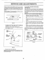
TRACTOR
SIDE-TO-SIDE
TO REMOVE
MOWER
Measure height from bottom deck curl to ground level at
front corners of mower
Distance "A" should be the
same.
Oc OM
Raise lift lever to raise suspension arms, Slide mower
out from under tractor,
GRO .OL,NE
IMPORTANT; IFANATTACHMENT OTHER THAN THE MOWER
DECK IS TO BE MOUNTED ON THE TRACTOR, REMOVE THE
L,H. AND RH, SUSPENSION
ARMS AND THE FRONT
SUSPENSION BRACKET.
CLUTCH
LEVER
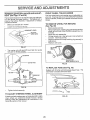
(See Figs. 25 and 26)
Raise attachment lift lever to its highest position.
(See Fig. 24)
Mower will be easier to remove from the right side of unit,
Remove mower drive belt from mower drive pulley only
(See "TO REPLACE MOWER DRIVE BELT" through
step removing belt from mower drive pulley)
Remove retainer spring from clutch rod. pull clutch red
out of clutch lever,
Pull retainer springs out of rear suspension trunnbns.
Remove rear suspension trunnions from lift bracketsr
Pull retainer springs from front hinge pins,
Remove hinge pins attaching parallel link to mower and
front axle,
CLUTCH
ROD
ADJUSTMENT
RETAINER
SPRINGS
FIG, 25
MOWER
DRIVE
PULLEY
If distance "A" needs to be changed, snap out access
hole cover on left side of tractor above footrest.
To raise left side of mower, loosen nut "B" and tighten
nut "C"
To lower left side of mower, loosen nut "C" and tighten
nut "B"
LIFT
TRUNNION
When distance "A" is equal, securely tighten nuts "B"
and "C"
SUSPENSION
LONG
HINGE PiN
NUT "0"
ARMS
SIDE TO SIDE
ADJUSTMENT
TRUNNION
RETAINER
SPRING
LIFT
BRACKET
F{G. 24
TO INSTALL
MOWER
See "INSTALL MOWER" in the Assembly section of this
manuat
FIG. 26
TO LEVEL
MOWER
HOUSING
Replace access hole cover,
Adjust the mower while tractor is parked on level ground or
driveway,
Make sure tires are properly inflated (See
"PRODUCT SPECIFICATIONS" on page 3) If tires are
over or underinfiated,
mower
you will not properly adjust your
19
SEIRVICIB AN
ADJUSTMENTS
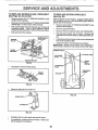
TO ADJUST
FRONT-TO-SACK ADJUSTMENT (See Figs, 27 and 28)
To obtain the best cutting results, the mower housing should
be ad usted so the back is approximately 7/8" to 1-1/8"
h gher than the front when the mower is in height adjustment
position.
MOWER
DRIVE
BELT
(See Fig. 29)
Your tractor has been manufactured with the ability to readjust mower drive belt to provide you with longer belt life.
If the attachment clutch lever travels forward in the slot
before spring tension resistance is evident, adjustment is
necessary,
IMPORTANT'; CHECK FOR PROPER SPRING TENSION WITH
ENGINE OFF AND LIFT LEVER IN HIGHEST POSITION,
Measure distance "D" from ground line to bottom of deck
curl at centerline outside of mandrels
Remove mower deck from tractor (See "TO REMOVE
MOWER" in this section of this manual)
BACK__
[
Remove cotter' pin from L.H. side of rock shaft assembly
__'_FRONT
I D + 7/8" TO ,-1/8"
Loosen the four Iocknuts on the RH. and L.H. pivot
brackets only until rock shaft assembly can be removed.
Dt
/////////////'///////////////////////////
Remove rock shaft assembly from pivot brackets.
Remove extension spring from lower hole (original
position) in rock shaft assembly and place in upper
hole.
FIG. 27
To raise rear of mower, loosen nut "E" on both rear
suspension arms. Screw both nuts "F" on both rear
suspension arms an equal number of turns,
Replace rock shaft assembly making sure carriage
bolts are seated in square holes of mower housing.
Replace cotter pin on L.H side of rock shaft assembly.
When distance "D" is 7/8" to 1-1/8" higher at rear than
front, retighten nuts "E".
NOTE: When instal!ing a new belt, extension spring must
be returned to lower hole (original position) on rock shaft
assembly.
REAR
SUSPENSION
ARM
UPPER
EXTENSION
HOLE
SPRING
_"---_
\
NUT "E"
REAR
SUSPENSION
TRUNNION
SHAFT
BRAKEROD _
ASSEMBLY
LIFT
BRACKET
_
(ORIGINAL PIVOT
.......
_
POSITION)
COITER/
PIN "
NUT "F"
._r_.
LOCKNUTB_
"
FIG. 29
FIG. 28
Recheck
._ROCK
side-to-side
adjustment.
IMPORTANT; WHEN ADJUSTING REAR SUSPENSION ARMS,
ALWAYS ADJUST BOTH EQUALLY SO MOWER WILL STAY
LEVEL SIDE-TO-SIDE,
2O
;iv%T
JZ
SERVICE AND ADJUSTMEHT$
TO REPLACE
30 and 31)
MOWER
DRIVE
BELT
(See Fig.
BELT GUIDES
Park the tractor on level surface. Engage perking brake.
BELT REMOVAL ,,
Place attachment clutch in "DISENGAGED" position.
•
o
Turn height adjustment knob to lowest setting.
Move attachment lift lever forward to lower mower to its
lowest position.
o
Roll belt off engine pulley.
o
Pull belt off mower pulley and both idler pulleys.
,,
Slide belt from under spring.
ENGINE PULLEY
SPRING
R.H. IDLER
PULLEY
LH. IDLE_
PULLEY
MOWER
PULLEY
NOTE: If necessary loosen guards and belt guides for ease
of belt removal and installation.
ATTACHMENT
LIFT LEVER
"HIGHEST"
POSITION
"LOWEST"
MOWER DRIVE BELT
FIG, 31
BELT INSTALLATION -
"ENGAGED"
:'OSITION
ATTACHMENT
3LUTCH
"DISENGAGED"
POSITION
o
Slidebelt underspring.
o
Place belt around mower pulley and both idler pulleys.
o
Roll belt over engine pulley
o
Make sure belt is in all pulley grooves and inside all belt
guides.
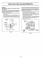
TO ADJUST
HEIGHT
ADJUSTMENT
BRAKE
(See
Fig.
32)
Your unit is equipped with an adjustable brake system
which is mounted on the right side of the transaxle.
KNOB
If unit requires more than six (6) feet stoppingdistance at
high speed in highest gear, then brake mustbe adjusted..
FIG, 30
°
DepressclutcWbrakepedaland
o
Measure distance between brake operating arm and
nut "A" on brake red.
°
If distance is other than 1-1/2", disengage parking
brake, loosen jam nut and turn nut "A" until distance
becomes 1-1/2". Retighten jam nut against nut"A".
°
Engage parking brake and recheck distance.
•
Road test unit for proper stopping distance as stated
above.. Read ust if necessary. If stopping distance is still
greater than s x (6) feet n h ghest gear, further maintenance is necessary. Contact your nearest authorized
service center.
BRAKE ARM
engage parking brake.
NUT "A"
JAM NUT
BRAKE
ARM
21
FIG. 32
SERVICE
TO REPLACE
MOWER
BLADE
ADJUSTMENTS
DRIVE
BELT
TO REPLACE
(See Fig. 36)
(See Figs. 33, 34 and 35)
',
Remove mower (See "TO REMOVE MOWER" in this
section of this manual).
o
Remove mower drive belt (See'3"O REPLACE MOWER
DRIVE BELT' in this section of this manual).
Pull mower blade drive belt towards rear of mower at
tensioning pulley. Place a block between tension
bracket and spring bracket. Roll belt off tension pulley_
°
o
DRIVE
BELT
Park thetractoron levelsurface Engage parkingbrake,
Forassistance,there is a belt installationguide decal on
bottomside of leftfootrest.
Roll belt off all other pulleys.
MOWER BLADE
DRIVE BELT
TENSION
MOTION
o
Remove mower (See "TO REMOVE MOWER" in this
section of this manuaL)
o
Remove upper belt keeper.
o
o
Remove belt from stationary idler and clutching idler.
Pull belt slack toward rear of tractor. Remove belt
upwards from transaxle pulley by deflecting belt keep..
erso
o
Pull belt toward front of tractor and ramove downwards
from around engine pulley°
o Install new belt by reversing above procedure.
IMPORTANT:
MAKE SURE UPPER BELT KEEPER IS
POSITIONED PROPERLY BETWEEN LOCATOR TABS_
SPRING
BRACKET
ENGINE PULLEY_..
,,. LOCATOR TABS
BLOCK
J
IDLER "--,.,--.._
TENSION BRACKET
CLUTCHING
FIG. 33
_UPPER
BELT
KEEPER
__
STA'NONARYI
IDLER
Use pliers to remove brake spring.
TRANSAXLE
PULLEY
BRAKE
SPRING
FIG. 34
•
Remove cotter pin from brake rod
FIG. 36
BRAKE ROD -'_
COTTER PIN
FIG. 35
•
Pull belt out from under brake rod and off mower.
•
To install belt. reverse above procedure.
belt is enga,ned in all pulleys.
Make sure
22
SERVICE AND ADJUSTMENTS
TRANSAXLE
MENT
SHIFTER
(See Figs.
LINKAGEANDADJUST-
FRONT
37 and 38)
WHEEL
TOE-IN/CAMBER
The front wheel toe-in and camber are not adjustable on
your unit. If damage has occurred to affect the front wheel
toe-in or camber, contact your nearest Authorized Service
Centen
The transaxle should be in neutral when the gear shift lever
is in the neutral (lock gate) position. The ad ustment is
preset at the factory; however, if adjustment is needed,
proceed as fottows:
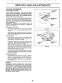
TO REMOVE
WHEEL
(See Fig. 39)
Make sure transaxle is in neutral
Loosen two Iocknuts on tie rod.
FOR
REPAIRS
Block up axle securely.
Remove axle cover, retaining ring and washers to allow
wheel removal (rear wheel contains a square key - Do
not lose).
Repair tire and reassemble,
On rear wheels only: align grooves in rear wheel hub
and axle Insert squarekey.
Replace washers and snap retaining ring securely in
axle groove.
Replace axle cover.
LOOK GATE
WASHERS
RETAINING
FIG. 37
Turn center rod until gearshift lever fails into neutral
lock gate on fender console
AXLE
COVER
Q
_"_
SQUARE
KEY
(REAR WHEELS
ONLY)
FIG. 39
TO REPLACE
FUSE
(See
Fig. 40)
Replace with 30 amp automotive-type plug-in fuse.
fuse holder is located behind the dash.
TRANSAXLE
FIG. 38
Tighten !ocknuts securely.
FUSE
TO ADJUST
STEERING
WHEEL
ALIGNMENT
If steering wheel crossbars are not horizontal (left to right)
when wheels are positioned
straight forward, remove
steering wheel andreassemble
per instructions in the
Assembly section of this manual.
FIG. 40
23
The
SERVICE AND ADJUSTMENTS
TO START ENGINE WITH A WEAK
(See Figs. 41 and 42)
BATTERY
TO REPLACE
HEADLIGHT
BULB
Raise hood.
Pull bulb holder out of the hole in the backside of the
grill.
CAUTION: Lead-acid batteries generate !
explosive gases. Keep sparks, flame and i
smoking materials away from batteries.
Always wear eye protection when around !
batteries,
Replace bulb in holder and push bulb holder securely
back into the hole in the backside of the grill
Close hood.
t
If your battery is too weak to start the engine, it should be
recharged.
If "jumper cables" are used for emergency
starting, follow this procedure:
IMPORTANT:
YOUR UNIT tS EQUIPPED WITH A 12
VOLT NEGATIVE GROUNDED SYSTEM. THE OTHER
VEHICLE MUST ALSO BE A 12 VOLT NEGATIVE
GROUNDED SYSTEM, DO NOT USE YOUR TRACTOR
BATTERY TO START OTHER VEHICLES.
INTERLOCKS
AND
RELAYS
Loose or damaged wiring may cause your tractor to run
poorly, stop running, or prevent it from starting.
Check wiring. See electrical wiring diagram in Repair
Parts section of this manual.
TO REMOVE HOOD AND GRILL ASSEMBLY
(See Figs. 43 and 44)
Lifthoo& Disconnect headlight wiring connection.
Unscrew one screw at rear of each side panel
"POSITIVE"
(+)
"NEGATIVE"
(-)
FIG. 41
TO ATTACH JUMPER CABLES Connect each end of the RED cable to the POSITIVE
(+) terminal of each battery, taking care not to short
against chassis,
Connect one end of the BLACK cable to the NEGATIVE (-) terminal of fully charged battery.
Connect the other end of the BLACK cable to good
CHASSIS GROUND, away frorrr fuel tankand battery.
FIG. 43
Pivot hood and side panel forward and lift off tractor.
To replace, reverse above procedure.
WIRE
CONNECTION
LH, PANEL
BOLT
FIG. 44
FIG. 42
TO REMOVE CABLES, REVERSE ORDERBLACK cable first from chassis and fully charged
battery.
RED cable last from both batteries,
24
SERVnCE AND ADJUSTMENTS
ENGINE
TO ADJUST
TO ADJUST
(See Fig, 45)
THROTTLE
CONTROL
CABLE
(See Fig.
46)
With engine not running, move choke control (located
on dash panel) to full'CHOKE"
position.
With engine not running, move throttle control lever to
"FAST" position.
Remove air cleaner cover, filter and spitback plate to
expose carburetor choke (See "AIR FILTER" in customer responsibilities section).
Check that speed control lever is against stop screw. If
it is not, loosen clamp screw and pull throttle cable until
lever is against screw, Tighten clamp screw securely.
Choke should be closed. If it is not, loosen casing
clamp screw and move choke until choke is completely
closed, Tighten casing clamp screw securely.
Reassemble air cleaner.
CLAMP
O,RCL
\
CONTROL
The choke contro) has been preset at the factory and
ad ustmentshould not benecessary. Checkadjustmentas
described below before loosen ng cab e, f ad ustment s
necessary, proceed as follows:
The throttle control has been preset at the factory and
ad ustment should not be necessary. Check adjustment as
descr bed be ow before oosen ng cab e. f adjustment s
necessary, proceed as follows:
ouZ
CHOKE
/
i
_WIVEL
CHOKE
CONTROL
SCREW
FIG. 45
FIG, 46
25
SERVICE AN
TO ADJUST
ADJUSTMENTS
CARBURETOR
(See Figs. 47 and 48)
IDLE SPEED
The carburetor has been present at the factory and adiustment should not be necessary, However, minor adjustment may be required to compensate for differences in fuel,
temperature, altitude or load, If the carburetor does not
need adjustment, proceed as follows:
In general, turning the mixture screw in (clockwise) decr eases the supply of fuel to the engine giving a leaner fuel/
air mixture, Turning the mixture screw out (counterclockwise) increases the supply of fuel to the engine giving a
richer fuel/air mixture,
IMPORTANT: DAMAGE TO THE NEEDLES AND THE
SEATS IN CARBURETOR MAY RESULT IF SCREW IS
TURNED IN TOO TIGHT,
PRELIMINARY
IDLE MIXTURE
SCREW
THRO_'LE
LEVER
SETTING -
Be sure you have a clean air filter, and the throttle
control cable and choke are adjusted properly (see
above).
FIGo47
With engine off turn idle mixture screw in (clockwise)
closing it finger tight and then turn out (counterclockwise) 1-1/4 to 1-1/2 turns.
IDLE SPEED
FINAL SETTING Start engine and allow to warm for five minutes. Make
final adjustments with engine running and shift/motion
control lever in "NEUTRAL" position.
SCREW_I
With throttle control lever in "SLOW" position, hold
throttle lever against idle speed screw and adjust idle
speed screw to obtain 1200 to 1400 RPM.
While still holding throttle lever against idle speed
screw, turn idle mixture screw in (clockwise) until
engine begins to die and then turn out (counterclockwise) until engine runs rough. Turn screw to a point
midway between those two positions.
FIG. 48
Continue to hold throttle lever against idle speed screw
and adjust idle speed screw to obtain 900 to 1200 RPM.
Release throttle lever_
ACCELERATION
_IDLE
THROTTLE
LEVER
TEST-
Move throttle control lever from "SLOW" to "FAST"
position. If engine hesitates or dies, turn idle mixture
screw out (counterclockwise) 1/8 turn. Repeat test
and continue to adjust, if necessary, until engine accelerates smoothly.
High speed stop is factory adjusted. Do not adjustodamage
may result.
IMPORTANT:
NEVER TAMPER WITH THE ENGINE
GOVERNOR, WHICH IS FACTORY SET FOR PROPER
ENGINE SPEED OVERSPEEDING THE ENGINEABOVE
THE FACTORY
HIGH SPEED SETTING
CAN BE
DANGEROUS. IFYOU THINKTHE ENGINE-GOVERNED
HIGH SPEED NEEDS ADJUSTING, CONTACT YOUR
NEAREST SEARS SERVICE CENTER, WHICH HAS
PROPER EQUIPMENTAND EXPERIENCETO MAKEANY
NECESSARY ADJUSTMENTS.
26
MIXTURE
SCREW
-i
STORAGE
ENGINE
Immediately prepare your unit for storage at the end of the
season or if the unit will not be used for 30 days or more.
FUEL SYSTEM
IMPORTANT:
IT IS IMPORTANT TO PREVENT GUM
DEPOSITS FROM FORMING IN ESSENTIAL FUEL
SYSTEM PARTS SUCH AS CARBURETOR, FUEL FILTER,
FUEL HOSE, OR TANK DURING STORAGE. ALSO,
EXPERIENCE INDICATES THAT ALCOHOL BLENDED
FUELS (CALLED GASOHOL OR USING ETHANOL OR
METHANOL) CAN ATTRACT MOISTURE WHICH LEADS
TO SEPARATION AND FORMATION OFACIDS DURING
STORAGE ACIDIC GAS CAN DAMAGE THE FUEL
SYSTEM OF AN ENGINE WHILE IN STORAGE,
CAUTION: Never store the tractor with
gasoline in the tank inside a building
where fumes may reach an open flame
or spark.
Allow the engine to ¢ool
before storing In any enclosure.
TRACTOR
Drain the fuel tank.
Remove mower from unit for winter storage. When mower
is to be stored for a period of time, clean it thoroughly,
remove all dirt, grease, leaves, etc. Give blades and
underside of housing a good coat of grease er rust preventative. Store in a clean, dry area,
Start the engine and let it run until the fuel lines and
carburetor are empty.
Never use engine or carburetor cleaner products tn the
fuel tank or permanent damage may occur.
Use fresh fuel next season,
Clean entire tractor (See "CLEAN ING" in the Customer
Responsibilities section of this manual).
NOTE; Fuel stabilizer is an acceptable alternative in
minimizing the formation of fuel gum deposits during storage. Add stabilizer to gasoline in fuel tank or storage
container, Run engine at least 10 minutes after adding
stabilizer to allow the stabilizer to reach the carburetor. Do
not drain the gas tank and carburetor if using fuel stabilizer.
Inspect and replace belts, if necessary (See belt replacement instructions in the Service and Adjustments
section of this manual)
Lubricate as shown in the Customer Responsibilities
section of this manual
Be sure that all nuts, bolts and screws are securely
fastened Insaect moving parts for damage, breakage
anu wear _epiace _[necessaiy
ENGINE
OIL
Drain oil (with engine warm) and replace with clean engine
oil, (See "ENGINE" in the Customer Responsibilities section of this manual),
Touch up all rusted or chipped paint surfaces; sand
lightly before painting
CYLINDERS
BATTERY
Fully charge the battery for storage
Remove spark plug(s),
After a period of time in storage, battery may require
recharging
Pour one ounce of oil through spark plug hole(s) into
cylinder(s).
To help prevent corrosion and power leakage during
long periods of storage, battery cables should be
disconnected and battery cleaned thoroughly (See
"TO CLEAN BATTERY AND TERMINALS" in the
Customer Responsibilities section of this manual)
Turn ignition key to "START" position for a few seconds
to distribute oil.
Replace with new spark plug(s).
OTHER
After cleaning, leave cables disconnected and place
cables where they cannot come in contact with battery
terminals
Do not store gasoline from one season to another,
Replace your gasoline can if your can starts to rust,
Rust and/or dirt in your gasoline will cause problems.
Be sure battery drain tube is securely attached to drain
in battery tray.
If possible, store your unit indoors and cover it to give
protection from dust and dirt
Cover your unit with a suitable protective cover that
does net retain moisture, Do nat use plastic. Plastic
cannot breathe which allows condensation to form and
will cause your unit to rust.
IMPORTANT: NEVER COVER TRACTOR WHILE ENGINE
AND EXHAUST AREAS ARE STILL WARM,
27
TROUBLESHOOTING
PROBLEM
wgt not start
POINTS
CAUSE
1
Out of fuel
2
3
4.
5,
6
7,
Engine not "CHOKED"
Engine flooded.
Badspark plug
Dkty air filtel.
Dirty fuel filter
Water in fuel
CORRECTION
1.
Fill fuel tank,
properly
2,
3
4.
5
6.
7
8
9,
t 0
Loose or d,"maged wiring
Carburetor out of adjustment
Engine valves out of adjustment
8
9
f0
See "TO START ENGINE" In Operation section
Walt several minutes before attempting to start
Replace spark plug,
Cleanheplace air filter
Replace fuel filter
Drain fuel tank and carburetor, refill tank with fresh
gasoline and replace fuel filter.
Check allwlring.
Contact Sears Service Center/DepartmenL
Contact Sears Service Cantel/Departmant
Hard to start
1
2.
3
4
5,
6
7,
8
Dttty air filter,
Bad spark plug
Weak or dead battery,
Dirty fuel filter,
Stale or dirty fue!
Loose or damaged wiring
Carburetor out of adjustment
Englnevalves outof adjustment
1, Clean/replace ak filter
2, Replace spark plug.
3, Recharge or replace battery.
4, Replacefuelfilter
5 Drainfuel tank and refill with freshgasoline,
6 Check allwlrlng,
7. Contact Sears Service Canter/Department
8 Contact Sears ServlceCenter/DepartrnenL
Engine will not tern over'
1
2
3
4
Clutch/btake pedal not depressed
Attachment clutch is engaged
Weak or dead battery,
Blown fuse
5
6.
7
8,
9
Corroded battery terminals
Loose or damagedwldng
Faulty Ignition switch
Faulty solenoid or starter
Faulty operator presence swttch(es),
1
2,
3
4.
5,
6
7.
8
9
Depress clutch/brakepedal.
Disengage attachment clutch
Rechargeor replace battery,
Replace fuse,
Clean battery telmlnals
Check all wiring
Check/replace Ignition switch.
Check/replace solenoid orstarter,
Contact Sears Service Center/Department.
Engine clicks but will not
start
1
2,
3.
4
Weak or dead battery,
Corroded battery terminals
Loose or damaged wiring
Faulty solenoid or starter
1
2,
3
4.
Rechargeor replace battery.
Clean battery terminals
Check allwldng
Check/replace solanald or starter,
Lose of power
1
2
3
4
5
6
7
8
9
Cuttingtoo much grass/too fast
Throttle in"CHOKE"position.
Build-up of grass, leaves and trash under mower,
Dirty air filter,
Low oil level/dirty oil
Faulty spark plug
Dirty fuel filter
Stale or dirty fuel,
Water in fuel
1,
2
3.
4,
5
6
7
8.
9.
t0
Spark plug wire loose,
11. Dirty engineair screen/fins.
12 Dirty/clogged muffler
13 Looseor damagedwlrlng
14, Carburetor out of adjustmanL
15. Enginevalves out of adjustment,
i,
Set In"Higher Cut" position/reduce speed.
Adjust throttlecontrol,
Clean underalde of mower housing.
Clean/replace air filter
Check oil level/change oil,
Clean and regap or change spark plug
Replace fuel filter,
Drain fuel tank and refill with fresh gasoline,
Drain fuel tank and carburetor, refill tankwith flesh
gasoline and replace fuel filter.
10, Connect and tighten spark plug wire,
11 Clean engine air ecrean/flns.
12 Clean/replace muffler.
13 Check all wiring.
14. Contact Sears Service Center/Department
15. Contact Sears Service CenteriDepartmant
n
Excessive vibration
1, Worn, bent or looseblade.
2. Bent blade mandrel
3 Loose/damaged part(s)
t.
2
3
28
Replace blade. Tighten blade bolt,
Replace blade mandrel.
T[ghtenloose part(s). Replace damaged parts
TROU
LESHOOTING POINTS
PROBLEM
CAUSE
CORRECTION
Engine continues to run
when operatorteaves seat
with a_achment clutch
engaged
1,
Faulty operator-safety presence control system
1
Check wiring, switches and connections. If not
corrected, contact Sears Service Center/Department
Poorcut-uneven
1.
2.
3
4.
Worn, bent or loose blade.
Mower deck not level.
Buildup of grass, leaves, and trash under mower.
Bent blade mandrel.
1.
2,
3,
4,
Replace blade. Tighten blade bolt
Level mower deckClean underside of mower housing.
Replace blade mandrel,
Mower biades wtll not
rotate
1 Obstruction in clutch mechanism.
2_ Mower drive belt out of adjustmenL
3, Worn/damaged mower drive belt.
4. Frozenid]er pulley
5 Frozen blade mandrel
1,
2
3
4.
5
Remove obstruction,
Adjust mower drive belt
Replace mower drive belt
ReplaceidIer pulley
Replace blade mandrel,
Poor grass discharge
1. Engine speed too slow,
2 Travel speedtoo fast
3. Wet grass.
4 Mower deck not level
5 Low/uneven tire air pressure,
6 Worn, bent or !oose blade.
7 Buildup of grass, leaves and trash under mower,
8, Mower drive belt worn or out of adjustment
9 Blades improperly installed.
10, Improperblades used.
1.
2
3.
4
5
6.
7.
8.
9_
10.
Place throttle control in "FAST" position.
Shift to slower spee&
Allow grass to dry before mowing,
Level mower deck
Checktires for proper air pressure.
Replace/sharpen blade. Tighten blade bolt.
Clean underside of mower housing.
Replace/adjust mower drive belt.
Reinstal! blades sharp edge down
Replace with blades listed in this manua!
Headlight(s) not working
(if so equipped)
1.
2,
3,
4
5,
Switch is "OFF"
Bulb(s) burned out.
Faulty light switch
Loose or damaged wiring
B!own fuse
1, Turn switch "ON"
2- Replace bulb(s),
3 Check!replace light switch
4 Checkwlrlng and connections
5, Replace fuse
Battery win not charge
1,
2.
3.
4
Bad battery cell(s).
Poor cable connections
Faulty regulator (if so equipped),
Faulty alternator
1
2.
3
4
Replace battery
Check/clean all connections.
Replace regulator,
Replace alternator.
Engine "backfires"
when turning engine
"OFF"
1
Engine throttle control not set at "SLOW"
position for 30 seconds before stopping engine
1.
Move throttle control to "SLOW" position and allow
to id!e for 30 seconds before stopping engine.
29
®
OWNER'S
MANUAL
18.0 HP TWBN CYLINDE
44"
OWER
6 SPEE
GARDEN TRACTOR
Each tractor has its own model number.
number
MODEL NO,
917.255942
Each engine has its own model
The Model Number for your tractor will be found on the model plate
located under the seat.
The model number' for' your engine will be found on the blower housing
All parts listed herein may be ordered from any Sears, Roebuck and Co.
Sewice Center and most Retail Stores,
WHEN ORDERING REPAIR PARTS, ALWAYS
ING INFORMATION:
• PRODUCT-
HOW TO ORDER
REPAIR PARTS
GIVE THE FOLLOW-
GARDEN TRACTOR
• MODEL NUMBER - 917.255942
• ENGINE MODEL NUMBER - 0422707, TYPE NUMBER 1254-01
• PART NUMBER
• PART DESCRIPTION
Your Sears merchandise has added value when you consider Sears has
service units nationwide staffed with Sears trained technicians._ professional technicians specifically trained to insure that we meet our pledge
to you, we service what we sell.
Sears, Roebuck and Co., Hoffrnan Estates, IL 60179 U.S.A.
138185
9.11 92
%
PRINTED IN U,S.A.