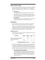
1
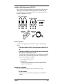
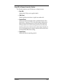
SPREAD-SPECTRUM
RADIO MODEM
INSTALLATION KIT
F O R Y DI R A D I O S ,
OMNI- DIRECTIONAL AND
DIRECTIONAL (YAGI) ANTENNAS
I NTRODUCTION
The Spread-Spectrum Radio Modem Installation Kit contains the materials necessary to connect a WeatherLink® data logger to a YDI model 910-DAVIS radio
modem. You will need to obtain the radio modem (RM) directly from YDI. See
the accompanying sheet for YDI product and contact information.
Three versions of the installation kit are available. One includes an omni-directional antenna (#7623-003) and mounting hardware, one a directional (Yagi)
antenna (#7623-008) and mounting hardware, and one includes the mounting
hardware, with no antenna (it is intended for use with the 12dB Yagi antenna
from YDI). Installation instructions for all three kits are contained in this manual. You will need one installation kit for each node in your communications
net. Two are required for a point-to-point link.
C OMPONENTS
All versions of the installation kit contain the following components. Please
make sure you have all components before continuing.
Jumper
AOM Wires (Yellow, Green, & White)
Power Cable
Power Adapter
Mounting Plate
Battery Wire
Terminal
Block
Modular Cable,
4' (1.2 m)
Velcro Strap
Tab Adapter
#6 x 3/8" Sheet Metal Screws
#4 x 3/8" Sheet Metal Screw
#6 x 3/4" Wood Screws
Phone Modem
Adapter (L1)
WeatherLink
PC Radio DB-25
Adapter (L2)
Modem Configuration
Disc
Product # 7632-003, 7632-008 & 7632-912
Installation Kit & 3dB Omni-Directional (Whip) Antenna (#7632-003)
The following components are contained in the Installation Kit & 3dB OmniDirectional (Whip) Antenna package.
Antenna, 896-940 MHz
3dB Omni-Directional
Mounting Hardware
Ground Plane &
Antenna Cable
Installation Kit & 8.5dB Directional (Yagi) Antenna (#7632-008)
The following components are contained in the Installation Kit & 8.5dB Directional (Yagi) Antenna package.
2-3/8" U-Bolts & Hardware
1-1/4" U-Bolts & Hardware
1/4" x 1-1/2" Lag Screws
Washers
Antenna, 896-940 MHz
8.5 dB Yagi, with cable
Antenna Mast
Brackets
2-1/8" U-Bolts & Hardware
Mast-Mounting
Blocks
Page 2
Spread-Spectrum Radio Modem Installation Kit
Installation Kit Without Antenna (#7632-912)
This kit provides all necessary hardware to mount and use a third-party Yagi
antenna, such as the 12dB Directional (Yagi) Antenna (available from YDI:
model 918-10), which allows a greater transmission distance than the Davissupplied 8.5dB antenna (#7632-008).
2-3/8" U-Bolts & Hardware
1-1/4" U-Bolts & Hardware
1/4" x 1-1/2" Lag Screws
Antenna Mast
Brackets
Antenna Cable,
N-to-BNC
Power Components
You will need to supply power to the RM site, using one of the following
options.
✦ If AC power is available at the RM site, use the power adapter supplied with this
kit.
✦ If AC power is not available or if you want to use solar power, use the Solar Power
Kit (#7708) and 6.5-Amp-Hour Battery (#7711).
If solar power is used, it will be necessary to switch the power to the RM
so that it is on for only limited periods in order to conserve the power
drawn. Two alternatives are available:
✦ Alarm Output Module (#7736)
✦ Timer (#7682)
The Timer is recommended unless the Alarm Output Module is
required for other purposes.
WeatherLink Components
You will need the following item from your WeatherLink package:
✦ PC COM Port Adapter
On older versions of the WeatherLink, this adapter was labelled AT
Adapter.
Components
Page 3
Optional Components
The following optional components may be necessary for your installation.
✦ Antenna Mast-Mount Kit (#7995)
The hardware provided with the omni-directional antenna enables you
to mount the antenna on the Sensor Mounting Arm. If you want to
mount it on a pole, post, or wall or raise it above the Sensor Mounting
Arm, use the Antenna Mast-Mount Kit.
Note: The antenna should be located as high as possible and away from buildings and other
obstructions, if possible. It is necessary that the path between the field and base station
antennas be completely unobstructed (line-of-sight). Even trees and other vegetation
can reduce the signal intensity.
✦ Short-Range Modem Pair (#7875)
The need for a line-of-sight transmission path may dictate that the base
station antenna be located more than 40' (12 m) from the computer to
which it is connected. The RM should be located near the antenna (a
longer co-axial antenna cable could be used, but this will reduce signal
strength), so it is necessary (in this case) to use the Short-Range Modem
Pair for communication between the RM and the computer.
✦ Radio Surge Protector for Spread-Spectrum and UHF Radio Modems (#7683)
If the RM is located in an area where lightning strikes are a possibility
you should use the Radio Surge Protector to provide surge protection
between the antenna and the RM.
Note: We recommend the use of the Radio Surge Protector in ALL installations.
✦ Repeater
If line-of-sight is not readily available or range is exceeded it may be necessary to install a repeater RM site between the field and base station.
Contact YDI directly for assistance in designing, obtaining, and configuring such a link. The WeatherLink software does not support the use of
repeaters and the supplied configuration program cannot configure
them.
✦ Terminal Box (#7774)
If you need to extend the length of the antenna cable and the connection
is not weather-proof, you may house the connection inside Davis’s Terminal Box.
Page 4
Spread-Spectrum Radio Modem Installation Kit
T OOLS
AND
M ATERIALS R EQUIRED
In addition to the components listed above, you may need some of the following tools and materials. Please be sure you have everything you need before
beginning the installation.
✦ 3/4" Galvanized Pipe or Antenna Mast, maximum outside diameter of 1-1/4"
(32 mm)
This pipe/mast is required to mount the directional (Yagi) antenna and
may be used in conjunction with the Antenna Mast-Mount Kit to mount
the omni-directional antenna above the Sensor Mounting Arm.
✦ Phillips Screw Driver
✦ Slotted Screw Driver
✦ Electric Drill with 7/32" (5.5 mm) 3/16" (4.8 mm) drill bit
✦ Adjustable Wrench or Socket Set
Tools and Materials Required
Page 5
T YPICAL I NSTALLATIONS
The illustrations below show typical installations. A checklist of installation
steps for each installation is provided.
AC-Powered Field Station
The illustration below shows an AC-powered field station and radio modem (RM).
Console
1-1/4"
PHONE MODEM
Adapter (L1)
+12 V
Radio
Modem
WeatherLink®
PHONE MODEM
Adapter
Sensor
Interface
Module
L1
Part
7870
Mounting Plate
Radio Surge Protector (optional)
To Antenna
Protector Ground
Power
Adapter
You must complete the following steps for this installation.
1. Configure RM (see “Configuring The Radio Modem” on page 11).
2. Test RM (see “Testing the Radio” on page 14).
3. Install antenna (see “Installing Omni-Directional Antenna” on page 16 or “Installing
Directional Antenna” on page 17).
4. Install Radio Surge Protector (optional).
Consult the manual supplied with the Radio Surge Protector for instructions.
5. Install RM (see “Installing Radio Modem” on page 20).
6. Check wiring.
Before you apply power to the system, review your wiring to make sure all
connections are correct.
7. Connect power to system.
Make sure the antenna is connected to the RM before connecting power; damage
may occur if you operate without an antenna. Plug the power adapter into a
power outlet and its cable into the RM’s power jack. Make sure the Power
indicator light on the RM is on.
Page 6
Spread-Spectrum Radio Modem Installation Kit
AC-Powered Base Station
The illustration below shows an AC-powered base station and radio modem
(RM).
Multi-Purpose Shelter
Radio
Modem
Short-Range
Modem
and Adapter
(optional)
Mounting
Plate
PC RADIO
DB-25
Adapter (L2)
Part
7943
WeatherLink®
PC RADIO
DB-25 Adapter
Radio Surge
Protector (optional)
L2
Power
Adapter
To Antenna
To Base Computer (PC)
+12 V
You must complete the following steps for this installation.
1. Configure RM (see “Configuring The Radio Modem” on page 11).
2. Test RM (see “Testing the Radio” on page 14).
3. Install antenna (see “Installing Omni-Directional Antenna” on page 16 or “Installing
Directional Antenna” on page 17).
4. Install Radio Surge Protector (optional).
Consult the manual supplied with the Radio Surge Protector for installation
instructions.
5. Install Short-Range Modem Pair (optional).
Consult the manual supplied with the Short-Range Modem Pair for instructions. Consult the illustration above for positioning. Skip this step if the base
station is located within 40’ (12 m) of the computer.
6. Install RM (see “Installing Radio Modem” on page 20).
7. Check wiring.
Before you apply power to the system, review your wiring to make sure all
connections are correct.
8. Connect power to system.
Make sure the antenna is connected to the RM before connecting power; damage
may occur if you operate without an antenna. Plug the power adapter into a
power outlet and its cable into the RM’s power jack. Make sure the Power
indicator light on the RM is on.
Typical Installations
Page 7
Solar-Powered Using Timer
The illustration below shows a solar-powered field station and radio modem
(RM) using a Timer for power conservation.
Regulator
Battery
Console
1-1/4"
PHONE MODEM
Adapter (L1)
Power
Cable
Radio
Modem
WeatherLink®
PHONE MODEM
Adapter
Sensor
Interface
Module
Terminal
Block
L1
Part
7870
Timer
Mounting Plate
Radio Protector (optional)
To Antenna
Protector Ground
You must complete the following steps for this installation.
1. Configure RM (see “Configuring The Radio Modem” on page 11).
2. Test RM (see “Testing the Radio” on page 14).
3. Install antenna (see “Installing Omni-Directional Antenna” on page 16 or “Installing
Directional Antenna” on page 17).
4. Install Solar Power Kit and 6.5-Amp-Hour Battery (see “Installing Solar Power Kit &
Battery” on page 20).
5. Install Radio Surge Protector (optional).
Consult the manual supplied with the Radio Surge Protector for installation
instructions.
6. Install RM (see “Installing Radio Modem” on page 20).
7. Install Timer (see “Installing Timer” on page 24).
8. Install terminal block (see “Installing Terminal Block” on page 24).
9. Connect Timer wires (see “Connecting Timer Wires” on page 25).
Page 8
Spread-Spectrum Radio Modem Installation Kit
10. Check wiring.
Before you apply power to the system, review your wiring to make sure all
connections are correct and all wires firmly secured in the proper terminal.
11. Connect power to system.
Make sure the rest of your installation is complete before connecting power. In particular, make sure the antenna is connected to the RM before connecting power;
damage may occur if you operate without an antenna. Connect the battery cable
to B2 on the regulator circuit. Connect the solar panel cable to B1 on the regulator circuit.
12. Finalize the installation by programming and testing the Timer (see “Finalizing the
Installation” on page 28).
Solar-Powered Using Alarm Output Module
The illustration below shows a solar-powered field station and radio modem
(RM) using an Alarm Output Module (AOM) for power conservation.
Regulator
Battery
Alarm Output
Module
Console
1-1/4"
PHONE MODEM
Adapter (L1)
Radio
Modem
WeatherLink®
PHONE MODEM
Adapter
L1
Part
7870
Power
Cable
Terminal
Block
Sensor
Interface
Module
Mounting Plate
Radio Protector (optional)
To Antenna
Protector Ground
You must complete the following steps for this installation.
1. Configure RM (see “Configuring The Radio Modem” on page 11).
2. Test RM (see “Testing the Radio” on page 14).
3. Install antenna (see “Installing Omni-Directional Antenna” on page 16 or “Installing
Directional Antenna” on page 17).
Typical Installations
Page 9
4. Install Solar Power Kit and 6.5-Amp-Hour Battery (see “Installing Solar Power Kit &
Battery” on page 20).
5. Install Alarm Output Module
Consult the manual supplied with the Alarm Output Module for instructions. Consult the illustration above for positioning.
6. Install Radio Surge Protector (optional).
Consult the manual supplied with the Radio Surge Protector for installation
instructions.
7. Install RM (see “Installing Radio Modem” on page 20).
8. Install terminal block (see “Installing Terminal Block” on page 24).
9. Connect Alarm Output Module wires (see “Connecting Alarm Output Module Wires”
on page 27).
10. Check wiring.
Before you apply power to the system, review your wiring to make sure all
connections are correct and all wires firmly secured in the proper terminal.
11. Connect power to system.
Make sure the rest of your installation is complete before connecting power. In particular, make sure the antenna is connected to the RM before connecting power;
damage may occur if you operate without an antenna. Connect the battery cable
to B2 on the regulator circuit. Connect the solar panel cable to B1 on the regulator circuit.
12. Finalize the installation by programming and testing the AOM (see “Finalizing the
Installation” on page 28).
Page 10
Spread-Spectrum Radio Modem Installation Kit
C ONFIGURING T HE R ADIO M ODEM
As shipped from the factory, the radio modem (RM) may not be compatible
with your WeatherLink. Follow the instructions below to configure the RM.
Connect the RM to your Computer
The first part of the procedure requires you to connect the RM to your computer.
1. Connect the PC COM Port Adapter to a serial port on your PC.
2. Connect one end of the modular cable to the PC COM Port Adapter.
3. Connect the PC RADIO DB-25 Adapter to the DB25 connector on the RM.
4. Connect the other end of the modular cable to the PC RADIO DB-25 Adapter.
Modem
(RM)
PC Com
Port
PC
PC COM Port
Adapter
PC RADIO
DB-25 Adapter (L2)
Modular
Cable
Power the RM
Provide power to the RM by plugging the power adapter into the power jack
on the RM and then into a power outlet.
MODEM
(RM)
Power
Adapter
(PC RADIO DB-25
Adapter not shown)
Configuring The Radio Modem
Page 11
Run The Modem Configuration Program
Use the supplied modem configuration program to configure the RM.
1. Place the Modem Configuration Disk in your disk drive.
2. Choose Run from the File Menu (Windows 3.1) or the Start Menu (Windows 95).
3. Type A:\CONFIG and press Enter (or choose Ok).
The Wireless Modem Configuration Program dialog box appears.
4. Select YDI Model 910 Radio from the Model Type drop-down list.
5. Select the COM port to which the RM is connected from the COM Port drop-down list.
If you don‘t know the serial port number, start by choosing COM 1. If you
get a program error when you attempt to configure the RM, try with COM 2,
and so on until you find the correct serial port setting.
6. Select a “name” for this RM from the Radio Name drop-down list.
You may choose between “Base” and a series of numbered “Remote” stations.
7. Select the channel on which you want the RM communicating from the Channel dropdown list (all radios in the network must use the same channel).
Consult the manual supplied by the radio modem manufacturer for information on choosing a channel.
Page 12
Spread-Spectrum Radio Modem Installation Kit
8. Choose between Point-to-Point and Multi-Point operation.
The Point-to-Point option configures the "Base" radio and the "Remote 1" to
act as a transparent connection. Thus it will work with all existing Davis
Instruments software. You must configure both the "Base" radio and the
"Remote 1" radio with the Point-to-Point option selected. The Remote radio
must be named "Remote 1"; the program will give you an error message if
you try to use another name. If you switch from a Point-to-Point configuration to a Multi-Point configuration, both the base and field station will need
to be reconfigured using the Multi-Point option.
The Multi-Point configuration supports multiple remote weather stations
from a single base radio, but you can only use it if your software supports
Multi-Point networking. At the present time, only the GroWeatherLink software supports Multi-Point configurations. If you have only one field station,
you may still want to use the Multi-Point configuration. It will take slightly
more time to establish a connection, however, if you add a field station later,
you will not have to bring the existing stations in to reconfigure them for
Multi-Point operation.
9. Select the WeatherLink baud rate (typically 2400) from the WeatherLink Baud Rate
drop-down list.
10. Select the current baud rate of the RM from the Radio’s Current Baud Rate drop-down list.
The RM comes from the factory with the baud rate set to 2400.
11. When finished, choose Configure.
The program will attempt to locate and configure your RM. If you encounter
an error, make sure you have selected YDI Model 910 Radio and then try different serial ports and radio baud rates until the configuration is successful.
12. Once configuration is complete, remove power from the RM and disconnect the RM
from your computer.
Configuring The Radio Modem
Page 13
T ESTING
THE
R ADIO
Before proceeding with the installation, test the radio modem (RM) by assembling the field station(s) and base station in the same room. Make sure to test
each field station RM before installing.
Follow the procedure below to test the station.
1. If necessary, connect the weather station to the WeatherLink and install the software
as explained in the WeatherLink manual.
2. Position the antennas for the field and base stations at least 8’ (3 m) apart and orient
them as described below, depending on the type of antennas you are using.
✦ Omni-Directional
If using omni-directional antennas, orient the antennas at right
angles to each other.
✦ Directional (Yagi)
If using directional antennas, place the antennas horizontal, at the
same level, with the booms parallel.
✦ Omni-Directional and Directional
If using omni-directional and directional antennas together, place
the omni-directional antenna in a vertical position and the directional antenna horizontal, pointing 90˚ away from the omni-directional antenna.
Separate antennas by 8' (2.5m) minimum.
8'
8'
8'
3. Connect the field station radio modem as shown below. Plug the power adapter into a
wall outlet and make sure the radio modem’s Power light comes on.
FIELD STATION:
To Power Adapter
Radio Modem
WeatherLink®
PHONE MODEM
Adapter
L1
To WeatherLink
L1
Part
7870
To Antenna
Page 14
Spread-Spectrum Radio Modem Installation Kit
4. Connect the base station radio modem as shown below. Plug the power adapter into a
wall outlet and make sure the radio modem’s Power light comes on.
BASE STATION:
To Power Adapter
Radio Modem
WeatherLink®
PC RADIO
DB-25 Adapter
To PC
L2
Part
7943
To Antenna
5. Supply power to the weather station using the 200mA power adapter supplied with
the station.
6. Use the Test (or Connection Test) button in the WeatherLink software’s serial port
dialog box to make sure you can successfully connect to the field radio modem/
weather station.
Consult the software manual for instructions on selecting the correct serial
port settings and testing the connection.
7. If successful, continue with the installation.
If you receive an error message, try testing the connection again. If you are
still not able to successfully connect, consult “Troubleshooting” on page 32.
Note: If there is a problem with interference from another radio source, try changing channels. Reconfigure all of the radio modems (see “Configuring The Radio Modem” on page 11). You
may choose between three channels; make sure all radio modems are set to the same channel.
Testing the Radio
Page 15
I NSTALLATION
Follow the instructions below to install the components of your RM system. In
many cases, you will have to consult the instruction manual supplied with
another component for specific instructions. Installation diagrams are supplied
as a guide.
Installing Omni-Directional Antenna
You may mount the omni-directional antenna on the Sensor Mounting Arm. To
mount on a pipe, post, wall, or to raise it above the Sensor Mounting Arm, use
the Antenna Mast-Mount Kit.
✦ Installing on Sensor Mounting Arm (SMA)
Attach the antenna to the ground plane as shown below, screw on until
snug. Attach the ground plane to the SMA using the #8-32 x 3/4" screws,
flat washers, split lock washers, and hex nuts as shown below.
Note: It may be necessary to drill one or two holes in the SMA to accommodate the ground
plane. If so, use the holes in the ground plane as a guide and drill holes in the SMA using
a 7/32" (5.5mm) drill bit.
8-32 × 3/4" Screw
Flat Washer
Onmi
Antenna
Ground Plane
Sensor Mounting Arm
1"
Ground
Plane
If necessary, drill holes using
7/32" (5.5mm) drill bit.
Flat Washer
Split Lock Washer
#8 Hex Nut
Antenna Cable
Page 16
Spread-Spectrum Radio Modem Installation Kit
Installing Directional Antenna
The directional antenna may be mounted in either the vertical or horizontal
plane. If it is communicating with an omni-directional antenna it must be
mounted in the vertical plane. If communicating with another directional
antenna, the two may be either vertical or horizontal; both must be in the same
plane, however.
Note: If an interfering radio source is nearby it will be helpful to orient the antennas opposite (orthogonal) to the plane of the interference. AM radio transmissions are typically vertically polarized,
so horizontal antennas will better reject AM radio interference. Television and FM radio transmissions are usually horizontally polarized, so vertical antennas will better reject TV and FM
radio interference.
Installation
Page 17
✦ Mounting Antenna Mast on Sensor Mounting Arm Support Pipe
Attach the antenna to the antenna mast as shown below. If the outside
diameter of the antenna mast is less than 1.16" (30 mm), omit the mastmounting blocks. If installing the 12dB Yagi from YDI, connect the antenna
cable (N-to-BNC) to the short antenna cable attached to the Yagi. Attach
the antenna mast brackets to the bottom of the antenna mast using the
1-1/4" U-bolts, washers, lock washers, and hex nuts as shown below.
Attach the antenna mast to the support pipe using the 2-1/4" U-bolts,
washers, lock washers, and hex nuts as shown below.
1-1/4" U-Bolts
Antenna Mast
up to 1-1/4" (32 mm)
Outside Diameter
(user-supplied)
Yagi Antenna,
(8.5db Yagi with
vertical polarization shown)
Mast-Mounting
Blocks
Do not use if
mast diameter is
less than 1.16"
(30 mm).
Split-Lock Washer
If using 12 dB Yagi
(supplied by YDI),
connect N-to-BNC antenna
cable to Yagi cable.
5/16" Hex Nut
Antenna Mast
Sensor Mounting Arm Pipe
2-3/8" (60 mm) Outside
Diameter Maximum
1/4" Hex Nut
Lock Washer
Flat Washer
Antenna Mast
Bracket
2-3/8"
U-Bolts
Antenna
Mast
Saddle
1-1/4" U-Bolt
2-3/8"
Saddles
Flat Washer
Lock Washer
5/16" Hex Nut
Page 18
Spread-Spectrum Radio Modem Installation Kit
✦ Mounting Antenna to Wooden Post
Attach the antenna to the antenna mast, as shown below. If the outside
diameter of the antenna mast is less than 1.16" (30 mm), omit the mastmounting blocks. If installing the 12dB Yagi from YDI, connect the antenna
cable (N-to-BNC) to the short antenna cable attached to the Yagi. Attach
the antenna mast brackets to the bottom of the antenna mast using the
1-1/4" U-bolts, washers, lock washers, and hex nuts as shown below.
Attach the antenna mast to the post using the lag screws and washers as
shown below. Use a 3/16" (4.8 mm) drill bit to make pilot holes.
1-1/4" U-Bolts
Antenna Mast
up to 1-1/4" (32 mm)
Outside Diameter
(user-supplied)
Yagi Antenna,
(8.5db Yagi with
vertical polarization shown)
Mast-Mounting
Blocks
Do not use if
mast diameter is
less than 1.16"
(30 mm).
Split-Lock Washer
5/16" Hex Nut
If using 12 dB Yagi
(supplied by YDI),
connect N-to-BNC antenna
cable to Yagi cable.
Antenna Mast
Antenna
Mast
1/4" Hex Nut
Lock Washer
Flat Washer
Antenna Mast
Bracket
1-1/4" U-Bolt
Flat Washer
1/4 x 1-1/2" Lag Screw
Installation
Page 19
Installing Solar Power Kit & Battery
Consult the manuals supplied with the Solar Power Kit for instructions. Note
the following, however, as you proceed with the installation.
✦ Use the tab adapter to attach the black battery wires to the battery.
Before installing the battery, slide the tab adapter onto the black
(ground) terminal. Attach the black battery wire (supplied with the
Spread-Spectrum Radio Modem Installation Kit) and the black wire on
the battery cable (supplied with the Solar Power Kit) to the tab adapter;
see the wiring diagram in “Connecting Timer Wires” on page 25 or
“Connecting Alarm Output Module Wires” on page 27. Make sure you
have access to the free end of the wires after the battery is installed.
✦ Do not connect the solar panel or the battery to the regulator circuit.
Make sure you have made no connections at B1 and B2 on the regulator
circuit before proceeding.
Installing Radio Modem
Follow the instructions below to install the RM. Install the station console/
WeatherLink prior to installing the RM.
1. Thread the Velcro strap through the slots of the mounting plate.
Velcro
Strap
Page 20
Mounting
Plate
Spread-Spectrum Radio Modem Installation Kit
2. Install the mounting plate in either the Complete System Shelter, Multi-Purpose Shelter, or on the wall of a shed or similar structure.
✦ To install in the Complete System Shelter, secure the
mounting plate to the wall of the shelter using the doublesided foam (which is pre-installed on the back of the plate),
as shown below.
✦ To install in the Multi-Purpose Shelter, use the #6 x 3/8"
and #4 x 3/8" self tapping screws to secure the mounting
plate to the shelter in the location shown below.
✦ To install on the wall of a shed or similar structure, use the
#6 x 3/4" wood screws, as shown below.
Mounting in Complete System Shelter
Mounting in Multi-Purpose Shelter
Double-Sided Foam Tape
on Back of Mounting Plate
1-1/4"
#4 x 3/8" SelfTapping Screw
Door of Complete System Shelter
#6 × 3/8" Self-Tapping Screw
Mounting On Wood Surface
#6 × 3/4" Wood Screws
Installation
Page 21
3. Secure the RM to the mounting plate using the Velcro strap.
Make sure the feet on the RM sit in the holes in the mounting plate.
Velcro Strap
Feet of Radio
in Holes of
Mounting Plate
4. Connect the appropriate adapter to the DB-25 connector on the RM.
If this RM is the base station, attach the PC RADIO DB-25 Adapter (L2). If
this RM is a field station, attach the Phone Modem Adapter (L1).
5. Connect the co-axial cable from the antenna to the BNC connector on the RM (routing
the antenna cable through one of the strain reliefs at the bottom of the shelter), as
shown below.
If using the Radio Surge Protector, connect the antenna cable to the
ANTENNA side of the protector and use the co-axial cable supplied with
the Radio Surge Protector to connect to the EQUIPMENT side of the protector and to the BNC connector on the RM.
6. Connect to the computer (base station) or the WeatherLink (field station) as shown
below.
✦ If this is a base station within 40' (12 m) of the computer,
connect one end of the 40’ (12 m) standard 6-conductor
cable (supplied with the WeatherLink) the PC RADIO DB25 Adapter (L2. Connect the other end of the cable to the
PC COM Port Adapter (attached to the computer).
✦ If this is a base station located more than 40’ (12 m) from
the computer, connect one end of the 4’ modular cable to
the PC RADIO DB-25 Adapter (L2). Connect the other end
of the cable to the Radio/SR Modem Adapter (attached to
the Short-Range Modem).
Page 22
Spread-Spectrum Radio Modem Installation Kit
✦ If this is a field station, connect the WeatherLink cable to
the Phone Modem Adapter (L1).
BASE STATION:
Radio Modem
WeatherLink®
PC RADIO
DB-25 Adapter
40' (12 m) Standard Cable
Part
7943
L2
L2
To
PC
Power
PC RADIO DB-25
Adapter (L2)
OR
SR Modem
Adapter
Short-Range
Modem
4' (1.2 m) Modular Cable
Antenna Cable
OR
12" BNC Connector Cable
(Supplied with Radio Surge Protector) Radio Surge
Protector
(optional)
Antenna
(Omni or
Directional)
FIELD STATION:
Radio Modem
WeatherLink
Console Base
Part
7870
WeatherLink®
PHONE MODEM
Adapter
L1
Power
WeatherLink Cable
PHONE MODEM
Adapter (L1)
Antenna Cable
OR
12" BNC Connector Cable
(Supplied with Radio Surge Protector) Radio Surge
Protector
(optional)
Installation
Antenna
(Omni or
Directional)
Page 23
Installing Timer
To mount the timer in the Complete System Shelter, use sheet metal screws to
secure it to the back panel, as shown below.
#4 x 3/8"
Self-Tapping Screws
(supplied with Timer)
Back Panel of Complete System Shelter
Installing Terminal Block
To mount the terminal block in the Complete System Shelter snap the tabs into
the appropriate holes, as shown below.
Snap In
Tabs
Location of Timer
Back Panel of Complete System Shelter
Page 24
Spread-Spectrum Radio Modem Installation Kit
Connecting Timer Wires
If using solar power in conjunction with the Timer, connect the system according to the wiring diagram below.
Supplied with
Solar Power Kit
Tab Adapter
Battery
_
Blk
Blk
B2
Regulator
B3
B4
P1
Yel
Grn
Wht
Blk
Wht
Blk
+
Red
B1
Wht
Blk
Black
Red/Wht
Terminal
Block
1 2
Black
5
321
Timer
Red
Power
Cable
RM
✦ Plug the free end of the RM power cable into the Power jack on the RM.
✦ On the other side of the terminal block, connect the black wire from the RM
power cable to terminal 1 (grey) and the red wire to terminal 2 (orange).
Installation
Page 25
✦ On one side of the terminal block, connect the black battery wire to terminal 1
(grey) and the red/white Timer wire to terminal 2 (orange).
✦ Connect the white and black wires from the Timer to the Wht and Blk terminals
(respectively) at B4 on the regulator circuit.
✦ Jumper together the two terminals (Yel and Grn) at B3 on the regulator circuit
using the bare jumper wire.
Page 26
Spread-Spectrum Radio Modem Installation Kit
Connecting Alarm Output Module Wires
If using solar power in conjunction with the Alarm Output Module (AOM),
connect the system according to the wiring diagram below.
Supplied with
Solar Power Kit
Tab Adapter
Battery
_
Blk
Blk
B2
Regulator
B3
B4
P1
Yel
Grn
Wht
Blk
Wht
Blk
Red
+
Wht
B1
Yel
Grn
_
B+
Black
Wht
Terminal
Block
Contacts
1
2
Alarm Output
Module
Black
Red
Power
Cable
RM
✦ Plug the free end of the power cable into the Power jack on the RM.
✦ On the other side of the terminal block, connect the black wire from the RM
power cable to terminal 1 (grey) and the red wire to terminal 2 (orange).
Installation
Page 27
✦ On one side of the terminal block, connect the black battery wire to terminal 1
(grey) and the white AOM wire to terminal 2 (orange).
✦ Connect the free end of the white AOM wire to the Wht terminal at B4 on the reg-
ulator circuit.
✦ Connect one end of the yellow and green AOM wires to the Yel and Grn terminals
(respectively) at B3 on the regulator circuit.
✦ Connect the free end of the yellow AOM wire to the + terminal at B on the AOM.
Connect the free end of the green AOM wire to the - terminal at B on the AOM.
F INALIZING
THE I NSTALLATION
The items listed below are the finals steps that must be taken to complete the
installation. Check them over to make sure your installation is complete.
✦ Program and Test Timer (Timer Installations Only)
Consult the instructions supplied with the Timer for details on programming and using the Timer. Manually set the Timer off and make sure the
Power indicator light on the RM is off. Manually set the Timer on and
make sure the Power indicator light on the RM is on. Make sure it is possible to connect with the radio modem/weather station using the WeatherLink software.
If using the GroWeatherLink software (Version 2.0 or better), choose
Link Quality Test from the Serial Port dialog box. This test will request
data from the station and record any errors encountered. Run the test for
at least 1 minute; you should not encounter more than a few errors in
that time.
✦ Set AOM Jumpers and Test AOM (AOM Installations Only)
Insert jumper B from J5 on the AOM into pin jack 13 at J3. (Consult the
AOM manual for more details). Open contact B (if the LED to the right of
contact B is unlit, the contact is open) by moving the jumper at J7 to Normally-Open (if necessary) and make sure the Power indicator light on
the RM is off. Close contact B (if the LED to the right of contact B is lit,
the contact is closed) by moving the jumper at J7 to Normally-Closed (if
necessary) and make sure the Power indicator light on the RM is on.
Make sure it is possible to connect with the radio modem using the
WeatherLink software.
If using the GroWeatherLink software (Version 2.0 or better), choose
Link Quality Test from the Serial Port dialog box. This test will request
data from the station and record any errors encountered. Run the test for
at least 1 minute; you should not encounter more than a few errors in
that time.
Note: When finished testing, make sure the jumper at J7 is in the Normally-Open position.
Page 28
Spread-Spectrum Radio Modem Installation Kit
P OWER C ONSERVATION M ODE
If a radio modem is operating on solar/battery power, the Timer or AOM will
be used to switch power to the radio, causing it to turn on. The radio will not
answer any incoming communications unless the Timer or the AOM turns it
on.
✦ AOM Power Saving
The AOM enables the RM at 5 minutes past each even-numbered hour
(using the station console’s clock) and keeps it enabled for 4 minutes.
When a communication is received, the RM remains enabled during the
data transfer and for 2 minutes after the last communication ends.
✦ Timer Power Saving
The user may set the Timer to any desired intervals. Any communication
in progress when the Timer switches off will be interrupted.
C HARGE B UDGET
When using the RM in a solar/battery-powered station, one must limit the
power drawn by the RM. The means limiting the time that the RM is on,
enabled to receive calls, and limiting even more severely the duration of calls.
The worksheets below help you to calculate the charge drain per day and the
charge gain per day (from the solar panel). The ratio between these two numbers makes it possible to compare the effects of various timing plans.
Charge Drain per Day
The worksheet below will help you calculate the charge drain per day for various power on and transmission times.
COMPONENT
CURRENT
(AMPS)
Console, SIM/junction box & WeatherLink ______
Alarm Output Module/Timer
______
RM On
0.180
TIME ON
(MIN/DAY)
1440
______
______
Total System Drain per Day = A+B+C:
DRAIN
(AMP-MIN)
______
______
______
LINE
A
B
C
______ Amp-min
For each system component, write the amount of current drawn (in Amps) in
the Current column and the number of minutes per day the component is “on”
in the Time On column. Multiply the current drawn by the number of minutes
to determine the drain caused by that component each day. Add the individual
drain figures together to determine the total drain per day for the entire system.
✦ Line A (Console, SIM/junction box & WeatherLink)
The Weather Monitor II, with junction box and WeatherLink, draws 16
mA (0.016A) continuously (1440 minutes per day). The GroWeather,
Energy EnviroMonitor, and Health EnviroMonitor, with sensor interface
module (SIM) and WeatherLink, draw 18 mA (0.018A) continuously
(1440 minutes per day).
Power Conservation Mode
Page 29
✦ Line B (Alarm Output Module/Timer)
The Alarm Output Module draws 9 mA (0.009A) continuously (1440
minutes per day). The Timer current may be considered negligible (0A)
when the Timer is off (that is, the relay is not energized). The Timer
draws 12 mA (0.012A) when it is on (that is, the relay is closed).
✦ Line C (RM On)
When the RM is on, it draws 180 mA (0.18A).
Note: The Alarm Output Module enables the RM for a minimum of 48 minutes every day (4
minutes each even-numbered hour). The timer enables the RM for the amount of time
for which you have it set.
Charge Drain per Day Example
The example worksheet shown below illustrates the power drain for a
GroWeather, using the Timer to turn the RM on for six four-minute periods
each day.
COMPONENT
CURRENT
(AMPS)
Console, SIM/junction box & WeatherLink
0.018
Alarm Output Module/Timer
0.012
RM On
0.180
TIME ON
(MIN/DAY)
1440
24
24
Total System Drain per Day = A+B+C:
Page 30
DRAIN
(AMP-MIN)
25.9
0.3
4.3
LINE
A
B
C
30.5 Amp-min
Spread-Spectrum Radio Modem Installation Kit
Charge Gain per Day
The worksheet below will help you calculate the average charge that the solar
panel provides to the battery each day for various day lengths and peak solar
irradiance values.
FACTOR
Panel Current at 1000 W/m2
Peak Solar Irradiance
Day Length
”Cloud” Factor
VALUE
______ Amps
______ W/m2
______ hours
______
Total Gain per Day = (E*F/1000)*0.55*(G*60)*H:
LINE
E
F
G
H
_______ Amp-min
Enter the information into each column and then use the formula to calculate
the total gain for the day. The 0.55 factor includes battery efficiency and the
integration of the solar cosine effect over the day. The total gain per day formula, therefore, represents the following calculation: (rated panel current) x
(peak solar irradiance/1000) x (battery efficiency and solar cosine effect factor)
x (day length in minutes) x (”cloud” factor).
✦ Line E (Panel Current at 1000 W/m2)
The charging current provided by the solar panel when solar irradiance
is 1000 Watts per square meter. The panel included with the Davis Solar
Power Kit provides 0.6 Amp at 1000 W/m2.
✦ Line F (Peak Solar Irradiance)
The solar irradiance at solar noon at the station site, in W/m2.
✦ Line G (Day Length)
The length of the day, in hours.
✦ Line H (“Cloud” Factor)
A multiplier which you may use to account for cloudiness or other factors which may limit the sunlight reaching the panel throughout the day.
For example, a factor of 1.0 would represent an extended period with no
clouds. Note that even during cloudy conditions at least 20% of the radiation usually gets through.
Charge Gain per Day Example
The example worksheet below illustrates the calculation.
FACTOR
Panel Current at 1000 W/m2
Peak Solar Irradiance
Day Length
”Cloud” Factor
VALUE
0.6 Amps
1000 W/m2
10 hours
0.75
Total Gain per Day = (E*F/1000)*0.55*(G*60)*H:
Charge Budget
LINE
E
F
G
H
148.5 Amp-min
Page 31
T ROUBLESHOOTING
If you encounter an error when testing the connection, one of the following situations may exist:
✦ Serial Port Error
Make sure you have selected the correct serial port or baud rate. Use
Loopback to determine the correct serial port, if necessary (consult the
software manual for instructions).
✦ Connection Configuration Error (GroWeather only)
Make sure you have selected the correct connection type, address, and
link revision. The error message you receive may help you pinpoint the
error:
✦ “Unable to make a connection” may mean you have
selected the wrong connection type or address.
✦ A “not answering (timeout)” message may mean you have
selected the incorrect address (among other possibilities.
✦ A “not understood” or “failed CRC check” message may
mean you have selected the wrong WeatherLink revision.
✦ Station Type Error
Make sure you are using the correct software for the station to which you
are attempting to connect. For example, you cannot connect to a Weather
Monitor II® using the GroWeatherLink software.
✦ Power Not On
Make sure both the base and field station radio modems have power. If
power conservation is being used at the field station, check that power is
switched on at the time of test.
✦ Hardware Problem
For both the base and field stations, check that all power, WeatherLink,
and Antenna connections are correct and secure. Check that there is an
unobstructed line-of-sight path between the base and field station antennas. If using directional antennas check that they are aligned (aimed at
each other) and have the same orientation (horizontal or vertical). If one
antenna is an omni and one a Yagi, the Yagi must be vertical.
Page 32
Spread-Spectrum Radio Modem Installation Kit
Using LEDs to Diagnose Connection Problems
The YDI radio modem has four LED indicators to display its status.
✦ Power (Red)
Indicates that 12-Volt power is applied when lit.
✦ Traffic (Green)
Flashes when the receiver detects a signal from another radio.
✦ Connected (Green)
Indicates connection with another radio is established when lit. If the
base station's “Connected” LED is off and then lights, it indicates that
both receivers and transmitters have made contact. Once lighted, the
LED may remain on for a while, meaning that it does not necessarily
show the present status of the base station radio modem. If the base station is not attempting to make contact its indicator will be off; this does
not mean that the field station is failing.
✦ Transmit (Green)
Indicates the radio is transmitting when lit.
Troubleshooting
Page 33
P OWER C IRCUIT S CHEMATICS
12 V
1A
Red
Blk
Radio
Modem
AC-Power
Timer
+
Regulator
Red
4A
B4
_
3
B3
Battery
Blk
2
Red/
Wht
Wht
Blk
1
Blk
Solar
Panel
Red
5
Blk
Radio
Modem
Solar-Powered Using Timer
AOM
Contact B
_
+
+
Regulator
Red
4A
B3
Yel
Grn
Battery
B4
_
Blk
Blk
Solar
Panel
Page 34
Wht
Red
Blk
Blk
Solar Powered Using AOM
Spread-Spectrum Radio Modem Installation Kit
Radio
Modem
Power Circuit Schematics
Page 35
Product Numbers: 7632-003, 7632-008 & 7632-912
Davis Instruments Part Number: 7395-126
Spread-Spectrum Radio Modem Installation Kit, For YDI Radios, Omni-Directional
and Directional (Yagi) Antennas
Rev. A Manual (7/8/99)
This product complies with the essential protection requirements of the EC EMC
Directive 89/336/EC.
WeatherLink is a registered trademark of Davis Instruments Corp. VELCRO is a
trademark of Velcro Industries, Manchester, NH.
© Davis Instruments Corp. 1997. All rights reserved.