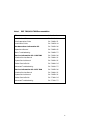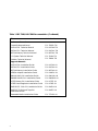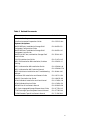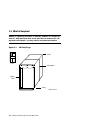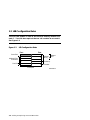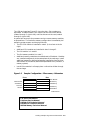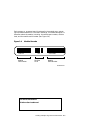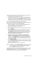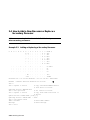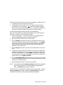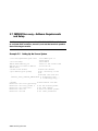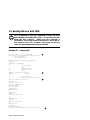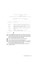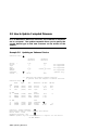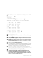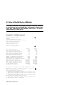
1
DEC 7000 AXP System
VAX 7000
System Service Manual
Order Number EK–7002B–SV.002
This manual tells how to add or replace CPU and memory modules in a
DEC 7000 AXP or VAX 7000 system.
digital equipment corporation
maynard, massachusetts
First Printing, November 1992
The information in this document is subject to change without notice and should
not be construed as a commitment by Digital Equipment Corporation.
Digital Equipment Corporation assumes no responsibility for any errors that may
appear in this document.
The software, if any, described in this document is furnished under a license and
may be used or copied only in accordance with the terms of such license. No responsibility is assumed for the use or reliability of software or equipment that is
not supplied by Digital Equipment Corporation or its affiliated companies.
Copyright © 1992 by Digital Equipment Corporation.
All Rights Reserved.
Printed in U.S.A.
The following are trademarks of Digital Equipment Corporation:
Alpha AXP
AXP
DEC
DECchip
DEC LANcontroller
DECnet
DECUS
DWMVA
OpenVMS
ULTRIX
UNIBUS
VAX
VAXBI
VAXELN
VMScluster
XMI
The AXP logo
dT
OSF/1 is a registered trademark of the Open Software Foundation, Inc.
FCC NOTICE: The equipment described in this manual generates, uses, and may
emit radio frequency energy. The equipment has been type tested and found to
comply with the limits for a Class A computing device pursuant to Subpart J of
Part 15 of FCC Rules, which are designed to provide reasonable protection against
such radio frequency interference when operated in a commercial environment.
Operation of this equipment in a residential area may cause interference, in which
case the user at his own expense may be required to take measures to correct the
interference.
Contents
Preface ..................................................................................................... vii
Chapter 1 Adding or Replacing CPUs and
Memories
1.1
1.2
1.3
1.4
1.5
1.6
What Is Required ................................................................... 1-2
LSB Configuration Rules ....................................................... 1-4
Identifying the Kernel FRUs ................................................ 1-6
Removing a Module from the LSB Card Cage ..................... 1-8
Inserting a Module in the LSB Card Cage ......................... 1-10
Verifying the System ........................................................... 1-12
Chapter 2 Servicing the CPU
2.1
2.2
2.3
2.4
2.5
2.6
2.7
2.8
System Parameters ................................................................ 2-2
How to Replace the Only Processor ...................................... 2-6
How to Replace the Boot Processor ....................................... 2-8
How to Add a New Processor or Replace a Secondary
Processor ............................................................................... 2-10
Build EEPROM Command .................................................. 2-12
FEPROM Recovery—Hardware Requirements ................. 2-14
FEPROM Recovery—Software Requirements and Setup . 2-16
FEPROM Recovery—Procedure .......................................... 2-18
Chapter 3 Updating Firmware
3.1
3.2
3.3
3.4
3.5
Booting LFU on a DEC 7000 System .................................... 3-2
Booting LFU on a VAX 7000 ................................................. 3-4
Show ....................................................................................... 3-6
List .......................................................................................... 3-8
Update .................................................................................. 3-10
iii
3.6
3.7
3.8
3.9
Exit ....................................................................................... 3-12
Display and Verify Commands ............................................ 3-14
How to Update Corrupted Firmware .................................. 3-16
How to Modify Device Attributes ........................................ 3-18
Appendix A Kermit Parameters
Examples
Example 1-1
Example 2-1
Example 2-2
Example 2-3
Example 2-4
Example 2-5
Example 2-6
Example 3-1
Example 3-2
Example 3-3
Example 3-4
Example 3-5
Example 3-6
Example 3-7
Example 3-8
Example 3-9
Self-Test Display ................................................................. 1-12
Replacing a Single Processor ................................................ 2-6
Replacing the Boot Processor ............................................... 2-8
Adding or Replacing a Secondary Processor ...................... 2-10
Build EEPROM Command ................................................. 2-12
Setting Up the Source System ............................................ 2-16
Using Kermit to Downline Load FEPROM Code .............. 2-18
RRD42 LFU Booting ............................................................. 3-2
Booting LFU .......................................................................... 3-4
Show Command ..................................................................... 3-6
List Command ....................................................................... 3-8
Update Command ............................................................... 3-10
Exit Command ..................................................................... 3-12
Display and Verify Commands ........................................... 3-14
Updating an "Unknown" Device ......................................... 3-16
Modify Command ................................................................ 3-18
Figures
Figure 1-1
Figure 1-2
Figure 1-3
Figure 1-4
Figure 1-5
Figure 1-6
Figure 2-1
LSB Card Cage ....................................................................... 1-2
LSB Configuration Rules ....................................................... 1-4
Sample Configuration—2 Processors, 4 Memories ............. 1-5
Module Barcode ...................................................................... 1-7
Removing a Module from the LSB Card Cage ...................... 1-8
Inserting a Module in the LSB Card Cage ......................... 1-10
Sample Hardware Requirements for Remote FEPROM
Recovery ................................................................................ 2-14
Tables
Table 1
iv
DEC 7000/VAX 7000 Documentation ..................................... ix
Table 2
Table 1-1
Table 2-1
Related Documents .................................................................. xi
Field-Replaceable Units ......................................................... 1-6
EEPROM Environment Variables ........................................ 2-2
v
Preface
Intended Audience
This manual is written for Digital customer service engineers and selfmaintenance customers servicing DEC 7000 AXP or VAX 7000 systems.
This manual is a follow-on to Basic Troubleshooting and Advanced
Troubleshooting.
Document Structure
This manual uses a structured documentation design. Topics are organized into small sections for efficient on-line and printed reference. Each
topic begins with an abstract. You can quickly gain a comprehensive overview by reading only the abstracts. Next is an illustration or example,
which also provides quick reference. Last in the structure are descriptive
text and syntax definitions.
This manual has three chapters and one appendix, as follows:
•
Chapter 1, Adding or Replacing CPUs and Memories, describes
how to add or replace these modules.
•
Chapter 2, Servicing the CPU, explains how to restore the system
environment to its state before the changes were made.
•
Chapter 3, Updating Firmware, tells how to make updates to firmware on processor or I/O adapter modules.
•
Appendix A, Kermit Parameters, shows what parameters must be
set for using the Kermit program, which is used in down-line loading
flash ROM code.
vii
Conventions Used in This Document
Terminology. Unless specified otherwise, the use of "system" refers to
either a DEC 7000 AXP or VAX 7000 system. The DEC 7000 AXP systems
use the Alpha AXP architecture. References in text use DEC 7000 to refer
to DEC 7000 AXP systems.
When a discussion applies to only one system, an icon is used to highlight
that system. Otherwise, the discussion applies to both systems. Thus, the
abstract for a module that applies only to DEC 7000 systems would look
like this:
This section shows a sample boot of OpenVMS Alpha AXP
DEC from the RRD42 CD drive for DEC 7000 systems. The first
7000
step is issuing the show device command to determine the
location of the RRD42.
Book titles. In text, if a book is cited without a product name, that book is
part of the hardware documentation. It is listed in Table 1 along with its
order number.
Icons. The icons shown below are used in illustrations for designating part
placement in the system described. A shaded area in the icon shows the
location of the component or part being discussed.
Front
Rear
Documentation Titles
Table 1 lists the books in the DEC 7000 and VAX 7000 documentation set.
Table 2 lists other documents that you may find useful.
viii
Table 1
DEC 7000/VAX 7000 Documentation
Title
Order Number
Installation Kit
EK–7000B–DK
Site Preparation Guide
EK–7000B–SP
Installation Guide
EK–700EB–IN
Hardware User Information Kit
EK–7001B–DK
Operations Manual
EK–7000B–OP
Basic Troubleshooting
EK–7000B–TS
Service Information Kit—VAX 7000
EK–7002A–DK
Platform Service Manual
EK–7000A–SV
System Service Manual
EK–7002A–SV
Pocket Service Guide
EK–7000A–PG
Advanced Troubleshooting
EK–7001A–TS
Service Information Kit—DEC 7000
EK–7002B–DK
Platform Service Manual
EK–7000A–SV
System Service Manual
EK–7002B–SV
Pocket Service Guide
EK–7700A–PG
Advanced Troubleshooting
EK–7701A–TS
ix
Table 1 DEC 7000/VAX 7000 Documentation (Continued)
Title
Order Number
Reference Manuals
Console Reference Manual
EK–70C0B–TM
KA7AA CPU Technical Manual
EK–KA7AA–TM
KN7AA CPU Technical Manual
EK–KN7AA–TM
MS7AA Memory Technical Manual
EK–MS7AA–TM
I/O System Technical Manual
EK–70I0A–TM
Platform Technical Manual
EK–7000A–TM
Upgrade Manuals
x
KA7AA CPU Installation Guide
EK–KA7AA–IN
KN7AA CPU Installation Guide
EK–KN7AA–IN
MS7AA Memory Installation Guide
EK–MS7AA–IN
KZMSA Adapter Installation Guide
EK–KXMSX–IN
DWLMA XMI PIU Installation Guide
EK–DWLMA–IN
DWMBB VAXBI PIU Installation Guide
EK–DWMBB–IN
H7237 Battery PIU Installation Guide
EK–H7237–IN
H7263 Power Regulator Installation Guide
EK–H7263–IN
BA654 DSSI Disk PIU Installation Guide
EK–BA654–IN
BA655 SCSI Disk and Tape PIU
Installation Guide
EK–BA655–IN
Removable Media Installation Guide
EK–TFRRD–IN
Table 2 Related Documents
Title
Order Number
General Site Preparation
Site Environmental Preparation Guide
EK–CSEPG–MA
System I/O Options
BA350 DECstor/me Modular Storage Shelf
Subsystem Configuration Guide
EK–BA350–CG
BA350 DECstor/me Modular Storage Shelf
Subsystem User’s Guide
EK–BA350–UG
BA350-LA DECstor/me Modular Storage Shelf
User’s Guide
EK–350LA–UG
CIXCD Interface User Guide
EK–CIXCD–UG
DEC FDDIcontroller 400 Installation/Problem
Solving
EK–DEMFA–IP
DEC LANcontroller 400 Installation Guide
EK–DEMNA–IN
DEC LANcontroller 400 Technical Manual
EK–DEMNA–TM
DSSI VAXcluster Installation and Troubleshooting
Manual
EK–410AA–MG
InfoServer 150 Installation and Owner’s Guide
EK–INFSV–OM
KDM70 Controller User Guide
EK–KDM70–UG
KFMSA Module Installation and User Manual
EK–KFMSA–IM
KFMSA Module Service Guide
EK–KFMSA–SV
RRD42 Disc Drive Owner’s Manual
EK–RRD42–OM
RF Series Integrated Storage Element User Guide
EK–RF72D–UG
TF85 Cartridge Tape Subsystem Owner’s Manual
EK–OTF85–OM
TLZ06 Cassette Tape Drive Owner’s Manual
EK–TLZ06–OM
xi
Table 2 Related Documents (Continued)
Title
Order Number
Operating System Manuals
Alpha Architecture Reference Manual
EY–L520E–DP
DEC OSF/1 Guide to System Administration
AA–PJU7A–TE
DECnet for OpenVMS Network Management Utilities
AA–PQYAA–TK
Guide to Installing DEC OSF/1
AA–PS2DA–TE
OpenVMS Alpha Version 1.0 Upgrade and
Installation Manual
AA–PQYSA–TE
VMS Upgrade and Installation Supplement:
VAX 7000–600 and VAX 10000–600 Series
AA–PRAHA–TE
VMS Network Control Program Manual
AA–LA50A–TE
VMSclusters and Networking
HSC Installation Manual
EK–HSCMN–IN
SC008 Star Coupler User’s Guide
EK–SC008–UG
VAX Volume Shadowing Manual
AA–PBTVA–TE
Peripherals
Installing and Using the VT420 Video Terminal
EK–VT420–UG
LA75 Companion Printer Installation and User Guide
EK–LA75X–UG
xii
Chapter 1
Adding or Replacing
CPUs and Memories
This chapter provides information on how to remove and install processor
and memory modules in DEC 7000 and VAX 7000 systems. Sections include:
•
What Is Required
•
LSB Configuration Rules
•
Identifying the Kernel FRUs
•
Removing a Module from the LSB Card Cage
•
Inserting a Module in the LSB Card Cage
•
Verifying the System
For information on servicing I/O modules, see the Platform Service Manual; it also describes removal and replacement of the LSB centerplane
and card cage (Part No. 70-28574-01), the IOP module (Part No. E2044AA), and all power system FRUs.
Adding or Replacing CPUs and Memories 1-1
1.1 What Is Required
Adding or replacing processor or memory modules is a simple operation. Afterward you must verify that the new modules are recognized in the system. You may need to set system parameters.
Figure 1-1
LSB Card Cage
Slots
Front
Centerplane
Power
Filter
Slots
BXB-0088A-92
1-2 Adding or Replacing CPUs and Memories
Processor and memory modules reside in the LSB card cage, a centerplane
card cage with nine slots for modules. The LSB card cage always contains
an IOP module, a clock module, and at least one processor and one memory
module (see Figure 1-1).
To add or replace modules, you will follow the steps in Sections 1.2 through
1.6. Then you will:
•
Set system parameters to the original operating environment
(Chapter 2).
•
Upgrade firmware if required (Chapter 3).
For more information:
Basic Troubleshooting
Advanced Troubleshooting
Adding or Replacing CPUs and Memories 1-3
1.2 LSB Configuration Rules
The first CPU module is node 0, and the first memory module is at
node 7. The LSB bus requires that an IOP module be at node 8.
See Figure 1-2.
Figure 1-2
LSB Configuration Rules
Front
Rear
Power Filter
Additional CPUs
or Memories
First CPU
4
Additional
CPUs
Additional
Memory
3
5
2
6
1
7
First Memory
0
8
IOP Module
Centerplane
BXB-0094-92
1-4 Adding or Replacing CPUs and Memories
The LSB card cage (see Figure1-2) has nine slots. Slot numbers are
equivalent to node numbers. Four slots are at the front of the cabinet
(nodes 0 through 3, right to left), and five slots are at the rear (nodes 4
through 8, right to left).
A system can have up to six processors and up to seven memory modules,
as space allows. The maximum memory configuration is bounded by the
operating system support and the physical slots.
•
The first CPU module is installed in node 0 (in the front at the far
right).
•
Additional CPU modules are installed in slots 1 through 5.
•
The IOP module is in node 8.
•
The first memory module is in node 7.
•
Additional memory modules are installed next to filled slots. Modules
are installed contiguously to the centerplane of the card cage. Install
additional memories alternating between installation from the front
and the back of the cabinet (see the example below of a 2 processor, 4
memory system).
•
Install filler modules in all empty slots to direct the airflow through
the card cage.
Figure 1-3
Sample Configuration—2 Processors, 4 Memories
Front
Rear
4
Filler Module
Filler Module
3
5
4th Memory
3rd Memory
2
6
2nd Memory
2nd CPU
1
7
1st Memory
1st CPU
0
8
IOP Module
Centerplane
BXB-0094A-92
For more information:
Platform Service Manual
KN7AA CPU Technical Manual
KA7AA CPU Technical Manual
MS7AA Memory Technical Manual
Adding or Replacing CPUs and Memories 1-5
1.3 Identifying the Kernel FRUs
Table 1-1 lists the field-replaceable units (FRUs) for DEC 7000 and
VAX 7000 systems that are discussed in this book.
Table 1-1
Field-Replaceable Units
Option No.
Part No.
Description
KN7AA
E2040-AA
DEC 7000 CPU module
KA7AA
E2045-AA
VAX 7000 CPU module
MS7AA-AA
E2043-AA
64-Mbyte memory module
MS7AA-BA
E2043-BA
128-Mbyte memory module
MS7AA-CA
E2043-CA
256-Mbyte memory module
MS7AA-DA
E2046-AA
512-Mbyte memory module
Removal and replacement of the LSB centerplane and card cage (Part No.
70-28574-01), the IOP module (Part No. E2044-AA), and all power system
FRUs are described in the Platform Service Manual.
1-6 Adding or Replacing CPUs and Memories
Each memory or processor board is enclosed in the module case, protecting the module electronics from static discharge. A barcode label gives information about the module, including the module part number, revision
level, and the module serial number (see Figure 1-4).
Figure 1-4
Module Barcode
E2043-AA
Module
Part Number
E04
Revision
Level
GAO1234567
Module
Serial Number
BXB-0089-92
For more information:
Platform Service Manual
Adding or Replacing CPUs and Memories 1-7
1.4 Removing a Module from the LSB Card Cage
Use the following procedure to remove a module from the LSB
card cage for replacement or reconfiguration.
Removing a Module from the LSB Card Cage
SGO1234567
Figure 1-5
E 04
2.
E2043-AA
1.
BXB-0090B-92
1-8 Adding or Replacing CPUs and Memories
1.
Perform an orderly shutdown of the system.
2.
Turn the keyswitch on the front control panel to the Disable position
and wait for the control panel yellow Fault LED to stop flashing.
When the Fault LED stops flashing, power has been removed from
the LSB backplane and you may safely proceed.
3.
Open the cabinet door by holding the recessed handhold and pulling it
out toward you.
4.
Put on the antistatic wrist strap.
CAUTION: You must wear a wrist strap when you handle any modules.
5.
Release the plate covering the LSB card cage by loosening the two
thumbscrews on the end of the plate. The plate is connected to the
card cage by a cable; push the plate to one side.
6.
On the module you are removing, use your thumbs to pull the two
black restraining clips out and to the right (see Figure 1-5, step 1).
The clips snap when they open.
7.
Pull both levers out at the same time until they are perpendicular to
the front of the module (see Figure 1-5, step 2). This frees the module
from the backplane.
8.
Holding the levers, pull on the module until it is out far enough to hold
it underneath as you remove it.
9.
When the module becomes free of the card cage, hold it with both
hands, and place the module on an ESD pad in a safe area. If the
module is being replaced, pack the module in the box from the new
module.
For more information:
Platform Service Manual
Adding or Replacing CPUs and Memories 1-9
1.5 Inserting a Module in the LSB Card Cage
Use the following procedure when replacing or adding a module
in the system card cage during maintenance or upgrade.
Figure 1-6
Inserting a Module in the LSB Card Cage
BXB-0091A-92
1-10 Adding or Replacing CPUs and Memories
Follow Steps 1 through 6 in Section 1.4 and then:
1.
If you are adding a module, remove the filler module from the slot
where you will install the new module. Hold the filler module firmly
on the vertical piece closest to you and gently pull it out toward you.
Place it aside for return.
2.
On the module to be inserted, pull out the two black restraining clips
to the right and pull the two levers out until they are perpendicular to
the front edge of the module. The clips snap open.
3.
Pick up the module to be inserted, holding it securely with both hands.
4.
Align the bottom tracks of the module with the tracks in the card cage
slot (see Figure 1-6). Align the top ridge of the module with the track
at the top of the card cage slot.
5.
Holding the module level, gently guide it into the card cage. If you encounter any resistance, check the alignment of the tracks and reinsert.
As the module slides in, release your hand from the corner and guide
the module with two hands as you insert it.
When the module is fully inserted, the front of the module will be flush
with the card cage. Note that the module does not click when it is
fully inserted.
6.
Holding the two metal tabs, push both of them toward the edges of
the module simultaneously. Check that the ends of the metal tabs are
fitting into the guides of the card cage slot (see Figure 1-6). Push the
levers toward the module case.
7.
Snap the black restraining clips across the levers to secure the module.
8.
Check that filler modules are placed in all unused slots.
9.
Replace the plate covering the card cage by tightening the two thumbscrews.
10. Close the cabinet doors.
Adding or Replacing CPUs and Memories 1-11
1.6 Verifying the System
Power up the system and check that all processor and memory
modules appear in the self-test display.
Example 1-1
F
E
.
+
.
.
D
.
.
.
.
C
+
.
.
.
Self-Test Display
B
.
+
.
.
Firmware Rev =
P00>>>
A
.
.
.
.
9
.
.
.
.
8
A
o
.
o
.
+
.
7
M
+
.
+
.
+
.
6
M
+
.
+
.
+
.
5
.
.
.
.
.
.
.
4
.
.
.
.
.
.
.
3
.
.
.
.
.
.
.
2
.
.
.
.
.
.
.
1
P
+
E
+
E
+
E
+
+
.
.
.
.
.
.
+
.
.
.
.
+
.
.
+
.
.
.
.
.
.
.
.
.
.
+
+
.
.
. A1 A0 .
.128 128 .
.
.
.
.
.
.
.
.
V1.0-1625
SROM Rev =
V1.0-0
0
P
+
B
+
B
+
B
NODE #
TYP
ST1
BPD
ST2
BPD
ST3
BPD
C0 XMI +
C1 XMI +
C2
C3
.
.
ILV
256Mb
SYS SN =
1
2
2
2
3
4
GAO1234567
5
BXB-0087-92
1-12 Adding or Replacing CPUs and Memories
Power up the system by turning the keyswitch from Disable to either the
Enable or Restart position. Power sequencing begins and the system runs
self-test. Check the self-test display to make sure that the system recognizes the newly installed modules.
Example 1-1 shows the self-test display of a system in which one processor
and one memory module were added. The newly installed modules are at
nodes 1 and 6, respectively.
1
On the TYP line the P indicates that processors are at nodes 0 and 1.
The M indicates that memory modules are at nodes 6 and 7.
2
The plus signs on the ST lines indicate that the modules passed their
self-tests.
3
Two I/O channels are part of the system, both XMI buses. All adapters connected on the first channel’s XMI passed self-test (see C0 XMI
line). One adapter on the second channel’s XMI failed self-test as indicated by the minus sign (see C1 XMI line).
4
These two lines show the memory interleave set and size.
5
The identification line shows the system firmware revision level and
serial number.
If the primary processor is new to the system, the system serial number will not be shown. You must enter this information, along with
any other system parameters in effect before the processor was
changed. Chapter 2 explains how to set the parameters.
If any processors or memory fail self-test, refer to the appropriate Advanced Troubleshooting manual.
For more information:
Basic Troubleshooting
Advanced Troubleshooting
Adding or Replacing CPUs and Memories 1-13
Chapter 2
Servicing the CPU
This chapter describes how to service a CPU in a DEC 7000 or a VAX 7000
system should it break or should new CPUs be added to a system. Some
CPU firmware problems are covered in this chapter; others are covered in
Chapter 3. Sections in this chapter include:
•
System Parameters
•
How to Replace the Only Processor
•
How to Replace the Boot Processor
•
How to Add a New Processor or Replace a Secondary Processor
•
Build EEPROM Command
•
FEPROM Recovery
—Hardware Requirements
—Software Requirements and Setup
—Procedure
Servicing the CPU 2-1
2.1 System Parameters
Several system parameters must be set during repair or when adding CPUs. Other system parameters may require setting depending upon how the customer wants the system configured.
Table 2-1
EEPROM Environment Variables
Environment
Variable
Default
Value
auto_action
Halt
Specifies the action the system will take following an error halt. Values are:
restart - Automatically restart. If restart
fails, boot the operating system.
boot - Automatically boot the operating system.
halt - Enter console mode.
baud
9600
Sets the console terminal baud rate. Allowable values are 300, 600, 1200, 2400, 4800,
and 9600.
boot_file
Null
The default file name used for the primary
bootstrap when no file name is specified by
the boot command.
boot_osflags
Null
Operating system flags used for booting the
OS in specific ways, if none are specified by
the boot command with the -flags qualifier.
boot_reset
On for
DEC
7000.
Resets system and displays self-test results
during booting. Default is off for VAX 7000.
The default device or device list from which
booting is attempted when no device name is
specified by the boot command.
bootdef_dev
cpu
Variable Description
n
Node ID of the primary (n = 0, 1, 2, 3).
(Table 2-1 continued on page 2-4)
2-2 Servicing the CPU
Table 2-1 shows the permanent environment variables stored in EEPROM.
Some of these variables must be set when either adding a CPU or replacing a broken one. You may view these variables by typing show * at the
console prompt.
Volatile environment variables are initialized by a system reset; others are
nonvolatile across system failures. Environment variables can be created
and modified using the create and set commands, respectively.
The form of the set command is set <envar> <value> and causes the
variable named to be changed in memory and in primary and secondary
EEPROMs. The change takes place immediately.
Servicing the CPU 2-3
Table 2-1 EEPROM Environment Variables (Continued)
Environment
Variable
Default
Value
cpu_enabled
0xff
A bitmask determining which CPUs are
enabled to run (leave console mode). If
not defined, all available processors are
considered enabled.
cpu_primary
0xff
A bitmask indicating which CPUs are eligible to become the primary processor,
following the next system reset. If not
defined, all available processors are considered enabled.
d_harderr
Halt
Determines action taken following a hard
error. Values are halt and continue.
Applies only when using the test command.
d_report
Summary
Determines level of information provided
by the diagnostic reports. Values are
summary and full. Applies only when
using the test command.
d_softerr
Continue
Determines action taken following a soft
error. Values are halt and continue.
Applies only when using the test command.
dump_dev
Null
Device to which dump file is written if
system crashes. (DEC 7000 only)
enable_audit
On
If set to on, enables the generation of
audit trail messages used to track boot to
determine location of boot failure.
interleave
Default
The memory interleave specification.
Value must be default (memory configuration algorithm that attempts to maximize memory interleaving is used),
none, or an explicit interleave list.
language
English
Determines whether system displays
message numbers or message text. Default value is 36 (English).
2-4 Servicing the CPU
Variable Description
Another important environment variable, not shown in Table 2-1, because
it is not a default variable but may be defined by the customer, is a nickname. Should the customer want to have a default boot path for a cluster
and a different local one, a nickname variable may be used for that purpose. Nicknames are set by a console command of the form create -nv
old_disk dua0.0.0.4.0. The -nv option indicates this nonvolatile environment variable will be stored in EEPROM. Once old_disk is so defined,
one can type boot old_disk at the console prompt. Once the environment
variable old_disk has been defined, it can be modified with the set command.
For more information:
Console Reference Manual
Servicing the CPU 2-5
2.2 How to Replace the Only Processor
When replacing the only processor in a system, you must store the
system ID and customized boot paths. If the customer changed
console environment variables from the default values, you will
want to set them as the customer wishes.
Example 2-1
Replacing a Single Processor
>>> show device
# Shows device sizes in the
# system and the path to the
# devices.
polling for units on kzmsa0, slot 3, xmi0...
dka300.3.0.3.0
DKA300
RZ73
dka400.4.0.3.0
DKA400
RZ73
dkb400.4.1.3.0
DKB300
RRD42
>>> set eeprom serial
System Serial Number> GAO1234567 # Enter system serial no.
>>> set bootdef_dev dka400.4.0.3.0 # Sets the default
# boot device.
>>> set boot_osflags 8001,2,0#
#
>>> show *
#
#
Set custom boot flags;
operating system dependent.
Shows the environment
variables.
>>> create -nv old_disk duc1.0.0.11.2
# Setting a possible boot
# path to "old" disks. See
# the Operations Manual for
# details.
>>> set eeprom field
LARS> 01234567
Message>
>>> boot
2-6 Servicing the CPU
#
# Enter LARS number.
# Enter message.
After you have removed and replaced the defective module, following the
instructions in Chapter 1, take the following steps:
1.
Power up the system. Self-test is run and you need to decide whether
the new CPU module is functioning properly. If it is not, try reseating
the new CPU and/or refer to the Advanced Troubleshooting manual;
otherwise continue.
2.
Retrieve the console printout of environment variables, system serial
number, custom boot paths, and any other system-specific configurations saved in the Site Management Guide.
If this information has not been saved, you can find the system serial
number on the barcode at the back of the system cabinet on the surface just below the AC input box. Details on boot paths and changed
console environment variables you will need to get from the system
manager.
3.
Once you have collected the data you need, enter the console commands shown in Example 2-1 that you need. For example, you may
or may not need to use the show device command, which sizes the
system and can be used to see what devices are available. The fields
after the device name indicate the path to the device and are necessary when specifying the bootdef_dev environment variable.
a. You will definitely need to set the system serial number.
b. You will definitely need to set the bootdef_dev.
c. For example, you may need to set the boot_osflags depending
upon the operating system used and how the system manager normally boots the system.
d. If you have a list of environment variables from the Site Management Guide, you will want to compare it against the output given
by the show * command. If there are differences, you will want to
change the variables using commands similar to those that follow.
e. You may need to set one or more special boot paths depending
upon how the system manager configures the system.
4.
Once the console environment is set up, verify the repair by booting
the system. If there are alternative boot paths, you will want to make
sure that all boot paths function properly.
5.
Use the set eeprom field command to enter the 8-digit LARS number
and a short message (up to 68 characters), stating the date and reason
for service, into the EEPROM.
6.
Boot the system and return control to the customer.
Servicing the CPU 2-7
2.3 How to Replace the Boot Processor
In cases where the boot processor in a multiprocessing system is
the CPU that is in need of repair, you need to manipulate which
CPU receives data from the console terminal.
Example 2-2
Replacing the Boot Processor
F
E
D
C
B
A
9
8
A
o
.
o
.
+
.
7
M
+
.
+
.
+
.
6
.
.
.
.
.
.
.
5
.
.
.
.
.
.
.
4
.
.
.
.
.
.
.
3
.
.
.
.
.
.
.
2
.
.
.
.
.
.
.
1
P
+
E
+
E
+
E
.
.
.
.
.
.
.
.
.
.
.
.
.
.
.
.
+
.
.
.
.
.
.
.
+
.
.
.
.
.
.
.
+
.
.
.
.
.
.
.
.
.
.
.
.
.
.
.
+
.
.
.
.
.
.
.
. A0
.128
.
.
.
.
.
.
.
.
.
.
.
.
0
P
+
B
+
B
+
B
NODE #
TYP
ST1
BPD
ST2
BPD
ST3
BPD
C0 XMI +
C1
C2
C3
.
.
ILV
128Mb
Firmware Rev = V2.0-1234 SROM Rev = V1.0-0 SYS SN = GAO1234567
KN7AA1: Firmware Revision Mismatch V1.0-1625
2
P00>>>
P00>>> set cpu kn7aa1
P01>>> update -e kn7aa0
Updating kn7aa0’s EEPROM done
P01>>> set cpu kn7aa0
P00>>> update -f kn7aa1
# Set console to kn7aa1
# Copy customized EEPROM envars
# from kn7aa1 to kn7aa0.
# Copy flash ROM from kn7aa0
# to kn7aa1
Update kn7aa1’s FLASH ROMs [Y/(N)]? y
Updating kn7aa1’s FLASH ROMs ...done
P00>>> set eeprom field
#
LARS> 01234567
# Enter LARS number.
Message>
# Enter message.
P00>>> boot
2-8 Servicing the CPU
There are at least two factors to consider when replacing a primary CPU:
1.
The desire to retain the system environment.
2.
The possibility that the new CPU is at a higher or lower firmware revision than other CPUs in the system. 2 shows the mismatch message should the firmware differ between CPUs. Note that in this case
the newer primary has a higher firmware revision than the secondary.
The procedure described here takes these into consideration.
After you have removed and replaced the defective primary CPU following
the instructions in Chapter 1, take the following steps:
1.
Power up the system. If self-test fails, refer to the appropriate Advanced Troubleshooting manual; otherwise continue.
2.
Note the firmware revision of the new CPU.
3.
Use the set cpu command to connect the console terminal to another
CPU in the system.
4.
Use the update -e command to copy the EEPROM environment variables from the secondary processor to the new primary processor.
(The update -e command copies the system serial number and other
parameters that can be set, as well as any additional information
stored in the EEPROM to the target CPU.)
5.
If there is a firmware revision mismatch, you should update the
FEPROMs on the older CPUs. To do this, run the console on the
newer CPU. Use the set cpu command to get to the newer version
and then use the update -f command. Note that if there are several
CPUs that need updating, you can use a wildcard to target them all,
as in update -f kn7aa*.
6.
Use the set eeprom field command to enter the 8-digit LARS number
and a short message (up to 68 characters), stating the date and reason
for service, into the EEPROM.
7.
Boot the system and return control to the customer.
NOTE: If the customer used the set cpu_primary command to change the
default which allows all CPUs in the system to become the primary, the set cpu command may not work.
To allow all CPUs in the system to become the primary processor, use the
set cpu_primary ff command. Modify the cpu_primary environment
variable to the customer setting after performing the updates.
Servicing the CPU 2-9
2.4 How to Add a New Processor or Replace a
Secondary Processor
Add a new secondary in the slot to the left of the boot processor or
other secondary processors.
Example 2-3
Adding or Replacing a Secondary Processor
F
E
D
C
B
A
9
8
A
o
.
o
.
+
.
7
M
+
.
+
.
+
.
6
.
.
.
.
.
.
.
5
.
.
.
.
.
.
.
4
.
.
.
.
.
.
.
3
.
.
.
.
.
.
.
2
.
.
.
.
.
.
.
1
P
+
E
+
E
+
E
.
.
.
.
.
.
.
.
.
.
.
.
.
.
.
.
+
.
.
.
.
.
.
.
+
.
.
.
.
.
.
.
+
.
.
.
.
.
.
.
.
.
.
.
.
.
.
.
+
.
.
.
.
.
.
.
. A0
.128
.
.
.
.
.
.
.
.
.
.
.
.
0
P
+
B
+
B
+
B
NODE #
TYP
ST1
BPD
ST2
BPD
ST3
BPD
C0 XMI +
C1
C2
C3
.
.
ILV
128Mb
Firmware Rev = V1.0-1625 SROM Rev = V1.0-0 SYS SN = GAO1234567
KN7AA1:
Firmware Revision Mismatch V2.00-1234
2
P00>>>
P00>>> update -e kn7aa1
Updating kn7aa1’s EEPROM done
P00>>> set cpu kn7aa1
P01>>> update -f kn7aa0
# Copy customized EEPROM envars
# from kn7aa0 to kn7aa1.
# Set console to kn7aa1.
# Copy flash ROM from kn7aa1 to
# kn7aa0.
Update kn7aa0’s FLASH ROMs [Y/(N)]? y
Updating kn7aa0’s FLASH ROMs ...done
P01>>> set eeprom field
LARS> 01234567
# Enter LARS number.
Message>
# Enter message.
P01>>> boot
2-10 Servicing the CPU
There are at least two factors to consider when adding or replacing a CPU:
1.
The desire to retain the system environment.
2.
The possibility that the new CPU is at a higher firmware revision
than other CPUs in the system. 2 shows the mismatch message
should the firmware differ between CPUs. In this case the newer secondary has a higher firmware revision than the older primary.
The procedure described here takes these into consideration.
After you have removed and replaced the defective CPU following the instructions in Chapter 1, take the following steps:
1.
Power up the system. If self-test fails, refer to the appropriate Advanced Troubleshooting manual; otherwise continue.
2.
Note the firmware revision of the primary CPU.
3.
Use the update -e command to copy the EEPROM environment variables from the primary processor to the new secondary. (The update
-e command copies the system serial number and other parameters
that can be set, as well as any additional information stored in the
EEPROM to the target CPU.)
4.
Use the set cpu command to connect the console terminal to the new
CPU.
5.
If there is a firmware revision mismatch, you will want to update the
FEPROMs on the older CPUs. Since you are already running the console from the newest CPU, use the update -f command. Note that if
there are several CPUs that need updating, you can use a wildcard to
target them all, as in update -f kn7aa*.
6.
Use the set eeprom field command to enter the 8-digit LARS number
and a short message (up to 68 characters), stating the date and reason
for service, into the EEPROM.
7.
Boot the system and return control to the customer.
NOTE: If the customer used the set cpu_primary command to change the
default which allows all CPUs in the system to become the primary, the set cpu command may not work.
To allow all CPUs in the system to become the primary processor, use the
set cpu_primary ff command. Modify the cpu_primary environment
variable to the customer setting after performing the updates.
Servicing the CPU 2-11
2.5 Build EEPROM Command
Should the EEPROM become corrupted, you can use the build
eeprom command to recover. The build eeprom command is the
proper response to the console error messages shown in Example
2-4. If the build eeprom command fails, return the module for repair.
Example 2-4
Build EEPROM Command
EEPROM image failed to verify
#Checksum bad.
EEPROM environment parameters not set up #Ev area corrupt.
Fail to update EEPROM envar on CPU x
#Cannot write
#EEPROM.
P00>>> build eeprom
Creating new EEPROM image
System Serial Number>
# Enter system serial number.
Module Serial Number>
# Enter module serial number.
Module Unified 2-5-2-4 Part Number> # Enter part number.
Module Firmware Revision> # Enter 0.00
#
P00>>> set cpu kn7aa1
# Move to the next CPU should
# more than one be corrupt.
P01>>> build eeprom
Creating new EEPROM image
System Serial Number>
# Enter system serial number.
Module Serial Number>
# Enter module serial number.
Module Unified 2-5-2-4 Part Number> # Enter part number.
Module Firmware Revision> # Enter 0.00
#
P01>>> initialize
2-12 Servicing the CPU
Should an EEPROM become corrupted, the error message, EEPROM image failed to verify, is printed. Should this occur, use the build eeprom
command to rebuild the EEPROM. When the EEPROM is rebuilt, all settings will revert to default settings. Follow Section 2.2 to customize environment variables.
The build eeprom command prompts you for several pieces of information. You can find this information in the following locations:
•
The system serial number is on the barcode at the back of the system
cabinet on the surface just below the AC input box.
•
The 10-digit module serial number is the last number on the barcode
found on the module itself. See Figure 1-4.
•
Most of the module unified 2-5-2-4 part number can also be found on
the barcode. The first number is 80, the second for the DEC 7000 is
E2040 and for the VAX 7000 is E2045, the third is a two-letter module
variant, like AA, and the fourth is the hardware revision. A valid 2-52-4 part number is:
80-E2045-AA-0E04
The dashes should be entered when responding to the prompt.
•
The module firmware revision number cannot be determined in the
field. A proper response to the prompt is 0.00.
If the EEPROM image fails to rebuild, send the module back for repair.
Once the image has been rebuilt, use the initialize command to set the
environment variables to the default values. Customize the system, if necessary, using the set and create commands.
For more information:
Console Reference Manual
Servicing the CPU 2-13
2.6 FEPROM Recovery—Hardware Requirements
When FEPROMs are corrupt and you do not have a CPU to use the
update -f command, you may be able to recover the console and diagnostic code through the console terminal line. A serial line receive program in the serial ROM forces a prompt, AXP- or VAX7000/10000-FRRC>, on the console terminal.
Figure 2-1
Sample Hardware Requirements for Remote FEPROM
Recovery
InfoServer
Source VAX
Ethernet
DEMNA
DMB32
7000 System
RS232
Cable
RRD42
(DEC 7000 only)
Console
Port
BXB-0005G-92
2-14 Servicing the CPU
There are three methods for recovering console and diagnostic code. The
first is to use the update -f command; the second is to use the Loadable
Firmware Update (LFU) Utility; and the third is to downline load the console/diagnostic firmware into the damaged system and copy it into the
FEPROMs. The use of the update -f command can only be done in a multiprocessing system and is documented in Sections 2.3 and 2.4. LFU can
be used when the console is completely functioning and is described in
Chapter 3. The third method, the least desirable, is described here.
Other pertinent information follows:
•
The console terminal must be set at 9600 baud for the AXP-/VAX7000/10000-FRRC> prompt to appear.
•
On site or remote access to the system is required.
•
The procedure may take 20 to 30 minutes to complete if there are no
line problems.
What you need is:
•
An independent source system that can logically connect to the damaged system through the console line. The system can be on site or remote. You do not need a DMB32 as shown in Figure 2-1, but you need
some hardware mechanism to connect to the target’s console port.
•
The source system must have access to an RRD42 or an InfoServer.
•
The software program Kermit must reside on the source system.
•
The AXP/VAX 7000 Console CD-ROM, with the console/diagnostic
code on it. The file name for the console/diagnostic code is
AXP7000_10000_CONSOLE_IMAGE.GROM for the DEC 7000 system
and VAX7000_10000_CONSOLE_IMAGE.GROM for the VAX 7000
system.
The serial line receive program in the serial ROM of the CPU is called
FRRC (FEPROM recovery code). Its function is to receive and store data
sent down the console line.
Servicing the CPU 2-15
2.7 FEPROM Recovery—Software Requirements
and Setup
On the source system you need to "bind" the RRD42 or InfoServer
to a virtual disk container, mount it, and set the terminal speed to
that of the target console.
Example 2-5
Setting Up the Source System
$ set term/speed=9600/perm txa3:
#
#
#
#
#
$ mcr ess$ladcp
LADCP> BIND VAX7000_V01
VAX7000_V01 is bound to DAD104
LADCP> exit
$ mount/ov=id dad104
#
$ dir dad104:[sys0.sysexe]
#
.
#
.
#
VAX7000_10000_CONSOLE_IMAGE.GROM
.
$ Kermit
Kermit-32>
Kermit-32>
Kermit-32>
Kermit-32>
Kermit-32>
Set DMB32 port to
9600 baud.
Run LADCP.
This is the volume label
from the CD.
Mount the CD-ROM.
Get a directory of the
CD.
Desired file name will
# be AXP7000_10000_...
# or VAX7000_10000_...
# Enter Kermit from DCL.
set file type binary
set retry packet 5
set send time 5
show all
set xxx
2-16 Servicing the CPU
#
#
#
#
Set max retries/packet.
Set send timeout.
Shows all Kermit params.
Set other parameters.
Example 2-5 illustrates the steps needed to prepare Kermit with
OpenVMS VAX. What you do is:
1.
First make sure that you have the hardware necessary to perform the
task.
2.
Make sure you have the correct CD-ROM for the damaged system.
3.
Set the terminal speed on the source system to 9600. FRRC only
works at 9600 baud.
4.
Run LADCP at the source system to "bind" the CD-ROM volume name
to a virtual disk container pointed to by a logical name created by
LADCP.
5.
Next, set the correct parameters for Kermit. Example 2-5 shows how
to run Kermit from a DCL prompt and gives examples of setting the
parameters. The show all command produces a list of Kermit parameters that should be compared to the parameters shown in Appendix A.
6.
Set all parameters in accordance with Appendix A.
Servicing the CPU 2-17
2.8 FEPROM Recovery—Procedure
After Kermit has been set up and you are ready to downline load
the file, AXP or VAX7000_10000_CONSOLE_IMAGE.GROM, connect
to the target system, prepare it to receive the file and then load it.
The final steps are to copy the file into the FEPROMs and boot the
system. Note that all commands are entered on the source system.
Example 2-6
Using Kermit to Downline Load FEPROM Code
Kermit-32> connect txa5:
# Line = com path e.g., TXA5
[should now get a FRRC> prompt on remote terminal]
VAX-7000/10000-FRRC> r
Ctrl/] C
# Type FRRC receive command.
# Escape sequence to return
# to Kermit.
Kermit-32> send
dad104:[SYS0.SYSEXE]VAX7000_10000_CONSOLE_IMAGE.GROM
[Type Ctrl/A to get a brief status update]
[Kermit responds OK when finished]
Kermit-32> status
Kermit-32> connect
# To get a status report.
# To reconnect to FRRC on the
# target system.
VAX-7000/10000-FRRC> c
VAX-7000/10000-FRRC> p
#
#
#
#
VAX-7000/10000-FRRC> i
To verify checksum of image.
To copy program image into
FEPROMs.
To reset node.
VAX-7000/10000-FRRC> Ctrl/]C # Escape sequence to return
# to Kermit.
Kermit-32> exit
# To return to DCL.
$
2-18 Servicing the CPU
Assuming you have the correct CD-ROM in an InfoServer, you are now
ready to connect to the damaged target system and downline load the
code. Example 2-6 illustrates a VAX 7000 recovery. Follow the same
steps for the DEC 7000, using the AXP7000_10000_console_image.grom
file.
1.
At the Kermit prompt, connect to the target system. Here are two examples of connections:
connect txa5:
Logically connect to the target console line
connect lta1004: Logically connect to the target console line
2.
Once connected to the console, make the target system ready to receive the code by typing r (for receive) at the VAX-7000/10000-FRRC>
prompt on the source system.
3.
Return to Kermit on the source system by typing Ctrl/ ] C.
4.
Downline load the console and diagnostic code by using the Kermit
send command. Here are several examples to help you with the location and name of the file:
send dadx:[sys0.sysexe]vax7000_10000_console_image.grom
send dua0:[directory_name]vax7000_10000_console_image.grom
If the file was copied to a disk earlier.
5.
Once the code has been downline loaded, reconnect to the target.
6.
Issue the following three VAX-7000/10000-FRRC> commands:
c
causes the checksum to be verified for the code just loaded.
p
clears and then writes the code into the FEPROMs.
i
resets the system. The console prompt on the target system
should appear and the flash ROM repair should be complete.
7.
Return to Kermit on the source system by typing Ctrl/ ] C.
8.
Exit Kermit.
Servicing the CPU 2-19
Chapter 3
Updating Firmware
Use the Loadable Firmware Update (LFU) Utility to update system firmware. LFU runs without any operating system and can update the firmware on any system module. LFU handles modules on the LSB bus (for
example, the CPU) as well as modules on the I/O buses (for example, a CI
controller on the XMI bus). You are not required to specify any hardware
path information, and the update process is highly automated.
Both the LFU program and the firmware microcode images it writes are
supplied on a CD-ROM. You start LFU on DEC 7000 systems by booting
the RRD42. On VAX 7000 systems, you start LFU by booting the
InfoServer on your Ethernet.
A typical update procedure is:
1.
Boot the LFU CD-ROM.
2.
Use the LFU show command to indicate modules whose firmware
needs to be updated.
3.
Use the LFU list command if you want to check the firmware version
numbers on the CD-ROM.
4.
Use the LFU update command to write the new firmware.
5.
Exit.
Sections in this chapter are:
•
How to Boot LFU
•
Show
•
List
•
Update
•
Exit
•
Display and Verify Commands
•
How to Update Corrupted Firmware
•
How to Modify Device Attributes
Updating Firmware 3-1
3.1 Booting LFU on a DEC 7000 System
LFU is supplied on the DEC 7000/10000 AXP Console CDDEC ROM (Part Number AG-PQW3*-RE, where * is the letter
7000
that denotes the disk revision). Make sure this CD-ROM is
mounted in the RRD42 in-cabinet CD drive. Boot LFU from
the CD-ROM.
Example 3-1
RRD42 LFU Booting
>>> show device
1
polling for units
dka100.1.0.1.0
polling for units
dub1.1.0.6.0
dub2.2.0.6.0
>>> boot dka100
Booting...
on kzmsa, slot 1, xmi0...
dka100
RRD42
on kfmsb0, slot 6, xmi0...
R2TDYC$DIA1
RF73
R2TDYC$DIA2
RF73
2
Copyright Digital Equipment Corporation
1992
All Rights Reserved.
Loadable Environment Rev: V1.0-1625
Jul 12 1992
10:50:56
***** Loadable Firmware Update Utility *****
Version 2.01
16-jun-1992
------------------------------------------------------------------Function
Description
------------------------------------------------------------------Display
Exit
List
Displays the system’s configuration table.
Return to loadable offline operating environment.
Lists the device types and firmware revisions
supported by this revision of LFU.
Modify
Modifies port parameters and device attributes.
Show
Displays device mnemonic, hardware and firmware
revisions.
Update
Replaces current firmware with loadable data
image.
Verify
Compares loadable and device images.
? or Help
Scrolls the function table.
------------------------------------------------------------------Function?
3-2 Updating Firmware
3
1
Use the show device command to find the name of the RRD42 CD
drive.
2
Enter the boot command to boot from the RRD42. The RRD42 has a
device name of dka100.
3
LFU starts, displays a summary of its commands, and issues its
prompt (Function?).
Updating Firmware 3-3
3.2 Booting LFU on a VAX 7000
LFU is supplied on the VAX 7000/10000 Console CD-ROM
VAX (Part Number AG-PQW1*-RE, where * is the letter that de7000
notes the disk revision).
Make sure this CD-ROM is
mounted in one of the system’s InfoServers. Boot the Initial System Load (ISL) program, and select the service
name corresponding to the console CD-ROM.
Example 3-2
Booting LFU
>>> boot exa0 -file ISL_LVAX_V01
Resulting file is mopdl:ISL_LVAX_V01/exa0
...... Load complete!
[boot information]
Network Initial System Load Function
Version 1.1
FUNCTION
FUNCTION
ID
1
Display Menu
2
Help
3
Choose Service
4
Select Options
5
Stop
Enter a function ID value: 3
OPTION
OPTION
ID
1
Find Services
2
Enter known Service Name
Enter an Option ID value: 1
1
2
3
Working
Servers found:: 3
Service Name Format:
Service Number
Service Name
Server Name
Ethernet ID
#1
INFO4$RZ57
INFO4
08-00-2B-26-A6-98
#2
6000_DIAG_H
INFO3
08-00-2B-16-04-D4
#3
VAX7000_V01
OPUS_ESS
08-00-2B-18-A9-75
Enter a Service Number or <CR> for more: 3
3-4 Updating Firmware
4
Copyright Digital Equipment Corporation
1992
All Rights Reserved.
Loadable Environment Rev: V1.0-1625
Jul 12 1992 10:50:56
***** Loadable Firmware Update Utility *****
Version 2.01
16-jun-1992
------------------------------------------------------------------Function
Description
------------------------------------------------------------------Display
Exit
List
Displays the system’s configuration table.
Return to loadable offline operating environment.
Lists the device types and firmware revisions
supported by this revision of LFU.
Modify
Modifies port parameters and device attributes.
Show
Displays device mnemonic, hardware and firmware
revisions.
Update
Replaces current firmware with loadable data
image.
Verify
Compares loadable and device images.
? or Help
Scrolls the function table.
------------------------------------------------------------------Function?
5
1
Enter the boot command to boot from the InfoServer. Note that the
ISL file name must be typed in upper case. The final two characters
are the ISL file version, which you can read from the last two characters of the volume label printed on the CD-ROM.
2
Enter 3, to select Choose Service from the Function menu.
3
Enter 1 to select Find Services from the Option menu.
4
Enter the number of the service named VAX7000_Vnn. This service
name is the volume label printed on the CD-ROM. In this example,
service number 3 supplies the console CD-ROM.
5
LFU starts, displays a summary of its commands, and issues its
prompt (Function?).
Updating Firmware 3-5
3.3 Show
The show command shows the current revision of firmware and
hardware for every module in the system that contains microcode.
In the display, each module that needs to be updated is indicated
by a plus sign (+) following the device mnemonic.
Example 3-3
Show Command
1
Function? show
2
Device Mnemonic(s)? ?
-------------------------------------------------------------------Valid Device
Entries
Selected function is:
-------------------------------------------------------------------Device Mnemonic#
performed to a single device.
Device Mnemonic*
performed to all devices of the same type.
* or All
performed to all devices in the system.
Exit
not performed. Program returns to Selection
prompt.
-------------------------------------------------------------------3
Device Mnemonic(s)? exit
4
Function? sho *
Firmware
Revision
kn7aa0
ms7aa0
iop0
xmi0
kdm700
demna0
demfa0
kfmsb0
cixcd0
kzmsa0
+
+
1.00
---3.00
6.08
-5.06
69.00
5
Hardware
Revision
E04
---Cannot be read
Cannot be read
-a04
A01
not supported.
not supported.
not supported.
not supported.
’+’ indicates the update firmware revision
is greater than the adapter’s firmware revision.
Function?
3-6 Updating Firmware
1
If you type just the command show without a device mnemonic, LFU
prompts for the device mnemonic. All the commands that require device mnemonics will prompt.
2
If you enter ? (or help) for the device, a table displays the syntax for
specifying devices. All the commands that require device specifications
use this syntax. Note the use of wildcards. For example,
show kdm70* would display all KDM70 controller modules.
3
If you enter an exit command at the device prompt, LFU returns to
the function prompt for another command.
4
The most useful form of the command is show * which displays every
module in the system. Note in this example that the CPU and CIXCD
modules require updating. (In other words, the + means that the firmware version on the CD-ROM is higher than the version on the module.)
5
VAX 7000 systems do not support kn7aa, kfmsb, and kzmsa. The following devices show up in the display instead:
ka7aa0
kfmsa0
+
1.10
E04
5.06
A04
Updating Firmware 3-7
3.4 List
The list command displays the inventory of update firmware on
the CD-ROM. Only the devices listed at your terminal are supported for firmware updates.
Example 3-4
List Command
Function? l 1
Loadable Firmware Update Utility
Version 2.01 2
Name
Mnemonic
Update Firmware
Revision
CIXCD
cixcd*
70.00
KDM70
kdm70*
3.00
All Revisions
KN7AA
kn7aa*
1.01
All Revisions
KZMSA
kzmsa*
2.00
All Revisions
Function?
3-8 Updating Firmware
Update Hardware
Revision
A01
-
A01
1
The list command shows the revisions of firmware corresponding to
the revisions of hardware for each device. (There may be several hardware revisions for a particular device, but only one firmware revision
corresponds to any hardware revision.) Comparing the output of the
list and show commands helps you understand which devices should
receive firmware updates.
2
VAX 7000 systems do not support kn7aa and kzmsa. The following devices show up in the display instead:
KA7AA
KFMSA
ka7aa*
kfmsa*
1.10
5.06
4.00
All Revisions
A02 - A01
All Remaining
Revisions
Updating Firmware 3-9
3.5 Update
The update command writes new firmware from the CD-ROM to
the module. Then LFU automatically verifies the update by reading the new firmware image from the module back into memory
and comparing it with the CD-ROM image.
Example 3-5
Function?
Update Command
update kn7aa0 cixcd0
1
2
Update kn7aa0? [Y/(N)] y
WARNING: updates may take several minutes to complete for each device.
DO NOT ABORT!
Updating to 1.10... Reading Device... Verifying 1.10...PASSED. 3
kn7aa0
4
Update cixcd0? [Y/(N)] y
WARNING: updates may take several minutes to complete for each device.
DO NOT ABORT!
cixcd0
Updating to 70.00... Reading Device... Verifying 70.00... PASSED.
5
Function? update *
Name
Type
Rev
Mnemonic
KN7AA
MS7AA
IOP
(8002)
(4000)
(2000)
0000
0000
0001
kn7aa0
ms7aa0
iop0
C0 XMI
8+
DWLMA
E+
DEMNA
(102A)
(0C03)
A5A6
060B
xmi0
dwlma0
demna0
LSB
0+
7+
8+
Update ALL devices? [Y/(N)] y
FW Rev
1.00
N/A
N/A
N/A
6.08
HW Rev
E04
A01
A
A
6
WARNING: updates may take several minutes to complete for each device.
DO NOT ABORT!
kn7aa0
ms7aa0
iop0
xmi0
demna0
Updating to 1.10... Reading Device... Verifying 1.10...PASSED
not supported.
not supported.
not supported.
firmware rev is greater or equal to update rev.
3-10 Updating Firmware
7
Continue? [Y/(N)] y
WARNING: updates may take several minutes to complete for each device.
DO NOT ABORT!
demna0
Updating to 6.06... Reading Device... Verifying 6.06... PASSED.
Function? update demna*
8
Update all demna?
[Y/(N)] n
Function?
9
1
This command specifically requests firmware updates for the CPU and
CIXCD modules. Note the syntax of a device list, separated by
spaces.
2
LFU requires you to confirm each update, if you named the modules
specifically.
3
Status message reports update and verification progress.
4
LFU prompts for each device in turn.
5
This is a second example. When you specify the * wildcard, LFU tries
to update all devices.
6
LFU prints the configuration table and prompts before all devices are
updated.
7
This message appears because, in this example, the firmware on the
DEMNA module is not at a lower revision level than the firmware image on the CD-ROM. You can still request LFU to perform the update.
If the module version is equal to the update firmware, you may have
previously tried the update (making the module and CD-ROM firmware images the same revision). However, if the verification process
had reported an error, you can repeat the update. Also, this feature
allows you to update a module with an older revision of firmware.
8
This is another example, using a wildcard to request LFU to update all
DEMNA adapters in the system.
9
When you use a device mnemonic followed by the wildcard, LFU
prompts once for all devices of the same type.
CAUTION: Never abort an update operation; you will corrupt the firmware on the module.
Updating Firmware 3-11
3.6 Exit
The exit command terminates the LFU program, causes system initialization and self-test, and returns to the system console
prompt.
Example 3-6
Function?
Exit Command
show
Device Mnemonic(s)?
1
exit
2
Function? exit
Initializing...
F
E
D
C
B
A
9
8
A
o
.
o
.
+
.
7
M
+
.
+
.
+
.
6
.
.
.
.
.
.
.
5
.
.
.
.
.
.
.
4
.
.
.
.
.
.
.
3
.
.
.
.
.
.
.
2
.
.
.
.
.
.
.
1
P
+
E
+
E
+
E
.
.
.
.
.
.
.
.
.
.
.
.
.
.
.
.
+
.
.
.
.
.
.
.
+
.
.
.
.
.
.
.
+
.
.
.
.
.
.
.
.
.
.
.
.
.
.
.
+
.
.
.
.
.
.
.
0
P
+
B
+
B
+
B
NODE #
TYP
ST1
BPD
ST2
BPD
ST3
BPD
C0 XMI +
C1
C2
C3
. A0 . . . . . . . ILV
.128 . . . . . . . 128Mb
Firmware Rev = V1.0-1625 SROM Rev = V1.0-0 SYS SN = GAO1234567
P00>>>
3-12 Updating Firmware
3
1
From within the "Device Mnemonic(s)?" prompt, exit returns to the
Function prompt.
2
At the Function prompt, exit causes the system to be initialized.
3
The console prompt appears.
Updating Firmware 3-13
3.7 Display and Verify Commands
Display and verify commands are used in special situations.
Display shows the physical configuration. Verify repeats the verification process performed by the update command.
Example 3-7
Function? disp
Name
LSB
0+
KN7AA
5+
MS7AA
7+
MS7AA
8+
IOP
Display and Verify Commands
1
Type
Rev
Mnemonic
(8002)
(4000)
(4000)
(2000)
0000
0000
0000
0001
kn7aa0
ms7aa0
ms7aa1
iop0
1.00
N/A
N/A
N/A
E04
A01
A01
A
C0 XMI
8+
DWLMA
C+
KDM70
E+
DEMNA
(102A)
(0C22)
(0C03)
A5A6
1E11
060B
xmi0
dwlma0
kdm700
demna0
N/A
3.00
6.08
A
C1 XMI
1+
?????
8+
DWLMA
A+
CIXCD
(0000)
(102A)
(0C05)
0000
A5A6
EB11
xmi1
unknown0
dwlma1
cixcd0
N/A
69.00
Function? verify kdm700
FW Rev
HW Rev
A
A01
2
kdm700 Reading Device... Verifying 3.00... FAILED.
At Address 3d830 3 Hardware data 41570020 Update data
At Address 3d834 Hardware data 4E494E52 Update data
At Address 3d838 Hardware data 54203A47 Update data
At Address 3d844 Hardware data 65696620 Update data
At Address 3d848 Hardware data 7420646C Update data
At Address 3d84c Hardware data 20747365 Update data
At Address 3d988 Hardware data 69662020 Update data
At Address 3d98c Hardware data 00646C65 Update data
At Address 3d998 Hardware data 73657420 Update data
At Address 3d99c Hardware data 65722074 Update data
3-14 Updating Firmware
20200020
20202020
54202020
20202020
302E3356
20202020
20202020
00202020
20202020
65722020 4
1
Display shows the system physical configuration. Display is equivalent to issuing the console command show configuration. Because it
shows the LSB slot for each module, display can help you identify unknown devices.
2
Verify reads the firmware from the module into memory and compares it with the update firmware on the CD-ROM. If a module already verified successfully when you updated it, but later failed selftest, you can use verify to tell whether the firmware has become corrupted.
3
The address displayed for a failed compare is relative to the beginning
of the update firmware image.
4
Verify terminates after 10 comparisons fail.
Updating Firmware 3-15
3.8 How to Update Corrupted Firmware
If LFU identifies a device as unknown, the firmware on the module is corrupted. The update command allows you to specify the
correct device type so that new firmware can be written to the
module.
Example 3-8
Updating an "Unknown" Device
Function? sho * 1
Firmware
Revision
kn7aa0
+
ms7aa0
iop0
xmi0
kdm700
demna0
unknown0
cixcd0
+
2
1.00
---3.00
--69.00
Hardware
Revision
E04
---Cannot be read
--A01
not supported.
not supported.
not supported.
not supported.
Updates only.
’+’ indicates the update firmware revision
is greater than the adapter’s firmware revision.
3
Function? disp
Name
Type
Rev
Mnemonic
KN7AA
MS7AA
IOP
(8002)
(4000)
(2000)
0000
0000
0001
kn7aa0
ms7aa0
iop0
1.00
N/A
N/A
E04
A01
A
C0 XMI
8+
DWLMA
C+
KDM70
E+
DEMNA
(102A)
(0C22)
(0C03)
A5A6
IE11
060B
xmi0
dwlma0
kdm700
demna0
N/A
3.00
6.08
A
C1 XMI
1+
?????
8+
DWLMA
A+
CIXCD
(0000)
(102A)
(0C05)
0000
A5A6
EB11
xmi1
unknown0
dwlma1
cixcd0
LSB
0+
7+
8+
FW Rev
HW Rev
4
N/A
69.00
A
A01
Function: update unknown0
5
Enter device name or ’exit’ to skip this device.
Device name? cixcd
6
Hardware revision? A01
7
WARNING: updates may take several minutes to complete for each device.
DO NOT ABORT!
3-16 Updating Firmware
unknown0
8
Updating to 70.00... Reading Device... Verifying 70.00... PASSED.
Function? exit
9
Initializing...
F E D C B A 9 8 7 6
[self-test map appears]
. A0 .
.128 .
Firmware Rev = V1.0-1625 SROM
>>> sho config
Name
Type
LSB
0+
KN7AA
(8002)
7+
MS7AA
(4000)
8+
IOP
(2000)
5
4
3
2
1
0
NODE #
. . . . . . ILV
. . . . . . 128Mb
Rev = V1.0-0 SYS SN = GAO1234567
Rev
Mnemonic
0000
0000
0001
kn7aa0
ms7aa0
iop0
C0 XMI
8+
DWLMA
C+
KDM70
E+
DEMNA
(102A)
(0C22)
(0C03)
A5A6
IE11
060B
xmi0
dwlma0
kdm700
demna0
C1 XMI
1+
CIXCD
8+
DWLMA
A+
CIXCD
(0C05)
(102A)
(0C05)
EB11
A5A6
EB11
xmi1
cixcd0
dwlma1
cixcd1
10
1
Issue the show command.
2
The display indicates an unknown device — LFU is unable to recognize device type.
3
Issue the display command. Then you can identify the unknown device by looking at the physical configuration.
4
Display shows that the unknown device is in slot 1 of the second XMI
bus. You inspect the module and identify it as a second CIXCD with
hardware revision A01.
5
Issue the command update unknown0.
6
LFU prompts you for only the device name (not mnemonic). The mnemonic is the device name plus a unique number which is assigned by
the system. The device name in this example is cixcd.
7
If the device has several hardware versions supported by different
firmware images, LFU prompts you for the hardware version so that it
will be updated with the correct firmware image.
8
Status message indicates that the update succeeded.
9
To make the device known, initialize the system by exiting LFU.
10
Initialization has made the device known to the system. The previously unknown device is now assigned device mnemonic cixcd0 by the
system. The previous cixcd0 is now cixcd1.
Updating Firmware 3-17
3.9 How to Modify Device Attributes
The modify command can change parameters stored in EEPROM
on the following devices: KZMSA (DEC 7000 system), KFMSA (VAX
7000), DEC LANcontroller 400 (DEMNA), and CIXCD. The attributes are specific to each device.
Example 3-9
Modify Command
1
Function? modify cixcd0
cixcd0
Current Hardware rev is E03
Modify Module Hardware Rev? [Y/(N)]y
Enter new Hardware Rev:e04
Are you sure? [Y/(N)]y
Updating Hardware rev
2
Function? modify kfmsa0
XPC Interrupt Vector:
XPC Control Register Mask:
XPC Interrupt Priority Level:
Real-time Clock Timeout Period:
DSSI Initiator Timeout Period:
DSSI Target Timeout Period:
DSSI Selection Timeout Period:
Number of Immediate DSSI Retries:
Number of Delayed DSSI Retries:
Maximum number of Coin-flips:
Idle Counter for Immediate Retries:
DSSI Retry Initial Seed:
XMI Transaction Timeout Value:
XMI Lockout Assertion Value:
XMI Lockout Deassertion Value:
CP Bus Timeout Value:
Secondary Lock Retries:
Port 1
0400
0000
06
9D
2C
27
15
0008
0100
000A
0000
A7524B79
0003D810
000003E8
00007A12
0000E66D
0020
Port 2
0400
0000
06
9D
2C
27
15
0008
0100
000A
0000
A7524B79
0003D810
000003E8
00007A12
0000E66D
0020
Do you wish to modify any of these parameters? [Y/(N)]y
3
Which Port (1=port 1, 2=port 2, 3=both) ? [1-3(1)]1
Modify CP Bus parameters? [Y/(N)]y
4
XPC Interrupt Vector? [(0400)]
Enter new value (HEX) or <CR> to keep present value:
XPC Control Register Mask? [(0000)]
Enter new value (HEX) or <CR> to keep present value:
XPC Interrupt Priority Level? [(06)]
Enter new value (HEX) or <CR> to keep present value:
Real-time Clock Timeout Period? [(9D)]
Enter new value (HEX) or <CR> to keep present value:
CP Bus Timeout Value? [(0000E66D)]
3-18 Updating Firmware
Enter new value (HEX) or <CR> to keep present value:
Secondary Lock Retries? [(0020)]
Enter new value (HEX) or <CR> to keep present value:
Modify DSSI Timeouts? [Y/(N)]n
4
Modify DSSI Retries? [Y/(N)]n
4
Modify XMI Timeouts? [Y/(N)]n
4
Finished display/modify parameters? [(Y)/N]y
Function? m demna0
5
demna0
Remote Boot:
Remote Console:
Local Console:
Monitor Facility:
Promiscuous Mode:
Log Selftest Errors:
Log NI RBD Errors:
Log XMI RBD Errors:
Log XNA RBD Errors:
Diagnostic Error Logging:
Error Frame Overflow:
ENABLED
ENABLED
ENABLED
ENABLED
ENABLED
ENABLED
ENABLED
ENABLED
ENABLED
DISABLED
ENABLED
Console Password:
XNABOARD
Module Serial Number:
*SG909T1455*
Do you wish to modify any of these parameters?[y/(n)]y
Remote Boot:
Remote Console:
Local Console:
Monitor Facility:
Promiscuous Mode:
Log Selftest Error:
Log NI RBD Errors:
Log XMI RBD Errors:
Log XNA RBD Errors:
Diagnostic Error Logging:
Error Frame Overflow:
ENABLED
ENABLED
ENABLED
ENABLED
ENABLED
ENABLED
ENABLED
ENABLED
ENABLED
DISABLED
ENABLED
Change?
Change?
Change?
Change?
Change?
Change?
Change?
Change?
Change?
Change?
Change?
[y/(n)]y
[y/(n)]
[y/(n)]
[y/(n)]
[y/(n)]
[y/(n)]
[y/(n)]
[y/(n)]
[y/(n)]
[y/(n)]
[y/(n)]
Modify demna0 with these parameter values?[y/(n)]y
6
Remote Boot:
Remote Console:
Local Console:
Monitor Facility:
Promiscuous Mode:
Log Selftest Errors:
Log NI RBD Errors:
Log XMI RBD Errors:
Log XNA RBD Errors:
Diagnostic Error Logging:
Error Frame Overflow:
DISABLED
ENABLED
ENABLED
ENABLED
ENABLED
ENABLED
ENABLED
ENABLED
ENABLED
DISABLED
ENABLED
Console Password:
XNABOARD
Module Serial Number:
*SG909T1455*
Updating Firmware 3-19
1
The CIXCD has only one parameter: the hardware revision. You
would need to modify the value only if the EEPROM had become corrupted.
2
When you modify the KFMSA, LFU first displays all the parameters
for both ports.
3
You select which port to modify.
4
LFU prompts for parameters by category.
5
LFU displays the DEMNA parameters.
6
This example modifies one parameter, disabling remote booting.
For more information:
KFMSA Module Installation and User Manual
CIXCD Interface User Guide
DEC LANcontroller 400 Technical Manual
3-20 Updating Firmware
Appendix A
Kermit Parameters
To transmit a file using Kermit, the following parameters must be set:
Kermit-32> show all
VMS Kermit-32 version 3.3.111
Block check type
One character checksum
Debugging
OFF
Delay
5 (sec)
Server sends NAKs every 75 seconds while waiting for a
command
Escape character
035 (octal)
File type
BINARY
File naming
Normal form
Handshaking character
None
Incomplete file disposition
Discard
Line used
(Optional)
Local echo
OFF
Parity type
None
Retry maximums
Initial connection
Sending a packet
5 (dec)
5 (dec)
Send parameters
Packet length
Padding length
Padding character
Time out
End of line character
Quoting character
Start of packet
80 (dec)
0 (dec)
000 (octal)
5 (sec)
015 (octal)
043 (octal)
001 (octal)
Receive parameters
Packet length
Padding length
Padding character
Time out
80 (dec)
0 (dec)
000 (octal)
5 (sec)
Kermit Parameters A-1
End of line character
Quoting character
015 (octal)
043 (octal)
8-bit quoting character
Start of packet
046 (octal)
001 (octal)
Transmit parameters
Delay
Echo
Repeat quoting character
A-2
Kermit Parameters
0.0 (sec)
OFF
176 (octal)
Index
A
Attributes, setting device, 3-18,
3-19
B
Booting
DSSI VAXcluster, 3-2
LFU, 3-2
Build eeprom command, 2-12
software requirements, 2-16
FEPROM recovery code, 2-15
Field-replaceable units, 1-6
Firmware
corrupted, 3-16
Firmware revision of CPU, 2-9
Firmware
updating, 3-1
FRU part numbers, 1-6
I
C
Configuration rules, LSB, 1-4
Console CD-ROM
part number AG-PQW1*-RE, 3-4
part number AG-PQW3*-RE, 3-2
Console commands
build eeprom, 2-12
create, 2-6
set eeprom serial, 2-6
update -e, 2-8, 2-10
update -f, 2-8, 2-10
D
Device mnemonic, LFU, 3-6
Display command, LFU, 3-14
E
Environment variables, 2-2
Exit command, LFU (1), 3-12
F
FEPROM recovery
hardware requirements, 2-14
procedure, 2-18
InfoServer, 2-15, 3-1, 3-4
Initialize command, 2-13
Initial system load (ISL) file, 3-5
K
Kermit program
example, 2-18
parameters needed, A-1
L
LFU, 3-1
List command, LFU, 3-8
LSB card cage, 1-2
LSB configuration rules, 1-4
M
Modify command, LFU, 3-18
Module barcode label, 1-7
Module installation procedure, 1-10
Module removal procedure, 1-8
N
Nickname, setting, 2-5
Index-1
R
Replace
boot processor, 2-8
only processor, 2-6
secondary processor, 2-10
RRD42, 2-15, 2-16, 3-1, 3-3
S
Self-test display, 1-12
Set CPU command, 2-9
Set eeprom serial command, 2-6
Show command, LFU, 3-6
Show device command, 2-7
System parameters, how to set, 2-2
U
Update command, 2-9
Update command, LFU, 3-10
V
Verification, 1-2, 2-2
Verify command, LFU, 3-14
Index-2