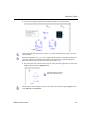
1
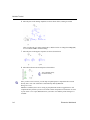
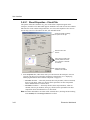
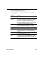
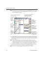
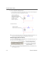
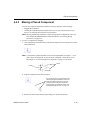
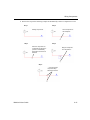
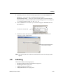
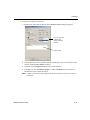
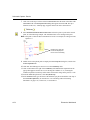
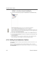
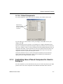
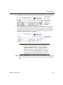
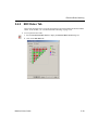
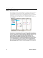
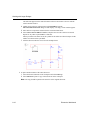
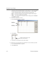
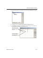
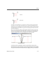
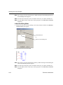
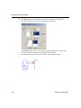
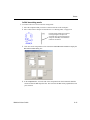
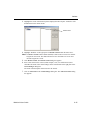
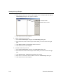
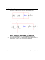
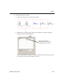
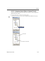
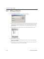
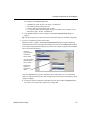
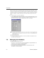
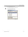
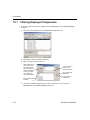
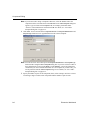
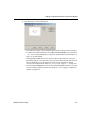
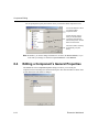
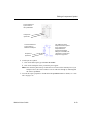
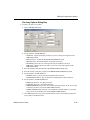
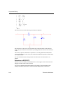
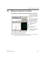
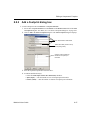
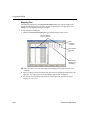
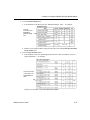
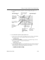
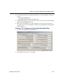
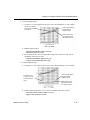
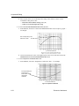
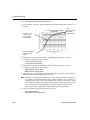
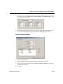
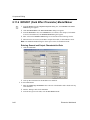
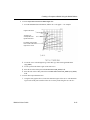
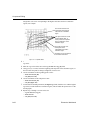
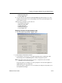
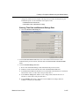
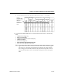
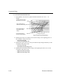
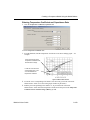
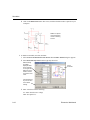
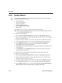
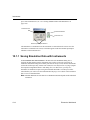
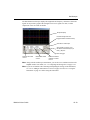
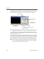
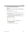
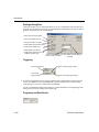
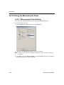
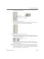
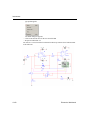
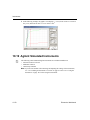
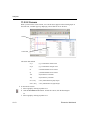
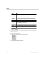
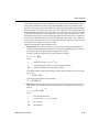
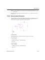
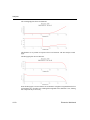
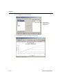
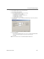
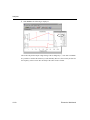
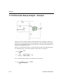
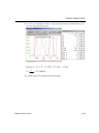
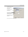
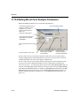
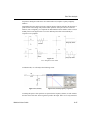
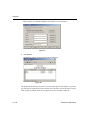
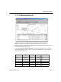
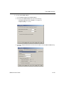
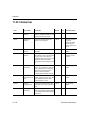
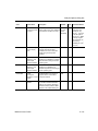
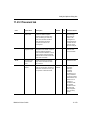
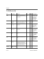
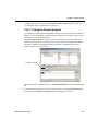
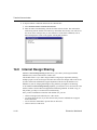
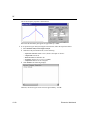
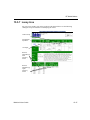
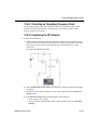
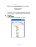
Creating a Component Model Using the Model Makers
To enter DC Current Gain (hFE) at base Temperature data:
1. Among the hFE vs. Ic curves at the base temperature for the BJT, select the one whose
Vce is most likely the operating point for the transistor. For example:
Select a
point to
represent
the
intermediate
DC Current
Gain in the
low Ic
region.
The fourth curve from top
is the hFE vs. Ic curve at
base temperature (Vce =
1V)
Point corresponding to
maximum DC Current
Gain
Point
corresponding to
minimal DC
Current
Gain
Ic value for point
corresponding to
0.5 of maximum
gain in the low Ic
region (see “
Entering “On”
Voltages and
Current-Gain
Bandwidth Data”
on page 8-73).
Point corresponding to 0.5
of the maximum DC Current
Gain in the low Ic region
Ic value for point
corresponding to maximum
gain (see “ Entering “On”
Voltages and Current-Gain
Bandwidth Data” on
page 8-73).
Point
corresponding to 0.5
of the
maximum
DC Current
Gain in the
high Ic
region
Note You must select a curve with the same voltage as the Ic-Vbe curve you will use to enter
data on the last tab of this dialog box. See “ Entering “On” Voltages and Current-Gain
Bandwidth Data” on page 8-73.
2. Find the point on the curve corresponding to the minimal collector current, or the
beginning point of the curve. Use the coordinates of this value to enter:
• DC Current Gain (hFE1)
• Minimal Collector Current
3. Select a point from the low Ic region of the same curve. Use the coordinates of this point
to enter:
• DC Current Gain (hFE2)
• Intermediate Collector Current (low values range)
4. Find the highest point on the curve, and enter its DC Current Gain value in the Max Value
of DC Current Gain (hFE_Max) field.
Multisim 9 User Guide
8-71