1
RF
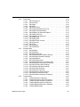
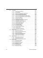
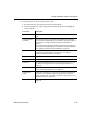
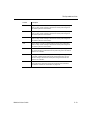
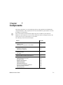
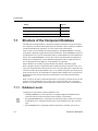
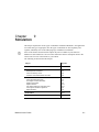
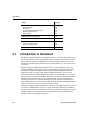
15.1
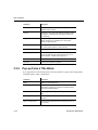
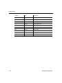
Subject
Page No.
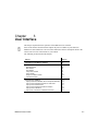
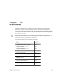
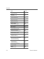
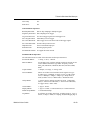
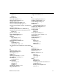
Tutorial: Designing RF Circuits
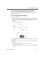
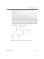
Selecting Type of RF Amplifier
Selecting an RF Transistor
Selecting a DC-operating Point
Selecting the Biasing Network
15-39
15-40
15-40
15-41
15-41
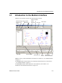
Introduction to the Multisim RF Module
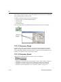
The Multisim RF module is intended to provide fundamental RF circuit design features
needed by engineers to design, analyze and simulate RF circuits.
The Multisim RF module is made up of the following:
• RF-specific components, including customized RF SPICE models
• model makers for creating your own RF models
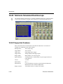
• two RF-specific instruments (Spectrum Analyzer and Network Analyzer)
• several RF-specific analyses (circuit characterizer, matching network cells, noise figure).
Elements of the RF Design module are fully integrated into Multisim. That is, the instruments,
analyses and components are installed in the same places and invoked in the same way as all
other instruments, analyses and components. You will not see a separate access to the RF
Design Module in Multisim’s interface. Instead, for example, the RF components have their
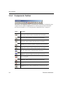
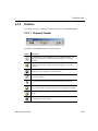
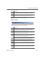
own group which is accessed via the RF button on the Component toolbar and the RF
instruments are accessed through the Instruments toolbar.
15.2
Components
15.2.1 About RF Components
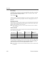
Components in the electronics field fall into two categories — “lumped” components and
“distributed” components. Lumped components are smaller than the wavelength, where:
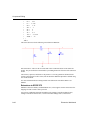
c
λ = -f
In these cases, the wavelength of the voltages and currents at which they are operating is
significantly larger than the components themselves. Ohm's Law, in this case, is valid. For
example, a 1/4 Watt resistor is about 0.270 inch long and 0.090 inch in diameter.
15-2
Electronics Workbench