1
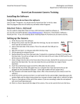
SCINOMIX SCI-PRINT MP2+ USER MANUAL 2 Revision History Revision History Revision 1.2.2.1001 A Date Notes 04/2014 New feature: ability to scan existing barcode and replicate label Enhancements to config screens to include barcode scanner diagnostic. Bug fix for door open message box, Compare of Code39, config screen display. (Reference Release Notes 1.2.2.1001 for more detail) 09/2014 THIS APPLICATION IS NOT BACKWARDS COMPATIBLE. Enhancements to Scan to Print functionality for multi-side printing and using scanned barcode as text source, hardware changes to smart motor, Pre-Run screen updated, no plate found logic change, Stacker and Coney Diagnostic updates, Stacker graphics update, upstack plate counting revised. See Release Notes for various bug fixes See Release Notes for 2 remaining Known Issues (software does not support older versions of hardware and is not compatible with older versions of firmware) Scinomix SCI-PRINT MP2+ User Manual 2000-085 Rev. A Scinomix Sci-Print MP2+ User Manual 2000-085 Rev. A 2 3 General Information General Information The information contained in this document is subject to change without notice. Information provided by Scinomix is believed to be accurate and reliable. However, the user is responsible for the proper and correct use of the product. If the user does not follow the instructions given in this manual, Scinomix does not take any responsibility for injuries or damages caused by the Scinomix product. Instrument Information Manufacturer: Scinomix, Inc Model Number: 1046 SCI-PRINT MP2+ Serial Number: _________________ Contact Scinomix, Inc 4069 Wedgeway Court Earth City, MO 63045 USA Telephone: 314-298-9800 Fax: 314-298-8111 Internet: www.scinomix.com Before operating the instrument, the user must read and understand this manual. Installation and Servicing Only Scinomix service personnel or an authorized distributor shall perform installation, servicing and reinstallation of the instrument. Table of Contents Revision History .......................................................................................................................................... 2 Scinomix Sci-Print MP2+ User Manual 2000-085 Rev. A 3 4 Table of Contents Revision ........................................................................................................................................................ 2 Date............................................................................................................................................................... 2 Notes............................................................................................................................................................. 2 General Information .................................................................................................................................... 3 Table of Contents ......................................................................................................................................... 3 Chapter 1. Introduction ............................................................................................................................. 7 Hardware Overview ................................................................................................................................ 7 Description......................................................................................................................................... 10 System Requirements ....................................................................................................................... 10 Power Requirements ........................................................................................................................ 10 Air Requirements .............................................................................................................................. 10 Communication Requirements......................................................................................................... 10 Operating Environment .................................................................................................................... 10 Health and Safety................................................................................................................................... 11 Important Note .................................................................................................................................. 11 Intended Use ...................................................................................................................................... 11 Personal Protective Equipment (PPE) ............................................................................................. 11 Transport and Storage ...................................................................................................................... 11 Lifting Points ...................................................................................................................................... 11 External Covers.................................................................................................................................. 11 Electrical Safety ................................................................................................................................. 11 Safety Features .................................................................................................................................. 12 Installation ......................................................................................................................................... 12 Noise Levels ....................................................................................................................................... 12 Service and Maintenance .................................................................................................................. 12 Symbols on Equipment ..................................................................................................................... 12 Chapter 2. Startup.................................................................................................................................... 13 Connecting the Sci-Print MP2+ ............................................................................................................ 13 Air ....................................................................................................................................................... 13 Power ................................................................................................................................................. 13 RS232 ................................................................................................................................................. 13 Starting the Sci-Print MP2+ .................................................................................................................. 13 Scinomix Sci-Print MP2+ User Manual 2000-085 Rev. A 4 5 Table of Contents Adjusting the Scinomix Sci-Print MP2+ Grip Force ............................................................................ 15 Plate Orientation ................................................................................................................................... 17 Chapter 3. Plate Configuration ................................................................................................................ 18 Overview ................................................................................................................................................ 18 Plate Configuration Editor Options ...................................................................................................... 18 Plate Height ........................................................................................................................................ 20 Stacker to Use ..................................................................................................................................... 21 Stack Capacity .................................................................................................................................... 21 Grip Height ......................................................................................................................................... 21 Chapter 4. Label Design........................................................................................................................... 23 Overview ................................................................................................................................................ 23 Defining Label Stock .............................................................................................................................. 23 Defining Label Text and Print Layout .................................................................................................. 24 Chapter 5. Creating a Run ....................................................................................................................... 27 Overview ................................................................................................................................................ 27 Description- ....................................................................................................................................... 28 Plate Name- ........................................................................................................................................ 28 Run Params-....................................................................................................................................... 28 Label Preview .................................................................................................................................... 28 New Run Instructions ........................................................................................................................... 28 Run Parameters ..................................................................................................................................... 29 Overview ............................................................................................................................................ 29 Exporting and Post Process Script Options ..................................................................................... 29 Worklists ............................................................................................................................................ 29 Plate Name ......................................................................................................................................... 31 Print Side ............................................................................................................................................ 31 Label Name ........................................................................................................................................ 31 Validate Barcode................................................................................................................................ 31 Label1, Label2, Label3 (and so on) .................................................................................................. 31 User Interface .................................................................................................................................... 33 Scan to Print Option .......................................................................................................................... 35 Pre-run Summary .............................................................................................................................. 37 Scinomix Sci-Print MP2+ User Manual 2000-085 Rev. A 5 6 Table of Contents Chapter 6: Maintenance ............................................................................................................................ 45 Overview ................................................................................................................................................ 45 Printer .................................................................................................................................................... 45 Loading Labels from a Roll ............................................................................................................... 45 Loading Ribbon.................................................................................................................................. 46 Cleaning the Print Head .................................................................................................................... 47 Chapter 7. Hardware and Utilities Diagnostics ..................................................................................... 48 Overview ................................................................................................................................................ 48 Printer Hardware .................................................................................................................................. 48 Outputs ............................................................................................................................................... 49 Inputs ................................................................................................................................................. 49 Stage Actions...................................................................................................................................... 49 Printer Actions................................................................................................................................... 49 Serial Communication ....................................................................................................................... 49 Stacker Hardware .................................................................................................................................. 50 Utilities ................................................................................................................................................... 51 Printer Utilities .................................................................................................................................. 51 Stacker Utilities.................................................................................................................................. 53 Barcode Diagnostics .............................................................................................................................. 55 Application Information ....................................................................................................................... 56 Appendix .................................................................................................................................................... 57 Scinomix Sci-Print MP2+ User Manual 2000-085 Rev. A 6 Chapter 1. Introduction Hardware Overview Please review the following diagrams and familiarize yourself with the terminology used. Front View 8 Chapter 1. Introduction MP2+ Rear View Scinomix Sci-Print MP2+ User Manual 2000-085 Rev. A 8 9 Chapter 1. Introduction Printer Unit Control Panel-Zoom View Scinomix Sci-Print MP2+ User Manual 2000-085 Rev. A 9 10 Chapter 1. Introduction Description The Sci-Print MP2+ is an automated bench top plate labeler integrated with input and output stackers. Up to 48 plates can be loaded and labeled in a single run. Plates that have been manually loaded in the input stackers are unstacked, conveyed to the printing platform, and then moved to the output stackers. Labels can be applied to any and all sides of a microtiter plate. The Sci-Print MP2+ will also print and apply labels to deep well blocks. System Requirements Windows 7 with Service Pack 1, or Windows 8 or 8.1 (recommended) OR Windows XP with Service Pack 3, Microsoft.NET Framework 3.5 with Service Pack 1 or greater Power Requirements 110VAC @3A 240VAC @1.5A Air Requirements 80 PSI @ 1 CFM Communication Requirements The Sci-Print MP2+ connects to a computer via an RS232 serial port. A serial port or USB-serial port adaptor is required on the computer. Operating Environment Indoor use only Temperature: 10°C to 40°C Humidity: 20 to 80% non-condensing Altitude: Up to 2000M Mains supply: +/- 10% Rated Voltage Transient overvoltage: Installation Category (Overvoltage category) II Rated pollution: Pollution degree 2 Scinomix Sci-Print MP2+ User Manual 2000-085 Rev. A 10 11 Chapter 1. Introduction Health and Safety Important Note Before using the equipment, it is very important that you have read this manual and have understood all the safety instructions. Intended Use The Sci-Print MP2+ is intended for use in laboratory settings under the environmental conditions listed above. The equipment is not designed to operate in a potentially explosive environment or to be used with any flammable liquids. If the equipment is used in a manner not specified by the manufacturer, the protection provided by the equipment may be impaired. Plates must be free of defects; any cracked or damaged plates should be replaced before using the Sci-Print MP2+. Personal Protective Equipment (PPE) The Sci-Print MP2+ does not require the use of any special PPE. However, the user should adhere to any PPE standard in the laboratory in which the Sci-Print MP2+ is installed. Transport and Storage The equipment must be stored and transported in temperatures within the range -25C to +55C. Lifting Points The equipment is to be lifted by 2 people. External Covers Warning – If any of the external covers on the equipment are removed the power supply is not automatically interrupted. If it is necessary to remove any of the external covers it is essential that the power is switched off first. Do not attempt to use the equipment until the covers are replaced. Electrical Safety The equipment must be connected to a properly earthed power outlet to protect users from the risk of electric shock. The main chassis of the machine is earthed together with all associated electrical components. Do not remove any of the fixed covers, as there are no user serviceable parts inside. All internal work should be referred to Scinomix service personnel. Scinomix Sci-Print MP2+ User Manual 2000-085 Rev. A 11 12 Chapter 1. Introduction Safety Features The clear conveyor door on the Sci-Print MP2+ is equipped with a locking system that stops motor movement when the doors are opened. Ensure that all doors are closed before beginning any runs. If a door is opened during a run, it must be closed and the user must click on the “Press to Continue” button in the software to resume operation. Installation The Sci-Print MP2+ should be installed on a flat, smooth benchtop clear of obstructions. Installation of the instrument should only be carried out by a Scinomix Service Technician. Noise Levels During normal operation the level of airborne noise emitted by the robot will not exceed 70db measured at a distance of 1 meter. Service and Maintenance It is strongly recommend that maintenance be carried out regularly by a Scinomix-approved service engineer. Symbols on Equipment Symbol Meaning Beware moving parts. Refer to Equipment Manual for operating instructions. 20XX The year of manufacture is given on the serial number label which is located on the side of the unit. Scinomix Sci-Print MP2+ User Manual 2000-085 Rev. A 12 13 Chapter 2. Startup Chapter 2. Startup Connecting the Sci-Print MP2+ Air Connect the air on the back side of the instrument by pushing the blue air line into the air input. Test the connection by pulling on the air line; if you feel resistance, the air line is properly connected. (To remove the air line, gently push on the white outer ring of the air input and pull on the air line). The other end of the air line should be connected to the air source. Ensure that the air is turned on by moving the blue air switch to the horizontal “ON” position (the air switch is located on the right side of the machine, near the bottom of the label applicator arm). Check that the air pressure is sufficient by noting the pressure on the pressure gauge on the side of the base unit of the Sci-Print MP2+. Adjust the pressure as needed using the regulator on the back panel of the SciPrint MP2+ controller. Note: The air pressure gauge measures pressure in Megapascals (MPa), see Appendix 1 for conversion to Pounds per Square Inch. Power Make sure that the power switch is in the OFF position (O). Connect the power cable to the SciPrint MP2+, and then plug in to an appropriate socket. Turn on the power to the instrument by clicking the power switch to the ON position (I). RS232 Connect the RS232 cable to the port on the back of the Sci-Print MP2+, and then connect the other end to the computer. If the computer you are using does not have a serial port, you will need to use a serial-USB adaptor. Starting the Sci-Print MP2+ First check the following items - Your computer is connected to the Sci-Print MP2+ using RS232 The Sci-Print MP2+ has an air supply attached The Sci-Print MP2+ power button is on Double click on the Sci-Print MP2+ icon on the desktop to open the Sci-Print MP2+ software: Scinomix Sci-Print MP2+ User Manual 2000-085 Rev. A 13 14 Chapter 2. Startup The following screen will appear: At this point the software is attempting to communicate with the device. The main screen will appear when the device is ready. Other options include: - Stop waiting and shut down - Run in simulation mode. Plates, labels, and runs can be created and edited in simulation mode but communication to the device is unavailable; therefore the instrument does not move in response to commands - Attempt a different com port Scinomix Sci-Print MP2+ User Manual 2000-085 Rev. A 14 15 Chapter 2. Startup Adjusting the Scinomix Sci-Print MP2+ Grip Force On the front of each Scinomix Sci-Print MP2+ Stacker Module is a grip force adjuster. This adjusts the pressure of the gripper fingers when they hold plates in the stacker. The grip force will be set initially upon installation by a Scinomix technician, but it may need to be adjusted from time to time. To access the grip force adjuster screw, pull off the small round screw cover. The set screw is adjusted using a 2mm Allen wrench. Turning the screw clockwise will decrease the pressure; counterclockwise will increase it. On the back of each Scinomix Sci-Print MP2+ Stacker Module is a “Grip Force Adjust” knob. This knob is obsolete and should not be used. Scinomix Sci-Print MP2+ User Manual 2000-085 Rev. A 15 16 Chapter 2. Startup Scinomix Sci-Print MP2+ User Manual 2000-085 Rev. A 16 17 Chapter 2. Startup Plate Orientation The Sci-Print MP2+ can print on any of the four sides of a plate. For orientation purposes, the side of the plate that faces the printer as it is presented from the stacker is denoted as the “North” side. The “North” and “South” sides are the two short sides of the plate, while “East” and “West” are the two long sides of a plate. (Note that Plexiglas cover has been removed for the purposes of the picture) For example, if a user wishes to print and apply a label to the “A1” side of the plate, then “A1” should be to the back and to the right in the stacker, and printing to the “North” side should be enabled. For optimum labeling, every plate in the stacker should be loaded in the same orientation. Scinomix Sci-Print MP2+ User Manual 2000-085 Rev. A 17 18 Chapter 3. Plate Configuration Chapter 3. Plate Configuration Overview The Sci-Print MP2+ can accommodate many different plate styles. Every plate that is used must first be defined within the plate configuration editor. If you are using micro titer plates with lids, your device will include the optional lid lift accessory. If your instrument does not have the optional lid lift accessory, some of the screenshots below may vary slightly, i.e. lid lift features will not be displayed. Plate Configuration Editor Options From the Configuration Menu, select “Plate Definitions” to access the plate configuration menu: The plate configuration STAGE tab will be displayed: To optimize the print height (in the 9-10mm range for standard 96 well plates), place a plate on the stage and click “Test Print” to print and apply a label to the plate. Use the jog steps to refine Scinomix Sci-Print MP2+ User Manual 2000-085 Rev. A 18 19 Chapter 3. Plate Configuration this position as needed. (Editing for pickup angle and pickup height is disabled when using stackers). Note: Scinomix can provide settings for several different plate types as needed. Click on “NEW” to create a new plate. A text box will prompt you for a name for the new plate: Type in a name for the plate and click “OK”. The plate description is also entered by the user and may provide additional details about the type of plate being used. NEXT: Click on the STACKER tab to display the configuration screen for the stacker: Scinomix Sci-Print MP2+ User Manual 2000-085 Rev. A 19 20 Chapter 3. Plate Configuration Plate Height This is a measured value expressed in millimeters. It is generally 1-2 mm less than the height of the plate specified by the plate manufacturer because it must take into account the way different plate types “nest” when stacked. For example, a plate with a height of 14mm may have a stack height of 13mm. Use the following instructions to calculate plate height: For Non-Lidded Plates: Stack two plates on top of each other, then measure the height from the bottom of the bottom plate to the bottom of the top plate (Note: Some plate manufacturers include “stack height” in their technical specifications. That number can be used instead of performing this measurement): Scinomix Sci-Print MP2+ User Manual 2000-085 Rev. A 20 21 Chapter 3. Plate Configuration For Lidded Plates: To measure the plate height, stack two plates on top of each other. Measure the height of the two stacked plates using a caliper, then divide by 2 to determine the plate height. Stacker to Use This option allows the user to select the stacker to use when teaching a new plate. Plates only need to be taught on one stacker. Generally the down stack is used, but the up stack can also be used based on the accessibility of the stackers and positioning of the instrument in your lab. (If your instrument has multiple stackers, teaching is only allowed on one stacker). Stack Capacity This refers to the maximum number of plates that may be placed in the input or output stacker in a given run. It is automatically calculated and displayed as the plate height changes. If the plates have lids, click the This checkbox will be present on the screen under “plate properties” if your instrument has the optional lid lift accessory. Click the checkbox if you are using plates with lids. Grip Height This is a taught position. The grip height refers to the area where the fingers of the MP2+ grip the plates in the stacker. When a plate is being unstacked from the stacker, the fingers hold the plate directly above the plate being unstacked. For most standard plates, the grip height will be set at 29.5 and should not be altered. For lidded plates, non-skirted plates, or plates of varying flexibility, the grip location will vary. Before teaching the grip height, ensure that the MP2+ is Scinomix Sci-Print MP2+ User Manual 2000-085 Rev. A 21 22 Chapter 3. Plate Configuration homed . Select the jog distance and then click “Jog Up” or “Jog Down” to move the grippers. (It is advisable to begin with a larger jog distance and then switch to a smaller jog distance as the grippers near the desired grip height). Click the “Close Gripper” checkbox to clamp the fingers to the plate. Use the Unstack and Stack buttons to test the accuracy of the grip height; the plates should unstack and stack smoothly. When the plate settings are complete, click on “OK” to save the plate data. Plate configuration settings can also be copied or deleted as necessary by selecting those options at the top of the Plate Configuration Screen. Note: Scinomix can provide settings for several different plate types as needed. Scinomix Sci-Print MP2+ User Manual 2000-085 Rev. A 22 23 Chapter 4. Label Design Chapter 4. Label Design Overview The MP2+ can be set up to run print jobs on a variety of user-named label stocks. Each is set up to support best print quality based on size, material, stiffness, and adhesion. A label editor is provided to enter the properties of a label stock. Defining Label Stock To use the label editor, go to the configuration menu on the Main Screen, then select “Label Stock” The Label Stock Editor Screen will be displayed: This screen allows the user to define the physical characteristics of the label being used, including the length of the label, the width of the label, and the span of the label (i.e. the distance from the Scinomix Sci-Print MP2+ User Manual 2000-085 Rev. A 23 24 Chapter 4. Label Design leading edge of one label to the leading edge of the next label). See the image below for label measurement definitions: For most microplates, the label size is set at ¼” length and 2” width. The margins, peel off speed and distance, and heat settings can also be adjusted. Once any desired changes are made, Click OK to save or Cancel to cancel without saving. You can also create a new label, copy an existing label, and delete an existing label from the Label Stock Editor screen. Defining Label Text and Print Layout To use the Label Document editor, go to the configuration menu on the Main Screen and Select “Label Documents” Scinomix Sci-Print MP2+ User Manual 2000-085 Rev. A 24 25 Chapter 4. Label Design The Label Document Configuration screen will open and display the label used most recently . Use the drop down menu to select another document, or use the New, Copy, or Delete buttons to create, copy, or delete label documents, respectively. Choose the type of label stock to be used using the drop down menu of the Stock Definition Field To add text fields, click on the “add” button. The maximum number of print fields is 10. Text can be printed in a variety of ways. Scinomix Sci-Print MP2+ User Manual 2000-085 Rev. A 25 26 Chapter 4. Label Design Select the source of the data to be printed: Fixed Text- Click the Fixed Text button and enter the desired text. This data will always be printed on the label and does not change (an example of fixed text might be a company name to be printed on every label). When this option is selected, the “Barcode Style Box” ( display: ) will change to this Make any changes to the font as necessary. When the label document is complete, click “OK” to save or “Cancel” to cancel the label document. File Data- If the data is coming from a file, select this option and choose the field from which the data is being printed Current Date – Prints the date with a variety of day, month, and year formats to choose from the drop down menu. Scanned Barcode- Select this option if the data to be printed is coming from a barcode pre-printed on the side of the plates being used in a run. Prompt- this option allows the user to input barcode label data at the beginning of each run without changing the label document every time (This feature is useful for inputting run numbers or lot numbers). The machine will pause before printing and a text box will pop up; label data is entered at this point. Auto Inc - this option will print an incremental number on each tube in a run. This feature is useful when printing incremental barcodes with a common prefix or suffix. If you select this option during Label Document Configuration, you will see this messaging box during the Pre-Run Summary. Instructions for completing this screen can be found in Chapter 5 under the Pre-Run Summary section. Scinomix Sci-Print MP2+ User Manual 2000-085 Rev. A 26 27 Chapter 5. Creating a Run Select the positioning of the text on the label by entering numeric values in the Left and Top Margin fields of the Position field. Note that once the text has been displayed on the label preview screen, the user can click on the text and drag and drop to the desired location, which will automatically set the left and top margin values. Click the “Refresh” button at any time to update the layout of the label. Select the size and format of the barcode if the data is to be displayed as a barcode as shown in the example screen above. Selecting “Show Human text” will display the barcode information as human readable text directly under the barcode without adding a separate field. Please note, this font is not modifiable. Chapter 5. Creating a Run Overview When the Sci-Print MP2+ software has been opened and the device is ready as described in Chapter 2: Startup, the main run screen will appear, displaying the details of the last run used: Scinomix Sci-Print MP2+ User Manual 2000-085 Rev. A 27 28 Chapter 5. Creating a Run To select a run, click on the drop down menu at the top and click on the desired run name. The description, plate name, run parameters, and label preview for that run will be displayed on the screen. Description- Text entered by the user that describes the run Plate Name- Displays the name of the plate being used in the current run. Clicking “Edit” will change the field to a drop-down menu, allowing the user to select a plate. Run Params- Lists the various parameters being used in the current run. Clicking “Edit” will allow the user to change the run parameters. Label Preview document. - Displays a preview of the label to be printed under the name of the label New Run Instructions To create a new run, click “New” at the top of the screen . This text box will appear: Type in the name of the run and click “OK”. This screen will be displayed: Clicking “Edit” next to the Description field will allow you to add more information about your run. Select a plate from the drop-down menu (see Chapter 3: Plate Configuration). Clicking on the “Edit” button next to the Run Params field brings up the Edit Run Parameters Screen. Scinomix Sci-Print MP2+ User Manual 2000-085 Rev. A 28 29 Chapter 5. Creating a Run Run Parameters Overview Label data can be generated in three ways; using a standard worklist, using the direct user interface, or scanning an existing barcode. This section will discuss the label print and apply options as well as the export log option and pre- and post- scripting. Exporting and Post Process Script Options Data can be exported at the end of each run. It can be exported directly in a .csv file or a script can be run to convert the data back to an acceptable format for a LIMS system. The Export Options are available at the bottom of every tab in the Edit Run Parameters Screen: To export run results directly to a .csv file, check this option. Select a file location for the export log by using the orange browse button next to the text box . Clicking the “Prompt to overwrite data if file exists” option will cause a message box to appear whenever a log file has the same name. For example, if every export file is called “LOG” in your lab, the data file will be automatically overwritten with every new run if this checkbox is deselected. If this option is selected, a warning of “This file already exists, are you sure you want to overwrite?” will appear. To run a script that converts the data back to an acceptable format for a LIMS, select this option. Select your file location by using the orange browse button next to the text box . Worklists Select this tab when using a predetermined list of plates in a run. This work list must be a .csv file with the same column headings specified below. First, click on the “Work List” tab on the Edit Run Parameters screen to view the worklist options screen: Scinomix Sci-Print MP2+ User Manual 2000-085 Rev. A 29 30 Chapter 5. Creating a Run Scinomix Sci-Print MP2+ User Manual 2000-085 Rev. A 30 31 Chapter 5. Creating a Run Click on the orange tab next to “Data File” to browse to the location of the worklist. Worklists are .csv files and have a format requiring specific field titles as shown below: PLATE NAME PLATE -1 PLATE -2 PLATE -3 PLATE -4 Print Side N N N N LabelName TestWorklistLabel TestWorklistLabel TestWorklistLabel TestWorklistLabel VALIDATE TRUE TRUE TRUE TRUE Label1 12344 12345 12346 12347 Label2 Sample 1 Sample 2 Sample 3 Sample 4 Label3 North North North North Plate Name is a unique name in the list- Plate 1, Plate 2 etc. Print Side represents the side of the plate to which the label should be applied. It should be entered as N,E,W,S or NORTH, EAST, SOUTH, WEST. Note that every side to be printed will require an additional line entry. For example, to print on the North and West sides of each plate, the file would look like this: PLATE NAME PLATE -1 PLATE -1 PLATE -2 PLATE -2 Print Side N W N W LabelName TestWorklistLabel TestWorklistLabel TestWorklistLabel TestWorklistLabel VALIDATE TRUE TRUE TRUE TRUE Label1 12344 12344 12345 12345 Label2 Sample 1 Sample 1 Sample 2 Sample 2 Label3 North West North West Label Name is the label document name. Validate Barcode value is set to TRUE if the barcode requires validation and set to FALSE if the barcode does not require validation. Label1, Label2, Label3 (and so on) are fields of data that can be printed. The maximum number of data fields is 10. Please note if printing barcodes, the recommended number of fields used is 3 or less. In this example, there are three data fields used. Scinomix Sci-Print MP2+ User Manual 2000-085 Rev. A 31 32 Chapter 5. Creating a Run Pre- Scripting Many labs are generating barcode label data using an existing Laboratory Information Management Systems (LIMS). The Sci-Print MP2+ can use existing data as needed to generate label data, and can also export run data at the completion of a run. The format conversion of data from an existing LIMS system to the Sci-Print MP2+ is generally executed through scripting. The end result of the script is a worklist with the file format shown above. When entering the run parameters, the user must enter the script name and the worklist name as shown below: Enable checkbox to use scripting Use these buttons to browse worklist and script files Scinomix Sci-Print MP2+ User Manual 2000-085 Rev. A 32 33 Chapter 5. Creating a Run User Interface Select this tab to create a run that uses the same information on every label for each plate. Click on the “User Interface” tab on the run parameters screen to view the User Interface options screen: Select the Label Name from the drop down menu. Labels are created using the Label Stock Editor as outlined in Chapter 4: Label Design Choose the side(s) to where labels will be applied. The plate sides are shown graphically with the “North” side of the plate facing the printer. Click on the box next to each direction to enable printing (a check mark will appear), and click again to disable printing (the check mark will disappear). Scinomix Sci-Print MP2+ User Manual 2000-085 Rev. A 33 34 Chapter 5. Creating a Run Select the “Validate Barcode” checkbox to validate the printed barcode against the supplied barcode data. When this option is enabled, the barcode will be scanned immediately after the label application step. Once this option is selected, a Retry Count option will appear. Enter the number of times the barcode reader should attempt to scan the plate when it cannot read a barcode. Assuming the barcode reader is properly aligned, the retry count should not exceed 2 or 3. Click “OK” to save changes; the main run screen will now show the updated run parameters on the screen. Click “Save” to save the run and then click “Next” to proceed: Scinomix Sci-Print MP2+ User Manual 2000-085 Rev. A 34 35 Chapter 5. Creating a Run Scan to Print Option This option is used when barcode data to be printed is based upon an existing barcode on the plates(s). The existing barcode is scanned and either data about that plate is located in a file or the barcode is replicated. New barcodes are printed and applied to the plates on the 3 remaining sides (the plate side with an existing barcode is not available for label application). Click on the “Scan to Print” tab on the run parameters screen to bring up the Scan to Print Options: Scinomix Sci-Print MP2+ User Manual 2000-085 Rev. A 35 36 Chapter 5. Creating a Run Select the Label Name to be used (Refer to Chapter 4: Label Design for more information). Select a scanning option: “Scan Barcode- Reprint on different side(s)”- This option will scan an existing barcode on a plate, and reprint that same barcode on any of the other three sides of the plate. A data file is not required for this option “Pre-scan barcode to look up plate data” – This option will scan an existing barcode and search a file to find that barcode, and then print subsequent data on a new barcode label. A data file is required for this option. The data file for this option has the following format: Plate Name 12345 67890 12467 19836 86753 43690 41176 Field 1 Scinomix Scinomix Scinomix Scinomix Scinomix Scinomix Scinomix Field 2 1 2 3 4 5 6 7 Where “Plate Name” is the existing barcode, and “Field 1” and “Field 2” contain the data to be printed on the new labels. For example, when the existing barcode “12345” is scanned, the new label will print “Scinomix 1” (Note that up to 10 data fields can be listed). Select side(s) to apply label and the side to scan. Note that the side that is scanned will not be available for printing. In the example above, the barcode to be pre-scanned is on the North side, while the new barcode to be printed will be applied to the South side. Select any pre-scripting options and the data file to be used if required. If your lab uses scripting to convert files into the required format for use with the Sci-Print MP2+ software, enter the script name at this point. Likewise, if using the pre-scan option, enter the filename here. Scinomix Sci-Print MP2+ User Manual 2000-085 Rev. A 36 37 Chapter 5. Creating a Run Pre-run Summary After clicking “Next”, the Pre Run Summary screen will be displayed: This screen shows a preview of the upcoming run. In this example, the direct user interface method of printing with no scripting or exported file options was used. The number of sides to be printed is displayed based upon the run parameters set. The user must input the number of plates to be processed in the run. Note that the number of plates in a run may exceed the calculated stack capacity. When this situation occurs, the input stacker should be filled only to the calculated plate maximum. The run will pause when the input stacker is empty so more plates can be loaded. Important: Make sure to unload plates in the output stacker when the maximum capacity is reached! Auto Inc/Auto Sequencing If the Auto Inc option was selected during Label Document Configuration, a message box will open in front of the summary screen. The user must enter their desired settings. For example, to print labels with the prefix “SCI-“ and the postfix “-NOMIX” and the number in between starts at 1 with 2 leading zeroes, and the incremental number is 1, this is what the screen should look like: Scinomix Sci-Print MP2+ User Manual 2000-085 Rev. A 37 38 Chapter 5. Creating a Run The example of what the first barcode looks like is shown at the top of the screen. The number of plates that will be sequenced is based on the number that the user inputs on the pre-run summary screen. Using this example, the first 5 plates will appear like this: SCI-01-NOMIX SCI-02-NOMIX SCI-03-NOMIX SCI-04-NOMIX SCI-05-NOMIX Important: The Auto Sequencer is run dependent and data about the last number used in the sequence is not saved. When sequencing a large number of plates, there are two options: 1. Preferred Method-To complete the entire batch in a single run, set the number of plates to the total amount of plates in the batch on the pre-run summary screen, and then change out the plates as needed. 2. If you are using multiple runs, you will need to keep track of the last number printed, then use the next incremental number as the “Start Sequence” number. Continuing from the example above, after the 5 plate run was completed, a new run would have to be created by re-entering all of the Auto-sequence characteristics and setting the “Start Sequence” number set to 6. Scinomix Sci-Print MP2+ User Manual 2000-085 Rev. A 38 39 Chapter 5. Creating a Run After the required data is entered on the Pre-Run Summary screen, click on OK to continue to the Prime Labeler Screen: Scinomix Sci-Print MP2+ User Manual 2000-085 Rev. A 39 40 Chapter 5. Creating a Run This screen is similar to a “Print Preview” screen. The label to be printed is shown at the bottom of the screen. In the “Editable Label Fields” box, any fields that are prompted are listed. Prompt fields are those fields in which data will be entered “on the fly” during the run. Sample prompt data should be entered and updated to make sure that data will fit on the label: If the representative data has too many characters, the barcode will run off the end of the label and will be unreadable (see below). If this occurs, the user should edit the label so that the data will fit, either by adjusting the font, alignment, or code type. Scinomix Sci-Print MP2+ User Manual 2000-085 Rev. A 40 41 Chapter 5. Creating a Run The label margins are also adjusted as necessary on the Prime Labeler screen. Both the top and left margins are normally close to zero. The “Prime Labeler” button will move the label applicator arm away from the printer, and a label is printed, whereas the “Print N Apply” button will print a label and apply it to a plate on the print stage. In both cases, the preview text will be printed. It may be necessary to prime the labeler in between runs and after changing a roll a barcode labels or ribbon. Scinomix Sci-Print MP2+ User Manual 2000-085 Rev. A 41 42 Chapter 5. Creating a Run When the Sci-Print MP2+ is primed and ready, click on “Continue Run” to display the View Run Screen: This screen displays the plates as they should be loaded in the input stacker. Once the plates are loaded, click on “Run” to proceed. The Sci-Print MP2+ will home all motors, and the Adjust Stack Plate Counts screen will appear: Scinomix Sci-Print MP2+ User Manual 2000-085 Rev. A 42 43 Chapter 5. Creating a Run This screen allows the user to set the plate counts for each stacker position (if only using one stacker, the additional stacker positions are not displayed on the screen). Click “Run” to begin. As the run proceeds, the image on the screen will reflect the run status. The user may click on “Pause” at any time to pause the run. Scinomix Sci-Print MP2+ User Manual 2000-085 Rev. A 43 44 Chapter 5. Creating a Run Click “Retry” to continue the run, or click “Cancel” to cancel the run. Click on the “Hardware” button to access the Hardware screen for troubleshooting purposes. For more information about the Hardware screen, refer to Chapter 8: Hardware Diagnostics. When a run is complete, the run complete text box will pop up: Click “OK” and then close the run view screen to return to the main screen. Scinomix Sci-Print MP2+ User Manual 2000-085 Rev. A 44 45 Chapter 6: Maintenance Chapter 6: Maintenance Overview The Sci-Print MP2+ has been designed for high-throughput usage and requires minimal maintenance. However, proper periodic maintenance is important to ensure optimal performance. Powering down the instrument is recommended daily. Printer This section will cover general maintenance tasks. (For detailed information about the printer, refer to the CAB manual that was provided with your instrument) Loading Labels from a Roll Refer to the picture below and the corresponding instructions. The white arrows indicate the direction of the barcode labels 1. Unlock the label holder on the label source spool and pull up to remove. 2. Turn the green lever on the print head counterclockwise to open the print head back the clamp at the bottom of the print roller . Pull . 3. Load the labels on the label source spool with the label side facing up so that the labels will make contact with the print head. 4. Thread the labels under the axis pin and up through the label sensor should be between the print head and the print roller . The labels 5. Continue to thread the labels around the peel plate , behind the label blowing mechanism, and around the bottom of the roller. Place the end of the label strips in one of Scinomix Sci-Print MP2+ User Manual 2000-085 Rev. A 45 46 Chapter 6: Maintenance the slots on the label rewind spool and turn counterclockwise until the labels are loaded. While holding the label rewind spool, turn the green screw on the top counterclockwise until it is tight. 6. Turn the green lever on the print head clockwise to close the print head, close the clamp on the bottom of the print roller, and replace the label holder on the label source spool. Loading Ribbon Refer to the picture below and the corresponding instructions. The arrows indicate the direction of the barcode ribbon. 1. Place a ribbon roll on the ribbon source spool so that the ink side of the ribbon will make contact with the labels. Note that with some ribbon materials it may be difficult to tell which side contains ink. Pressing something sticky on each side of the ribbon to see which side yields ink can be helpful. 2. While holding the ribbon source spool, turn the green screw on the top of the spool counterclockwise until it is tight. 3. Turn the green lever on the print head counterclockwise to open the print head 4. Thread the ribbon down from the ribbon source spool and around the print head so that the ribbon will make contact the labels. 5. Attach the end of the ribbon to the cardboard insert (a barcode label works well) and press on to the ribbon rewind spool as seen in the picture. While holding the ribbon rewind Scinomix Sci-Print MP2+ User Manual 2000-085 Rev. A 46 47 Chapter 6: Maintenance spool, turn the green screw on the top counterclockwise until tight. Then turn the entire spool counterclockwise until the ribbon is fully threaded. 6. Turn the green lever on the print head clockwise to close the print head. Cleaning the Print Head Every time the printer ribbon is changed, the print head should be cleaned. While the print head is open, wipe down the inner surfaces with an alcohol wipe. This will minimize smudging from excess ribbon ink. Scinomix Sci-Print MP2+ User Manual 2000-085 Rev. A 47 48 Chapter 7. Hardware and Utilities Diagnostics Chapter 7. Hardware and Utilities Diagnostics Overview These screens display low-level hardware functions of the instrument and are not used during routine operation of the Sci-Print MP2+. Hardware and Utilities diagnostics are intended as a troubleshooting tool and should only be carried out in conjunction with a Scinomix Technical Support Representative. There are two tabs for Hardware: MP2 (controls the printer) and Stacker (controls the input and output stackers). Note that many of these controls are based upon plate type- when performing any diagnostic or troubleshooting action, it is imperative that the correct plate type is selected from the top of the screen. The default plate will be the plate that was used in the latest run. Select “Hardware” from the diagnostics menu to access the hardware screens: Printer Hardware To access the Sci-Print MP2+ hardware screen, select “Hardware” from the Diagnostics menu at the top of the main screen: Scinomix Sci-Print MP2+ User Manual 2000-085 Rev. A 48 49 Chapter 7. Hardware and Utilities Diagnostics Outputs Displays the status of the various output actuators used to set the position of devices in the system. A red circle indicates that the output is set “On”, a blank circle indicates “Off”. Clicking the red circle turns the output off, and clicking again turns the output on. You will see the associated device on the machine move in accordance with its new setting. Inputs Displays the status of the various input sensors used to determine when devices reach their intended position. A green circle indicates the input is set to “On”, a blank or red circle represents “Off”. A refresh button updates their state, and a checkbox allows the system to automatically refresh on a short interval. Stage Actions Allow the user to home the stage, raise and lower the stage the stage, and rotate the stage clockwise/counterclockwise Printer Actions Allows the user to form feed, cancel a print job, or clear any errors that may have occurred during a print job. Serial Communication Allows the user to send commands directly to the various motors and the printer and shows their response. This would normally be used only when Scinomix is setting up your machine. Scinomix Sci-Print MP2+ User Manual 2000-085 Rev. A 49 50 Chapter 7. Hardware and Utilities Diagnostics Stacker Hardware This screen allows the user to test the hardware related to the stacker modules of the MP2+. Position 1 is the stacker closest to the printer and Position 2 (if using the dual-stacker system) is the stacker at the outside position. The actions listed are carried out when the buttons are clicked and the inputs and outputs will change to reflect the actions. It is important to ensure that the correct plate type is listed at the top of the screen, as these stacker actions are dependent upon plate type. The default plate will be the plate that was used in the latest run. Scinomix Sci-Print MP2+ User Manual 2000-085 Rev. A 50 51 Chapter 7. Hardware and Utilities Diagnostics Utilities The Utilities screen is not used during routine operation of the Sci-Print MP2+. Utilities are intended for troubleshooting, or rare circumstances where 1 label needs to be printed and applied. From the Main screen, select Diagnostics and then Utilities. Printer Utilities Under this tab, you will find Printing Utilities and Device Utilities. Printing Utilities are used to manually print and apply labels, whereas Device Utilities are used to manually move the stage and printing applicator arm. Both screens are used for troubleshooting. Scinomix Sci-Print MP2+ User Manual 2000-085 Rev. A 51 52 Chapter 7. Hardware and Utilities Diagnostics Printing Utilities This screen is used to manually print and apply labels as needed for setup or troubleshooting. This screen is similar to the screen used to set up a run. Select the desired label type, print sides, and barcode validation options and click “Print and Apply” to begin printing (a plate must be on the stage). Scinomix Sci-Print MP2+ User Manual 2000-085 Rev. A 52 53 Chapter 7. Hardware and Utilities Diagnostics Device Utilities The Device Utilities are used to manually move the stage and printing applicator arm. Click on the orange buttons to carry out the intended action: Scinomix Sci-Print MP2+ User Manual 2000-085 Rev. A 53 54 Chapter 7. Hardware and Utilities Diagnostics Stacker Utilities The stacker utilities are used to manually move plates in and out of the stackers and the conveyor as needed. Click on the orange buttons to complete the desired action: Click on the desired “DwnStack” or “UpStack” tabs to carry out the actions listed for each stacker. It is important to ensure that the correct plate type is listed at the top of the screen, as these stacker actions are dependent upon plate type. The default plate will be the plate that was used in the latest run. Click on “Jog Screen” button to bring up the jog screen for each stacker: Use this screen to jog the gripper arms to the desired position for each stacker. Scinomix Sci-Print MP2+ User Manual 2000-085 Rev. A 54 55 Chapter 7. Hardware and Utilities Diagnostics Barcode Diagnostics The Barcode Diagnostics screen is not used during routine operation of the Sci-Print MP2+. This screen is intended for troubleshooting. From the Main screen, select Diagnostics and then Barcode Diagnostics This screen will appear: From the “Procedure” dropdown menu, select the task you would like to perform. A brief description of the tasks are: Scanner On This turns the scanner on- if a valid code is read, the scanner will turn off. (Use “Get Barcode” function to actually display the barcode). Scanner Off This turns the scanner off Get Barcode Ensure there is a plate on the stage and the “Scanner On” procedure is also selected before selecting this task. This will retrieve the bar code data that has been successfully scanned and display it in the text box on the screen Scinomix Sci-Print MP2+ User Manual 2000-085 Rev. A 55 56 Chapter 7. Hardware and Utilities Diagnostics Get Barcode Image Ensure there is a plate on the stage. This procedure will retrieve the bar code image that has been successfully scanned and display it in the text box on the screen. This is used to check proper alignment of the scanner. Continuous Scan This will turn the scanner on in a diagnostic mode and keep it on even after a barcode has been read Tune This procedure runs the scanner through an “autotune” feature that optimizes the scan settings for a particular barcode type (e.g. code 39, code 128, etc.) on a particular label. This process can take several seconds and the barcode scanner lights will flash. If the tuning is successful, the optimized settings are stored in a “bank”. Check Banks This procedure retrieves the setting stored in each bank and displays them on the screen. Reset Banks This will clear all settings stored in each bank. This should immediately be followed by “Tune” or the scanner will not work. Application Information The help menu displays information about the application and operating system versions and shows the path location for data and log folders. The “export log” function within the help menu compiles detailed information about your system that is useful to Scinomix technical support staff when diagnosing any problems that may occur. Click on “export log” to export and save these logs, which can then be emailed to your technical support representative for evaluation. Scinomix Sci-Print MP2+ User Manual 2000-085 Rev. A 56 57 Appendix Appendix Pounds per Square Inch (psi) Megapascals (MPa) 60 0.41 70 0.48 80 0.55 90 0.62 Appendix 1: Conversion of psi to MPa Scinomix Sci-Print MP2+ User Manual 2000-085 Rev. A 57