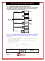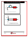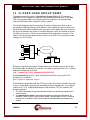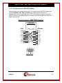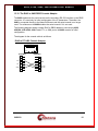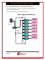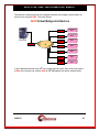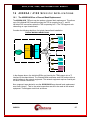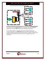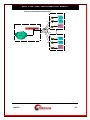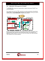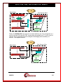
1
99448800 –– 44118800 -- 44228800 –– 44228844 –– 44000000X XA A MULTIPLE PROTOCOL INTEGRATED ACCESS DEVICE USER’S MANUAL 4180 Release: 14.x 4280 Release: 3.x 4000XA Release: 14.x 4284 Release: 7.x 9480 Release: 7.x 102 SW Orange Blossom Lake City, Florida 32025-1613 phone: 386-754-5700 email: [email protected] http://www.trdcusa.com Manufacture & Distribution: http://www.datatekcorp.com 9480, 4180, 4280, 4284 4000XA User Manual 1 IMPORTANT SAFETY INSTRUCTIONS....................................................................................... 6 2 INTRODUCTION ............................................................................................................................... 8 2.1 2.2 2.3 2.4 2.5 2.6 2.7 2.8 2.9 2.10 3 PHYSICAL DESCRIPTION ............................................................................................................ 12 3.1 3.2 3.3 3.4 3.5 3.6 3.7 3.8 4 CLOSED USER GROUPS............................................................................................................ 9 HUNT GROUPS ........................................................................................................................... 9 DNS FEATURES.......................................................................................................................... 9 TACACS+ RADIUS LOGIN SUPPORT......................................................................................... 9 ALARM RELAY UNIT ALARM GRID INTERFACE ............................................................. 10 PEER TO PEER SECURE SOCKET CRYPTOGRAPHY ........................................................................ 10 X.25 MEDIATION FEATURES ........................................................................................................ 10 TIME SLOT ROUTER (TSR) FEATURES ......................................................................................... 10 E2A HEAD OF BRIDGE FEATURES ................................................................................................ 10 ESAM EXTENSION BOARD SUPPORT ........................................................................................... 11 POWER INTERFACES.............................................................................................................. 12 ALARM RELAY UNIT INTERFACE ....................................................................................... 13 CONSOLE INTERFACE ........................................................................................................... 13 4180 RS-232/V.11/RS-530SERIAL INTERFACE ..................................................................... 13 10/100 BASE-T INTERFACE .................................................................................................... 14 TSR ............................................................................................................................................. 14 USER PORTS ............................................................................................................................. 14 LEDS ........................................................................................................................................... 15 INSTALLATION............................................................................................................................... 16 4.1 REQUIRED EQUIPMENT......................................................................................................... 16 4.2 INSTALLATION FOR AC-ONLY OPERATION ..................................................................... 16 4.3 INSTALLATION FOR DC OPERATION ................................................................................. 17 4.4 CABLING THE 4000XA, 4180, 4280, 4284 CONSOLE ........................................................... 18 4.5 9480 INITIAL CONFIGURATION CONSOLE CABLING ...................................................... 20 4.6 DATA TRANSPORT CABLING – SAM16 REPLACEMENT ................................................. 21 4.6.1 Asynchronous User Port Connections .................................................................................... 21 4.6.2 Synchronous User Port Connections ...................................................................................... 21 4.7 DATA TRANSPORT CABLING ............................................................................................... 22 4.7.1 User Ports............................................................................................................................... 22 4.8 ORDERING INFORMATION ............................................................................................................ 22 4.9 THE 9116 INTELLIGENT PATCH PANEL .............................................................................. 23 4.10 THE 9008 RS-530/V.35/RS-422/V.11 ADAPTER ......................................................................... 26 4.11 9001 DISCRETE TELEMETRY ADAPTER ........................................................................................ 27 4.12 FIELD UPGRADE AND SOFTWARE REGISTRATION ....................................................................... 31 5 CONFIGURATION .......................................................................................................................... 34 5.1 OVERVIEW ............................................................................................................................... 34 5.2 BASE CONFIGURATION ......................................................................................................... 34 5.2.1 Console Security ..................................................................................................................... 34 5.3 USER PORT CONFIGURATION .............................................................................................. 34 5.3.1 IP Originating Ports ............................................................................................................... 35 5.3.2 IP Receive Ports ..................................................................................................................... 35 5.3.3 IP Closed User Groups........................................................................................................... 36 5.4 4000XA, 4180 IP-GATE PORT CONFIGURATION ................................................................ 37 6 COMMAND REFERENCE.............................................................................................................. 38 04/09/09 2 9480, 4180, 4280, 4284 4000XA User Manual 6.1 BASE CONFIGURATION COMMANDS................................................................................. 38 6.1.1 LOGIN .................................................................................................................................... 38 6.1.2 LOGOUT ................................................................................................................................ 38 6.1.3 CHANGE PASSWORD ........................................................................................................... 38 6.1.4 LOCAL.................................................................................................................................... 39 6.1.5 GATEWAY .............................................................................................................................. 39 6.1.6 DOMAIN NAME SERVER...................................................................................................... 39 6.1.7 TACACS+ RADIUS Servers ................................................................................................... 40 6.1.8 HELP ...................................................................................................................................... 40 6.1.9 VERSION ................................................................................................................................ 40 6.1.10 REBOOT ............................................................................................................................ 41 6.1.11 REMOVE MODULE .......................................................................................................... 41 6.1.12 RESTORE MODULE ......................................................................................................... 41 6.1.13 CLEAR ............................................................................................................................... 41 6.1.14 DISPLAY MODULE MEASUREMENTS ........................................................................... 42 6.1.15 DISPLAY LOG ................................................................................................................... 42 6.1.16 VERIFY MODULE ............................................................................................................. 42 6.1.17 HOST NAME ADMINISTRATION ..................................................................................... 42 6.1.18 VERIFY HOST ................................................................................................................... 42 6.1.19 SNMP ................................................................................................................................. 42 6.1.20 INSTALL ( Software Registration ) .................................................................................... 44 6.1.21 RSTPASS ( Resetting the Password ) ................................................................................. 44 6.1.22 CONSOLE TIMEOUT ........................................................................................................ 45 6.1.23 Label................................................................................................................................... 45 6.1.24 PING .................................................................................................................................. 45 6.1.25 TraceRoute ......................................................................................................................... 46 6.1.26 TSR CONFIGURATION .................................................................................................... 46 6.1.27 DATA-BASE RESET ........................................................................................................... 48 6.1.28 DISCONNECT CONSOLE ................................................................................................. 48 6.1.29 ADMINISTER SECURITY BANNER .................................................................................. 49 6.1.30 CLOSED USER GROUP (CUG) ADMINISTRATION....................................................... 49 6.1.31 VERIFY CUG ..................................................................................................................... 49 6.1.32 ASSIGNING A CUG TO THE CONSOLE.......................................................................... 49 6.1.33 Administrative Logins & Command Security ..................................................................... 50 6.1.34 eSAM Board Configuration ................................................................................................ 51 6.2 USER PORT COMMANDS ....................................................................................................... 52 6.2.1 PORT ...................................................................................................................................... 52 6.2.2 REMOVE PORT ..................................................................................................................... 62 6.2.3 RESTORE PORT .................................................................................................................... 62 6.2.4 DISPLAY PORT MEASUREMENTS ...................................................................................... 62 6.2.5 VERIFY PORT ........................................................................................................................ 62 6.2.6 DISPLAY PORT STATUS ....................................................................................................... 62 6.2.7 DISPLAY CONNECTIONS ..................................................................................................... 63 6.2.8 DIAGNOSE USER PORT ....................................................................................................... 63 6.2.9 DISCONNECT USER PORT .................................................................................................. 63 6.2.10 X.25 Protocol Analyzer Snooper ........................................................................................ 63 6.2.11 E2A Head of Bridge Analyzer Snooper .............................................................................. 64 6.2.12 E2A Head of Bridge Mapping Functions ........................................................................... 64 6.2.13 Configuring User Prompt................................................................................................... 65 6.3 IP-GATE PORT COMMANDS .................................................................................................. 65 6.3.1 IPGATE ROUTE..................................................................................................................... 65 6.3.2 IPGATE PATH ....................................................................................................................... 66 6.3.3 IP-GATE PORT ...................................................................................................................... 66 04/09/09 3 9480, 4180, 4280, 4284 4000XA User Manual 6.3.4 6.3.5 6.3.6 6.3.7 6.3.8 6.3.9 6.3.10 7 SNMP .................................................................................................................................................. 69 7.1 7.2 7.3 8 SNMP VERSION 1 COMMANDS.................................................................................................... 69 XXXX SNMP MIB VARIABLE DATABASE.................................................................................... 69 SUPPORTED TRAPS....................................................................................................................... 71 ALARMS ............................................................................................................................................ 72 8.1 8.2 8.3 9 REMOVE IP-GATE ................................................................................................................ 67 RESTORE IP-GATE ............................................................................................................... 67 VERIFY IP-GATE ................................................................................................................... 67 DISPLAY IP-GATE STATUS .................................................................................................. 67 DMEAS IP-GATE ................................................................................................................... 67 DISCONNECT IP-GATE ........................................................................................................ 67 DISPLAY IP-GATE ARP CACHE ...................................................................................... 67 MAJOR ALARMS .......................................................................................................................... 72 MINOR ALARMS .......................................................................................................................... 72 INFO ALARMS .............................................................................................................................. 72 MODULE MEASUREMENTS ........................................................................................................ 73 10 USER PORT MEASUREMENTS.................................................................................................... 74 11 IP-GATE PORT MEASUREMENTS.............................................................................................. 74 12 CLOSED USER GROUP DEMO..................................................................................................... 75 13 CABLING........................................................................................................................................... 76 13.1 13.2 13.3 13.4 13.5 13.6 13.7 13.8 13.9 13.10 13.11 13.12 13.13 13.14 13.15 13.16 13.17 13.18 13.19 13.20 13.21 XXXX PORTS AND THE UDS 202T MODEM .................................................................................. XXXX PORTS AND AT&T/PARADYNE 2024 MODEM.................................................................... XXXX PORTS AND GENERAL DATACOMM 201-7 MODEMS .......................................................... CABLING TO A MODEM SET ......................................................................................................... CABLING DIRECTLY TO THE NETWORK ELEMENT ....................................................................... CABLING TO A WESTRONIC WS2000 E2A REMOTE .................................................................... 4000XA, 4180, 4280 - CABLING TO AN AT&T SAC E2A REMOTE ............................................. 9480, 4284 - CABLING TO AN AT&T SAC E2A REMOTE ............................................................ CABLING TO AN AT&T GENERAL TELEMETRY PROCESSOR (GTP) ............................................. CABLING TO AN AT&T TELEMETRY NETWORK CONTROLLER (TNC) .................................... CABLING TO A DPS NETWORK TELEMETRY PROCESSOR (NTP) ............................................. THE SYNCHRONOUS DTE ADAPTER ........................................................................................ THE SYNCHRONOUS DCE ADAPTER........................................................................................ THE ASYNCHRONOUS DTE ADAPTER ..................................................................................... THE ASYNCHRONOUS DB9 DTE ADAPTER ............................................................................. THE ASYNCHRONOUS DCE ADAPTER ..................................................................................... THE DB9 CONSOLE ADAPTER ................................................................................................. THE RJ45 TO RJ45 CROSSOVER CONSOLE CABLE ................................................................... THE RJ45 TO 9480 DB25 CONSOLE ADAPTER ........................................................................ THE RJ45 TO RJ45 FULL CROSSOVER CABLE ......................................................................... THE RJ45 LAN CROSSOVER CABLE ........................................................................................ 76 76 77 77 77 78 79 80 81 82 83 84 85 86 87 88 89 90 91 92 93 14 SYNCHRONOUS PROTOCOLS WITH RECOVERED CLOCKS ............................................ 94 15 AN E2A HEAD OF BRIDGE EXAMPLE ...................................................................................... 95 04/09/09 4 9480, 4180, 4280, 4284 4000XA User Manual 16 4000XA / 4180 SPECIFIC APPLICATIONS .................................................................................. 97 16.1 16.2 THE 4000XA/4180 AS A CHANNEL BANK REPLACEMENT ........................................................... 97 4000XA/4180 TSR SUPPORT FOR IP-FANOUT .........................................................................100 17 SPECIFICATIONS ..........................................................................................................................102 17.1 CONSOLE PORT ......................................................................................................................102 17.2 4000XA / 4180 RS-232/V.35 DB25 SERIAL PORT.................................................................102 17.2.1 RS-232-C ...........................................................................................................................102 17.2.2 V.35 ...................................................................................................................................102 17.3 4000XA, 4180, 4280, 4284, 9480 ...............................................................................................102 17.4 10/100 LAN PORT ....................................................................................................................102 17.5 PHYSICAL DIMENSIONS .......................................................................................................103 17.6 ENVIRONMENTAL OPERATING RANGE ...........................................................................103 17.7 POWER REQUIREMENTS ......................................................................................................103 17.8 REGULATORY INFORMATION ............................................................................................104 17.8.1 xxxx Stand-Alone ...............................................................................................................104 17.8.2 FCC Part 68 Information ..................................................................................................104 17.8.3 Industry Canada CS03 Certification Information .............................................................105 17.8.4 NEBS COMPLIANCE .......................................................................................................105 18 HARDWARE WARRANTY ...........................................................................................................107 19 END-USER LICENSE AGREEMENT FOR SOFTWARE .........................................................107 19.1 19.2 19.3 19.4 19.5 19.6 19.7 19.8 SOFTWARE LICENSE ...................................................................................................................107 INTELLECTUAL PROPERTY RIGHTS .............................................................................................107 SOFTWARE SUPPORT ...................................................................................................................107 EXPORT RESTRICTIONS ...............................................................................................................107 LIMITED WARRANTY ..................................................................................................................107 NO OTHER WARRANTIES ............................................................................................................108 LIMITATION OF LIABILITY ..........................................................................................................108 SPECIAL PROVISIONS ..................................................................................................................108 20 SALES & DISTRIBUTION .............................................................................................................109 21 AUTHOR ...........................................................................................................................................109 04/09/09 5 9480, 4180, 4280, 4284 4000XA User Manual 1 I M P O R TA N T S A F E T Y I N S T R U C T I O N S ! The exclamation point within an equilateral triangle is intended to alert the user to the presence of important operating and maintenance (servicing) instructions in the literature accompanying the product. When installing, operating, or maintaining this equipment, basic safety precautions should always be followed to reduce the risk of fire, electric shock, and injury to persons, including the following: Read and understand all instructions. Follow all warnings and instructions marked on this product. For information on proper mounting instructions, consult the User’s Manual provided with this product. The telecommunications interface should not leave the building premises unless connected to telecommunication devices providing primary and secondary protection. This product should only be operated from the type of power source indicated in the User’s Manual. This unit must be powered from either –48 V DC, or AC voltage sources. Additionally, the 4000XA, 4180 and 4280 may be powered by a 24VDC source. The 4280 may also be powered via the Ethernet Interface. The –48 V DC input terminals are only provided for installations in Restricted Access Areas locations. Do not use this product near water, for example, in a wet basement. Never touch non-insulated wiring or terminals carrying direct current or leave this wiring exposed. Protect and tape wiring and terminals to avoid risk of fire, electric shock, and injury to service personnel. To reduce the risk of electrical shock, do not disassemble this product. Only trained personnel should perform servicing. Opening or removing covers and/or circuit boards may expose you to dangerous voltages or other risks. Incorrect re-assembly can cause electric shock when the unit is subsequently used. For a unit intended to be powered from –48 V DC voltage sources, read and understand the following: This equipment must be provided with a readily accessible disconnect device as part of the building installation. Ensure that there is no exposed wire when the input power cables are connected to the unit. Installation must include an independent frame ground drop to building ground. Refer to User’s Manual. This symbol is marked on the 4180, 4280 and 4284, adjacent to the ground (earth) area for the connection of the ground (earth) conductor. 04/09/09 6 9480, 4180, 4280, 4284 4000XA User Manual This Equipment is to be Installed Only in Restricted Access Areas on Business and Customer Premises Applications in Accordance with Articles 110-16, 110-17, and 110-18 of the National Electrical Code, ANSI/NFPA No. 70. Other Installations Exempt from the Enforcement of the National Electrical Code May Be Engineered According to the Accepted Practices of the Local Telecommunications Utility. For a unit equipped with an AC Wall Plug-In Unit, read and understand the following: For the 4280, use only the PHIHONG, Model PSA-30U-240 power supply adapter. For the 4000XA or 4180, use only the K’TRON, Model KA-52A Wall Plug-In power supply adapter. For the 9480 or 4284, use only the Astrodyne Part # SPU15A-111 48 volt power supply adapter. Unplug this product from the wall outlet before cleaning. Do not use liquid cleaners or aerosol cleaners. Use a damp cloth for cleaning. Do not staple or otherwise attach the power supply cord to the building surfaces. Do not overload wall outlets and extension cords as this can result in the risk of fire or electric shock. The socket outlet shall be installed near the equipment and shall be readily accessible. The Wall Plug-In unit may be equipped with a three-wire grounding type plug, a plug having a third (grounding) pin. This plug is intended to fit only into a grounding type power outlet. Do not defeat the safety purpose of the grounding type plug. Do not allow anything to rest on the power cord. Do not locate this product where persons walking on it may abuse the cord. Unplug this product from the wall outlet and refer servicing to qualified service personnel under the following conditions: a) When the powers supply cord or plug is damaged or frayed. b) If liquid has been spilled into the product. c) If the product has been exposed to rain or water. d) If the product does not operate normally by following the operating instructions. Adjust only those controls that are covered by the operating instructions because improper adjustment of other controls may result in damage and will often require extensive work by qualified technician to restore the product to normal operation. e) If the product has been dropped or the cabinet has been damaged. f) If the product exhibits a distinct change in performance. SAVE THESE INSTRUCTIONS 04/09/09 7 9480, 4180, 4280, 4284 4000XA User Manual 2 INTRODUCTION The 9480, 4180, 4000XA, 4284, and 4280 are Multiple Protocol Inter-Networking devices. In this document, the term xxxx or unit will mean any of these devices. The 4000XA, 4180, 4280, 9480, and 4284 include optional enhanced vertical service feature packages such as X.25 mediation in various capacities. The 9480 and 4284 also support the E2A Bridge Network emulation feature package. Other feature packages are similarly available. The 4000XA and 4180 support a Time Slot Router (TSR) port. The TSR port allows transport of proprietary protocols on DS0s, or aggregated on a DS1. The T1, E1, and J1 formats are all supported. The 4000XA and 4180 support an IP-GATE LAN interface for providing a VPN service with disjoint addressing. The IP-GATE port provides access to a secure and reliable virtual private network separate from the other functions of the 4180. It provides an interLAN networking connection over an IP network that would otherwise not be secure enough to carry this traffic. This provides complete connectivity with any remote IPGATE via an IP network. Many hardware variations support an IP-GATE. For example, a 2020 1+ SAM + IP-GATE combination provides such a connection. Similarly, IP-GATE ports on two 4180s can communicate with each other over an IP network. An IP-GATE resident on a BNS network may be used as a peer by interfacing through the Universal Mediation Interface (UMI) Module. If it is desirable to provide access to a LAN in a central site from a large number of remote sites, the IP-GATE port on the main-site 4180 can be configured to interconnect with the IP-FANOUT application on a 6xxx Embedded Network Processor located anywhere on the IP network. Please see the Solution Document “Secure and Reliable Intranet Access For Remote Sites” for a more detailed discussion of this use of the IP-FANOUT application on the 6xxx. The 9480 is a single port device, the 4284 has 4 serial ports, the 4000XA and 4180 each have 16 serial ports, and the 4280 has 32 serial ports. All of the serial ports are synchronous, or asynchronous that support speeds up to 115.2kbps. Popular protocols such as Asynchronous, various Bi-Synchronous variants, HDLC, SDLC, X.25, and E2A are all supported interchangeably on a per-port basis. In addition, vertical services typically found on Embedded Network processors have been incorporated into the devices as feature packages. For example, this allows for the direct mediation of X.25 to individual circuits over TCP connections when the X.25 vertical service is selected on a port. The 9480 and 4284 devices also allow the emulation of the E2A Bridge network when the E2AHOB vertical service is selected on a port. 1 The 2020 is a stand-alone unit, which interfaces an existing SAM to an IP network instead of a BNS network. This gives IP network access to devices connected to the SAM ports without any re-cabling. 04/09/09 8 9480, 4180, 4280, 4284 4000XA User Manual The xxxx is an internet protocol (IP) access device. That is, it mediates any of the supported protocols and the IP protocol suite. This includes IP, TCP, Telnet, RTP, ARP, SNMP, etc. The 4000XA, 4180, 4280, 4284, and 9480 hardware is each individually unique, but comparable to the 4000. The 4000XA hardware is identical to the 4000 as it is an in situ software conversion. The notable differences are power options, number of ports, serial port type, and the 10BaseT vs 10/100 LAN connection for IP connectivity. The xxxx series provide expanded or additional feature packages. The 4280 allows 48VDC, nominal 24VDC (18-72V), or AC via a power cube. In addition, the 4280 may be supplied by Power over Ethernet (POE) on the LAN port thereby eliminating any power connection. The 9480, and 4284 hardware are similar to the 4280 except the power options are 48VDC nominal, Power over Ethernet (POE), or AC via the power cube. Notably missing is the nominal 24VDC (18-72V) power option present on the 4280. The 4180 allows 48VDC (18-72V), 5VDC, or AC via a power cube. The 4180 does not support Power over Ethernet(POE). 2.1 CLOSED USER GROUPS This is an important feature for protecting sensitive endpoints in a corporate-wide network without the burden of special “security servers”. The xxxx provides security with an implementation of Closed User Group (CUG) membership and calling security. This is a capability similar to that provided in X.25 networks but now available for an IP infrastructure. A closed user group restricts access between xxxx ports and domains or individual endpoints in the IP network. No external security systems of any kind are required. A CUG application example is presented at the end of this manual. 2.2 HUNT GROUPS A Hunt Group is a set of ports arranged to receive calls to a common address. The xxxx provides this capability for user ports configured to receive calls from the IP network. 2.3 DNS FEATURES The xxxx can maintain a set of mnemonic host names, analogous to the /etc/hosts file on both UNIX and Microsoft Windows platforms. This allows the xxxx to perform a translation between a user-provided name and its associated IP address and TCP port number. (The use of a mnemonic name is optional, as the xxxx will always accept an IP address in its numeric form.) The xxxx also allows for the definition of an external Domain Name Server (DNS) to be used for mnemonic addresses not defined in the host table. Multiple Domain Name Servers are supported. They are searched in priority order. 2.4 TACACS+ RADIUS LOGIN Support The xxxx supports up to two TACACS+ RADIUS servers for login authentication. These are a primary, and a secondary, although each is individually enabled. The TACACS+ support is for either encrypted, or clear authorization. Encryption keys may contain spaces. 04/09/09 9 9480, 4180, 4280, 4284 4000XA User Manual 2.5 ALARM RELAY UNIT ALARM GRID INTERFACE The 4000XA, 4180, and the 4280, each provide a standard wiring for activation of the alarm grid should the hardware encounter a fault condition. The fault conditions include a total loss of power to the device. The alarm grid interface may be wired for normally open or normally closed connections. 2.6 Peer To Peer Secure Socket Cryptography The xxxx will support peer to peer communications using secure cryptography. This is important for Internet Protocol (IP) networks where the contents of the peer session is to be protected from network sniffer devices. The cryptography feature is selectable on a per port basis, and both session endpoints should be set identically. The cryptography key selection is dynamic, and automatic. 2.7 X.25 Mediation Features The 4280 has thirty two instances of the X25PAD mediation application. The 4180 has sixteen instances of the X25PAD mediation application. The 4000XA has sixteen instances of the X25PAD mediation application. The 4284 has four instances of the X25PAD mediation application. The 9480 has one instance of the X25PAD mediation application. Use of the X25PAD application is exclusive of any other vertical service application (e.g. E2AHOB) or feature package. Each of the serial ports on these devices may be connected to a (B)X.25 interface. The X25PAD mediation application allows a telnet client to interface on a per VC basis. In addition, X.25 pass-through for VC aggregation is fully supported. Each VC may be individually configured as a PAD or a PASS-THROUGH interface. A specialty interface for the MacStar operations system is supported. The Record Boundary Preservation protocol is supported. SVC hunt groups across X.25 lines are specifically supported allowing fault tolerant X.25 links to be established. The (B)X.25 session layer is specifically supported via an API. 2.8 Time Slot Router (TSR) Features The 4180 provides one RJ48C for a TSR interface. The RJ48C supports T1, E1, or J1 software configurable. Each time slot may be uniquely routed on the IP WAN. Individual CODECs may be installed for load optimization. HDLC time slots may be terminated for use by 6xxx applications, or for routing to serial ports. 2.9 E2A Head of Bridge Features The 4280 does not support the E2AHOB mediation application at this time. The 4180 does not support the E2AHOB mediation application at this time. The 4000XA does not support the E2AHOB mediation application at this time. The 4284 has four instances of the E2AHOB mediation application. 04/09/09 10 9480, 4180, 4280, 4284 4000XA User Manual The 9480 has one instance of the E2AHOB mediation application. Use of the E2AHOB application is exclusive to any other vertical service application (e.g. X25PAD) or feature package on a particular port. Each of the serial ports on these devices may be configured, on a per port basis, to be connected to an E2A head of bridge. The head of bridge may be an E2A port on an OS such as NMA, an intermediary device such as a TNC, or merely a modem in an existing bridge chain. The E2AHOB mediation application allows a switched virtual bridge network to be created using standard E2A ports on the same or other devices. A virtual distribution bridge of up to 31:1 may be created in this manner. The E2AHOB provides a display of the dynamic address map, and a full decoding protocol snooper. The E2AHOB has provision for display of the dynamic E2A address map, and an E2A decoding protocol snooper. 2.10 eSAM Extension Board Support The devices may be used as an extension board to a eSAM. The eSAM is a network extensible variant of the SAM series for Datakit and BNS networks. This feature allows the device to be used as a single port, four port, sixteen port, or 32 port board to extend a eSAM. The device does not need to be co-located with the eSAM as it uses the IP infrastructure for communications. See the eSAM product addendum for more information. 04/09/09 11 9480, 4180, 4280, 4284 4000XA User Manual 3 PHYSICAL DESCRIPTION 3.1 POWER INTERFACES 48VDC Power Rack-mounted or operating stand-alone, the 4180, 4280, 4000XA, and 4284 accept DC power input directly from a 48V DC power source which connects to the three position (return, -48, and ground) terminal block labeled 48V DC on the faceplate. The terminal block connectors accommodate 10 awg (American Wire Gauge) to 14 awg wire. A strain-relief clamp is available separately for DC wire stabilization. The actual voltage range of the 4180, 4280, and 4000XA is 18 through 72 volts inclusive. The 9480 accepts 48VDC power on a circular connector. The 9480 voltage tolerance is +/- 10%. The 4284 voltage tolerance is +/- 10%. 24VDC Power Rack-mounted or operating stand-alone, the 4280 accept DC power input directly from a 24 VDC (nominal) via a circular connector. The circular connector is labeled 24VDC on the 4280 faceplate. The actual voltage range is 18 through 72 volts inclusive. AC Power For this application, a separate AC power supply is available which plugs into a standard 115/240V AC outlet. The power supply has a six-foot cable that terminates with a barrel connector. The barrel connector plugs into the circular connector labeled 24VDC on the 4280 faceplate. The barrel connector plugs into the circular connector labeled 5VDC on 04/09/09 12 9480, 4180, 4280, 4284 4000XA User Manual the 4000XA and 4180 faceplate. The AC power cube plugs into the circular connector labeled 48VDC on the 4284, and the 9480. Power Over Ethernet The 4280, 4284, and 9480 will accept power on the LAN connection using the POE specification. When used, no additional power is required by the device. Redundant Power The 4280, 4284, and 9480 may be connected to power on each of their supported interfaces. For example, the “Power over Ethernet” may be used at the same time as 48V power on the circular connector. The power supplies are isolated from each other and completely redundant. If one should fail, the other is used without interruption. Note that the 4280 may be triple redundant with Power over Ethernet, 48V on its 3-prong interface, and 18-72v on its circular connector. 3.2 ALARM RELAY UNIT INTERFACE The Alarm Relay Unit connector is a three position (Failed Open, Closed, Failed Closed) terminal block labeled ALARM on the 4000XA, 4180 or 4280 faceplate. The terminal block connectors accommodate 10-awg to 14-awg wire. 3.3 CONSOLE INTERFACE The console interface is used for initial configuration, and for StarKeeper® II NMS monitoring on an on-going basis.2 This interface requires a standard RJ45-terminated twisted-pair data cable on the 4000XA, 4180, 4280, and 4284. It connects as a data terminating equipment (DTE) to an asynchronous device and uses RS-232C signaling. It is configured as 9600 bps, 8 bits, no parity and one stop bit. On the 9480, the serial console interface is available on the secondary port pins of the DB25 connector (Pins 14 & 16). Once initially configured, all operations may use the telnet console. 3.4 4180 RS-232/V.11/RS-530SERIAL INTERFACE The DB25 RS-530 male connector on the 4000XA and 4180 provides support for software-selectable device interfaces (V.35 and RS232-C) at data rates up to 2Mbps. The DB25 RS-530 interface is a DTE only. The male connector electrically presents a data terminal equipment (DTE) interface and supports RS-232C directly. For V.35, a standard RS-530 DB25 Female to V.35 Winchester-34 Male adapter is available. 2 The xxxx also provides access to the console function through a TCP telnet connection via a reserved telnet server port (TCP port 1023). This service is available only when the unit is in service, and may be protected by Closed User Group membership. 04/09/09 13 9480, 4180, 4280, 4284 4000XA User Manual 3.5 10/100 BASE-T INTERFACE The LAN connection on the 4280, 4284, and 9480 is a 10/100 BaseT interface on the front of the unit and is labeled “LAN”. The interface requires a standard RJ45 terminated Category 5 twisted-pair data cable. It connects to a 10/100 Hub, EtherSwitch, or router on a local LAN segment providing access to a wide-area IP based network. This port supports TCP/IP peer-level protocols (e.g. TELNET, TCP, IP, ARP, SNMP, etc.). The LAN interface will automatically negotiate the speed with the network interface PHY. The 4000XA and 4180 provides two LAN connections with similar interface capable of 10BaseT operation. These are labeled LAN and GATE for their distinct functions. 3.6 TSR The 4000XA and 4180 DSU interface uses an industry-standard RJ48C connector. The option of using the interface for T1 (1.544 MHz) or E1 (2.048 MHz) is software selectable. The TSR is used to transport individual time slots with on T1/E1 interfaces. 3.7 USER PORTS The user serial ports support both asynchronous and synchronous protocols in either DCE or DTE modes. Configuration is selectable on a per port basis. Baud rates up to 115.2kbps are supported. Synchronous ports support NRZ & NRZI. The NRZI format supports recovered clocks for isochronous (i.e. 2 wire) operation. The V.35 and RS-530 interfaces require a 9008 adapter, or a 9116 intelligent patch panel. The RS-232 physical interface may be done via the 9116 intelligent patch panel, or directly from the user port interface. When using a RJ45 interface, an industry standard RJ45 to DB25 adapter is utilized. The 9008 adapter and the 9116 intelligent patch panel each provides a DB25 interface. See the cabling information contained in this user manual. 04/09/09 14 9480, 4180, 4280, 4284 4000XA User Manual 3.8 LEDs The faceplate contains light emitting diodes (LEDs) used to report 4000XA or 180 activity and status. LED Function PWR ALARM LNK (each PHY) COL (each PHY) RX (each PHY) TX (each PHY) TSR LED Color Green Red Green Red Yellow Yellow Red LED Description Unit Power Indicator Reset Indicator & General Failure Indicator LAN Link Indicator LAN Collision Indicator LAN Receive Packet Indicator LAN Transmit Packet Indicator LOS Indicator The faceplate contains light emitting diodes (LEDs) used to report 4280 activity and status. LED Function PWR ALARM LNK/ACT DPX/COL LED Color Green Red Green Red LED Description Unit Power Indicator Reset Indicator & General Failure Indicator Link & Activity (Blink) Indicator Duplex & Collision (Blink) Indicator The 4284, and the 9480 use the following light emitting diodes: LED Function PWR LNK/ACT 04/09/09 LED Color Green Green LED Description Unit Power Indicator Link & Activity (Blink) Indicator 15 9480, 4180, 4280, 4284 4000XA User Manual 4 I N S TA L L AT I O N This chapter contains the steps needed to install and cable the 4xxx. The 9480 is directly attached to the network element via a DB25 interface. A #2 Phillips and mediumsized flathead screwdrivers are required. 4.1 REQUIRED EQUIPMENT To install either a rack-mounted or stand-alone device, the following items are needed: • One 4000XA, 4180, 4280, 4284, or 9480 unit • For AC operation, AC power supply • For DC operation, a strain-relief clamp for wire stabilization Cables – refer to CABLING sections 4.4 through 4.7 below to determine specific requirements for this installation. Note: Shielded cables must be used in order to maintain compliance with EMC requirements. For rack-mount installations only: • An EIA standard 19-inch or 23-inch equipment rack with internal, vertical mounting rails. Hole spacing on the vertical-mounting rail must be 1.25 inches. Use the dimension specifications to calculate how high the rack needs to be to support the required number of units. • A pair of mounting brackets for each 4000XA, 4180, or 4280. The 4284 uses the IPDSU mounting bracket. • The Environmental Operating Range of 5 to 40 degrees C (41 to 124 degrees F) is necessary to maintain compliance with UL. 4.2 INSTALLATION FOR AC-ONLY OPERATION 1) Stand-Alone: Attach the provided feet to the bottom of the unit Rack-Mount: Attach the mounting brackets to each side of the unit. 2) Stand-Alone: Place the unit in the desired location, such as a shelf in a data equipment rack. Rack-Mount: Fasten the unit to a 19-inch equipment rack (using appropriate rack screws) or use extension ears for a 23-inch rack. 3) Attach data transport cables – refer to section 4.5 4) Attach console cable by plugging one end of an RJ45-terminated twisted-pair data cable into the console interface and the other into the port of the asynchronous device that will be used to configure or manage the unit. 5) Plug the power supply into a standard 115V AC outlet and the barrel connector on the power supply cable into the appropriate circular connector on the faceplate. Labeled 24VDC on the 4280, 5VDC on the 4000XA, and 4180, and 48VDC on the 4284 and 9480. 04/09/09 16 9480, 4180, 4280, 4284 4000XA User Manual 4.3 INSTALLATION FOR DC OPERATION 1. 4000XA and 4180 Power Strapping. The 4000XA and 4180 is factory configured for 115V AC usage. 48V DC operation requires a different jumper setting on the 4180 system board. Refer to the diagram below and perform the following steps: 4180 top down view JP2 48V 5V FRONT Disconnect any power connectors from the unit. Remove the unit cover, exposing the top portion of the system board. Locate the jumper connector (JP2) and move the jumper to the 48v setting. Replace the unit cover. 2. Stand-Alone: Attach the provided feet to the bottom of the unit Rack-Mount: Attach the mounting brackets to each side of the unit. 3. Stand-Alone: Fasten the strain relief to the side of the unit. Rack-Mount: Fasten the strain relief to the unit rack-mount bracket. 4. Stand-Alone: Place the unit in the desired location, such as a shelf in a data equipment rack. Rack-Mount: Fasten the unit to a 19-inch equipment rack (using appropriate rack screws) or use extension ears for a 23-inch rack. 5. Attach data transport cables – refer to section 4.5 6. Attach console cable by plugging one end of an RJ45-terminated twisted-pair data cable into the unit console interface and the other into the port of the asynchronous device that will be used to configure or manage the unit. 7. Run 48V DC (return, -48, and ground) wires from a central source through the strain relief clamp for DC wire stabilization. On the faceplate, attach the return, -48, and ground wires to the return, -48, and ground connections, respectively, on the terminal block labeled 48V DC. 8. Rack-Mount: The Environmental Operating Range of 5 to 40 degrees C (41 to 124 degrees F) is necessary to maintain compliance with UL. 04/09/09 17 9480, 4180, 4280, 4284 4000XA User Manual 4.4 CABLING THE 4000XA, 4180, 4280, 4284 CONSOLE This section describes the options for cabling the 4xxx console port, to allow the 4xxx to be managed by a terminal, PC, dial-up modem, or asynchronous network connection. The following diagram shows the connection options: AH Male modular cable modular cable 4x8x RJ45 AH Male AH Male Ortronics patch panel AH Male PC or Dumb Terminal 9pin Console Adapter PC or Dumb Terminal modular cable (SPECIAL WIRING) modular cable Modem straped for constant DTR 258 adapter or mod tap patch panel modular cable (SPECIAL WIRING) modular cable SAM 16 To Node To remote modem B25 Cable to ty12, msm sam64/504 To ty12, msm sam64/504 Important! A modular cable with “SPECIAL WIRING” can be ordered using the table below or built using the wiring diagrams provided in this manual. • • • Configure SAM, TY12 and MSM console connections as 9600 bps with 8 bits and no parity, and use a DCE type cable. Configure SAM and MSM console connections as type “host” and as a “pap” (permanently active port). Configure TY12 console connections as type “console”. Additional instructions for configuration of SAM, TY12 or MSM asynchronous ports may be found in the appropriate BNS module reference guide. The following cables and adapters are available for console connections: Cable or Adapter 04/09/09 Order Information (Lucent) Order Information (Reseller) 18 9480, 4180, 4280, 4284 4000XA User Manual modular cable (10’) modular cable (special wiring) AH male connector Ortronics Patch Panel 258 Adapter 04/09/09 407981646 408198133 ED5P055-31 G139 406485755 ED5P055-31 G(155) modular cable (length) modular cable (special wiring) AH male connector Ortronics Patch Panel 258 Adapter 19 9480, 4180, 4280, 4284 4000XA User Manual 4.5 9480 INITIAL CONFIGURATION CONSOLE CABLING The serial console is needed to initially configure the 9480’s IP parameters. These are limited to the IP address, the Gateway address, and IP Network Submask. Otherwise, the serial console is normally disconnected during normal operation, and telnet console access via TCP port 1023 is used. The 9480 does not preclude a serial console connection during normal operation. Should such be desired, a “Y” cable is needed on the DB25 implementing the console connection. The 9480 serial console configuration wiring options are as follows: Modular Cable (Special Wiring) 9480 AH Male PC or Dumb Terminal RJ45 Serial Console Adapter Modular Cable PC or 9-pin Console Dumb Adapter Terminal 9480 Serial Console Options The 9480 has no RJ45 jack, like other TeleComp R&D Migration Products, for connection of a serial console. Before connection to the Network Element, a DB25 to RJ45 adapter with special wiring must be attached to the 9480. The serial console is connected via this adapter and cabling as shown in the figure above. Specific wiring information is found in the cabling section of this document. The serial console is configured as 9600 baud, 8 bits, and no parity. 04/09/09 20 9480, 4180, 4280, 4284 4000XA User Manual 4.6 DATA TRANSPORT CABLING – SAM16 REPLACEMENT This section describes the procedures for cabling a unit being used to replace a SAM16. Existing SAM16 cabling will be reused. The unit will interface to an IP infrastructure and not a BNS trunk. BNS connectivity shall be via a Universal Mediation Interface (UMI) module. Please consult the UMI documentation for more information. For a completely new installation, this section should still be read first. Differences will be noted in section 4.6. 4.6.1 Asynchronous User Port Connections The 4000XA, 4180, 4280, and 4284 each have RS-232C (RJ45) connectors presented as data terminal equipment (DTE) interfaces, in place of the DB25 connectors on the SAM16. These RJ45 connectors use the same pinouts that each port on a 4000, SAM64, or SAM504 uses. The following steps are needed for each asynchronous user port to complete the SAM16 replacement: • DTE DEVICE 1. Remove the existing DB25 cable from the SAM16 port. 2. Attach a D8AG-F (25-pin-F to mod socket, null modem wiring) adapter to the DB25 cable. 3. Connect a D8W (mod plug to mod plug, straight through) cable from the D8AG-F to the corresponding xxxx RS-232C user port. • DCE DEVICE 1. Remove the existing DB25 cable from the SAM16 port. 2. Remove the existing DCE to DCE adapter. 3. Attach a D8AH-F (25-pin-F to mod socket, straight through) adapter to the DB25 cable. 4. Connect a D8W (mod plug to mod plug, straight through) cable from the D8AH-F to the corresponding xxxx RS-232C user port. 4.6.2 Synchronous User Port Connections The following steps are needed for each synchronous user port to complete the SAM16 replacement: • DTE DEVICE 1. Remove the existing DB25 cable from the SAM16 port. 2. Attach a SYNC DCE-F (25-pin-F to mod socket) adapter to the DB25 cable. 3. Connect a D8W (mod plug to mod plug, straight through) cable from the SYNC DCE-F adapter to the corresponding xxxx RS-232C user port. • DCE DEVICE 1. Remove the existing DB25 cable from the SAM16 port. 2. Remove the existing DCE to DCE adapter. 3. Attach a SYNC DTE-F (25-pin-F to mod socket) adapter to the DB25 cable. 4. Connect a D8W (mod plug to mod plug, straight through) cable from the SYNC DTE-F adapter to the corresponding xxxx RS-232C user port. 04/09/09 21 9480, 4180, 4280, 4284 4000XA User Manual 4.7 DATA TRANSPORT CABLING . 4.7.1 User Ports Although the 4000XA, 4180, 4280, and 4284 are each configured to work like a SAM16, the pin outs on the RJ45 connectors used for the RS-232 user ports are identical to the pin outs for the SAM64 and SAM504 user ports. Thus, all adapters and cables used with these SAM types will apply to the unit. Refer to the Cabling section of Data Networking Products Synchronous/Asynchronous Multiplexer Reference. In most cases, a standard RJ45-terminated Category 5 twisted-pair data cable can be used, with the appropriate adapter (depending on the gender) on the connector on the endpoint device. 4.8 Ordering Information Cable or Adapter Description V.35(M) to DB25(F) D8AG-F 34-pin-M 25-pin-F 25-pin-F mod socket, null modem wiring D8AH-F 25-pin-F mod socket Mod plug Mod plug, straight through, 3ft. 25-pin-F mod socket 25-pin-F mod socket D8W SYNC DCE-F SYNC DTE-F 04/09/09 Order Information (Lucent) 408418911 ED5P055-31 G138 ED5P055-31 G147 408421803 ED5P055-31 G150 ED5P055-31 G151 Order Information (Reseller) V.35(M) to DB25(F) D8AG-F D8AH-F D8W SYNC DCE-F SYNC DTE-F 22 9480, 4180, 4280, 4284 4000XA User Manual 4.9 THE 9116 INTELLIGENT PATCH PANEL The 9116 Intelligent Patch Panel (IPP) is used to provide software selectable physical interfaces to the 4180 or 4280 user ports. The 9116 supports RS-232, V.35, V.11, RS530, RS-530A, X.21, RS-422, RS-449, and V.36 interfaces. The 9116 can operate as a DTE or a DCE on a per port basis. The following is a diagram of the 9116 IPP: 9116 IPP Front View 9116 IPP Rear View Please note that the 9116 does not have switches of any kind. All configuration information is dynamically set by the 4000XA, 4180 or 4280. The DB25 interfaces are on the rear side of the panel, and the RJ45 interfaces and LED indicators are on the front side. The 9116 IPP is connected to the 4000XA, 4180 or 4280 on a port by port basis using a short RJ45 to RJ45 straight cable. There is no requirement to connect all of the 4000XA, 4180 or 4280 ports to the 9116 IPP. Each port will operate independently. 04/09/09 23 9480, 4180, 4280, 4284 4000XA User Manual The 9116 requires a +5V power input, and will also cascade the power to the next device. The +5V to the 9116 may be parasite power from the 4280 +5V output connector. In the alternative, a separate AC adapter may be used for the 9116. The 9116 DB25 ports are configured with the physical interface selected on the 4000XA, 4180 or 4280 user console. The ports may operate in DTE or DCE modes. The DB25 is a female and is a native physical DCE. For physical DTE operation, a wiring adapter (or cable) is required. The logical DTE operation is incorporated automatically by the 9116 IPP. This physical DTE-DTE wiring is as follows: Signal GND SGND TxD RxD RTS CTS DCD DTR SCTE 04/09/09 DB25 Male (J1) 9116 End. 1 7 2 14 3 16 4 19 5 13 8 10 20 23 24 11 DB25 Male (J2) DCE Device End. 1 7 3 16 2 14 5 13 4 19 20 23 8 10 17 (also Connect to J2 – 24) 9 (also Connect to J2-11) 24 9480, 4180, 4280, 4284 4000XA User Manual Each 9116 port has 15 LED indicators. These are described as follows: Lamp RxD TxD DCD CTS DSR RTS DTR CLK SCTE SYNC DCE V.11/V.35 RS-530(A) Status Configure Function DB25 Receive Data indication. DB25 Transmit Data indication. DB25 Data Carrier Detect indication. DB25 Clear to Send indication. DB25 Data Set Ready indication. DB25 Request to Send indication. DB25 Data Terminal Ready indication. DB25 RxC and TxC indication. DB25 External Timing indication. Port is operating in synchronous mode. Asynchronous mode when not illuminated. Port is operating in logical DCE mode. Logical DTE mode selected when not illuminated. Port is operating in V.11 or V.35 mode. RS-232 mode when both V.11/V.35 and RS-530(A) lamps are extinguished. Port is operating in RS-530 or RS-530(A) modes. RS-232 mode when both V.11/V.35 and RS-530(A) lamps are extinguished. 9116 IPP port reporting status information to the xxxx. The xxxx is actively configuring the 9116 port. The 9116 is also available in a single port version called the 9116-S. This is shown below. The single port version of 9116 has all of the features and automatic configuration but no LED displays. The convenient size requires no rack space and converts the RJ45 to DB25 directly. If a Winchester-34 cable is required, a Black Box FA058 or FA059 DB25 to Winchester-34 adapter is attached to the 9116. 04/09/09 25 9480, 4180, 4280, 4284 4000XA User Manual 4.10 The 9008 RS-530/V.35/RS-422/V.11 Adapter The 9008 series of adapters are used to provide balanced physical interfaces to the 4000XA, 4180, 4280, and 4284 user ports. The 9008 supports V.35, V.11, RS-422, and RS-530 interfaces. The 9008 is available is DCE and DTE variants. It uses an industry standard RJ45 to connect to the 4180, 4280 and 4284. It provides an industry standard RS-530 DB25 interface for the balanced physical interface. For legacy interfaces that require a Winchester 34 connection, the Black Box FA059 (DTE), and FA058 (DCE) wiring adapters may be used. The picture below depicts a 9008-DTE with the Black Box FA059 Winchester 34 pin adapter. 04/09/09 26 9480, 4180, 4280, 4284 4000XA User Manual 4.11 9001 Discrete Telemetry Adapter The 9001 adapter provides an inexpensive telemetry interface for 16 discrete elements. It is used in conjunction with an application such as VTELRMT implementing a virtual E2A remote; or with the ONSITE application for general purpose telemetry. The applications are instances on a 6xxx embedded network processor. The 9001 appears as follows: The 9001 provides the following features: Each SCAN point is optically isolated from the xxxx to which it is attached. Each SCAN point is optically isolated from the 9001. Each SCAN point is optically isolated from all other SCAN points. The 9001 does not require external power for operation. The 9001 minimizes and simplifies telemetry wiring. The 9001 does not require any rack space and each supports 16 isolated scan points. The 9001 reports the rack ambient temperature. The 9001 may be attached to the 9480 or any 4xxx serial port. The 9001 is the lowest cost telemetry solution. The diagrams below are per the “Network Terminal Equipment Operations Interface Specifications (TR 43904). 04/09/09 27 9480, 4180, 4280, 4284 4000XA User Manual Ground Footprint User Supplied Voltage 9001 4xxx Contact or Transistor Closure User Supplied Voltage Return SS Type 1 - Isolated Loop Closure Inside Building User Supplied Voltage 9001 4xxx Contact or Transistor Closure Ground or User Supplied Voltage Return SS Type 2 - Isolated Closure to Ground 04/09/09 28 9480, 4180, 4280, 4284 4000XA User Manual User Supplied Voltage Coil, Lamp, Etc. Load 9001 4xxx Contact or Transistor Closure Ground or User Supplied Voltage Return SS Type 3 - Isolated Closure to Ground with Load Ground Contact or Transistor Closure Coil, Lamp, Etc. Load 9001 4xxx Battery PS Type 1 - Inputs Requiring Battery and Ground Isolation (Note: TR43804 External Resistor is not required) 04/09/09 29 9480, 4180, 4280, 4284 4000XA User Manual Ground Footprint Battery 9001 4xxx Contact or Transistor Closure Outside Building Ground PS Type 2 - Isolated Loop Closure Outside Building (Note: TR43804 External Resistor not required.) As can be seen from the diagrams above, the 9001 in conjunction with the VTELRMT application can replace an E2A Telemetry device for discrete scan points. 04/09/09 30 9480, 4180, 4280, 4284 4000XA User Manual 4.12 Field Upgrade and Software Registration The unit, when initially delivered, will need one or more software keys to activate the software. Software keys are also required when an optional individual feature packages are added to the device. Finally, when the unit is upgraded with revised software, one or more software keys are required to register the installed software and any feature packages registered for the device. When performing an upgrade, the revised software is initially downloaded by upgrade3 into a staging area and is not active. The software then is activated by a reboot. The new software will execute normally prior to registration. However, no backup, reloads, or upgrades can be performed. Module level parameters, such as the device IP address, may be changed and activated. If a user port is taken out of service, the port cannot be restored. The procedure for performing a software registration has been mechanized. Manual procedures are error prone and not recommended. They are no longer covered in this user manual. The mechanized Software Upgrade Registration procedure allows simplified administration of one or more devices. When a quantity of devices are upgraded, manual software registration of each device has the potential of becoming increasingly tedious. The mechanized software upgrade registration process was designed to alleviate the problems associated with multiple device upgrades. It is also preferred for single device upgrades as it eliminates any potential for error. The new software is downloaded to the unit via the upgrade command. This may be performed for one or more devices. The “-r” option to the dtupgrade command will restart the device on the new software after the download completes successfully. It is highly recommended. In the alternative, the device may be downloaded without a restart and restarted at a later time during a scheduled maintenance window. Restarting the device on the new software prior to registration is required. After the restart, the devices will continue to operate normally on the new software without registration. Some operations interface functions are inhibited pending software registration. Below is an example of a typical upgrade invocation. Note the use of the “-r” option as it is recommended. upgrade –v –d –r –i –m9480 10.0.1.80 dt_94xx.4.2 Mechanized registration is performed in three steps. Each of which does not require user intervention. The steps are as follows: 3 Utilities may be renamed to any other name. The names shown are those on the distribution. 04/09/09 31 9480, 4180, 4280, 4284 4000XA User Manual 1. The getinfo utility is invoked on a file containing a list of devices to be administered. This file is called the master device list file and is typically named “device.master”. The master device list file may have any name and it is provided as an argument to the getinfo utility. The master device list may also contain devices that do not require registration. The getinfo utility makes inquiry of each device in the master device list and creates a device information file named “dt_device.info” in the current directory. 2. The “dt_device.info” file is then sent via email to [email protected] for registration processing. 3. A file name “dt_device.register” file is returned via email to be used as input in the next step. A file named “dt_device.msgs” is a text file that may be displayed or printed showing the results of the registration function. 4. The setreg utility is invoked and uses the “dt_device.register” file provided as an argument. If no argument is provided, the file is assumed to be in the current directory. The setreg utility contacts each device that requires registration and have been assigned keys. One or more keys are installed during the dialogue. 5. The “dt_device.info” file and the “dt_device.register” file are deleted as they are transient and have no further value. Neither can be reused for the purpose of registration. However, the dt_device.info file may be used for inventory reports.. The source for the registration procedure is the inventory master device list file that is created, and maintained, by the administrator using their favorite text editor. The master device list file contains one IP address per line, with an optional TCP port, and an optional password override, to access the device. The IP address is the console connection address, and not necessarily the actual device IP address. Registration via the serial console is explicitly supported. Comments are allowed between addresses, and after addresses. A password override is only required if the default password of “initial” has been changed. The master device file line format is as follows: <IP ADDRESS> [<TCP PORT>] [-P<Password>] # Comment An example “device.master” file follows: # This is a Sample master device list file “device.master”. # Note that there is one device ( Connect IP Address ) per line. # TCP Port Override is allowed. Registration may use the serial console. # Password Override is allowed. # It is OK to have devices that do not need registration listed for inventory. # Comments in this file are preceded with a pound symbol. # Blank Lines are treated as comments. # Basic Line Format is as follows: 10.0.1.80 # Device at Location ‘A’ 192.168.7.82 # Device at Location ‘B’ 04/09/09 32 9480, 4180, 4280, 4284 4000XA User Manual 192.168.7.155 50001 # Example of TCP port Override. 192.168.7.156 50001 –pcustom1 # Example of Password Override. Once the “device.master” file is prepared, it is used as an input to the getinfo utility. getinfo dt_device.master This getinfo utility will collect information on each device in the master file. The getinfo utility will also make a determination if a registration is actually required. Consequently, the getinfo utility is also useful in performing inventory functions outside of the device registration. The output of the getinfo utility is a file named “dt_device.info” that is always created in the current directory. The file “dt_device.info” is attached to an email and sent to the address [email protected]. The registration procedure is performed and a file named “dt_device.register” is attached to return email to the original sender. A messages file named “dt_device.msgs” is also attached and may be printed as a report of the key generation function. After receiving the “dt_device.register” file, the setreg utility is invoked with the relative path of the “dt_device.register” file as it’s sole argument. The setreg utility will only contact the devices that actually need registration, and for which one or more keys were successfully generated. All of the appropriate keys, including a device key and multiple per port feature package keys, are installed by the setreg utility. The device is not restarted and this operation may occur during normal transport operation. A report utility devrep is available. The devrep utility uses the “dt_device.info” file to display the inventory information. The usage is as follows: devrep [-v] dt_device.info If the file is not specified, the devrep utility attempts to use the “dt_device.info” file resident in the current directory. 04/09/09 33 9480, 4180, 4280, 4284 4000XA User Manual 5 C O N F I G U R AT I O N 5.1 OVERVIEW The overall configuration process can be divided into three phases: Base Configuration – setting up the unit for IP network connectivity, console security, and other general maintenance operations such as displaying measurements and exception logs User Port Configuration – setting up the unit to enable connections to be established between specific user ports and endpoints on IP networks, performing measurements and diagnostics on user ports IP-GATE port configuration, if required on the 4000XA, or 4180. TSR port and timeslot configuration, if required on the 4000XA, or 4180. Actual command sequences will be presented throughout this section to illustrate the configuration process. Section 6 of this document should be used as the reference for console commands. 5.2 BASE CONFIGURATION For IP networking, it is necessary to configure the IP address and subnet mask, the IP address of the gateway router, the IP address of an SNMP manager (optional), and the IP address of a domain name server (optional). To illustrate an IP networking configuration, the following is a command sequence for a basic installation. <4280> <4280> <4280> <4280> 5.2.1 login passwd=initial ↵ local ipaddr=135.17.59.165 submask=255.255.255.0 ↵ gateway ipaddr=135.17.59.1 ↵ restore mod ↵ Console Security Console-security parameters, i.e., an administrative login password and the (optional) timeout for automatic console logoff, will also be set up at this time. 5.3 USER PORT CONFIGURATION 04/09/09 34 9480, 4180, 4280, 4284 4000XA User Manual 5.3.1 IP Originating Ports User ports designated as originating, using the port command, are used to establish connections to endpoints on the IP network. A predefined destination (PDD), in the form of a destination IP address and TCP port number, is required for a user port configured for a synchronous protocol. A PDD is optional for an asynchronous port. For asynchronous ports, operation from the perspective of a user is determined by whether or not a PDD has been specified. An originating user port which has a PDD associated with it will have that connection automatically established when the user device goes “off hook”, i.e., signals DTR, or when the user sends the attention sequence. If no PDD has been specified, the calling user is instead greeted with a xxxx Destination> prompt where xxxx is the actual product number. The user would then enter the destination IP address plus TCP port number desired. If no TCP port number is entered, the telnet default (23) is used. The user also has the option to enter a mnemonic host name previously administered into the unit’s host table. The session is terminated when the calling user types the attention sequence. If a Domain Name Server has been defined on the unit, the calling user may also enter a fully qualified destination name (e.g. “server.ab.company.com”) to be resolved. It is also possible to override the TCP port while still resolving the IP address. For example, the dial string “server.ab.company.com 50030” selects TCP port 50030 and then asks DNS to resolve “server.ab.company.com” to an IP address. An originating port optioned for one of the supported synchronous protocols should be configured as a permanently active port (PAP), and also have a PDD specified. This will cause the desired connection to be established as soon as the port is restored to service. The following example command sequence would set up an originating user port that would allow the connected endpoint to “dial” other endpoints in the IP network. It will be configured for 9600 baud, 8 bits, no parity, and no PDD defined. It will default to asynchronous operation. Assume the unit is already configured for IP networking, and in service. <4280> port 2 type=orig baud=9600 dbits=8 parity=none ↵ <4280> restore port 2 ↵ 5.3.2 IP Receive Ports A unit is accessible from anywhere in the IP network via a single IP address. That is the address administered using the local command, as previously shown. At this address, each user port configured as receive, using the port command, “listens” on a configured TCP port for the arrival of an incoming call from somewhere in the IP network. Once a call is established, the telnet over TCP protocol is used for transport. A hunt group may be established, by assigning the same TCP port number to more than one receive user port. Ports included in a given hunt group do not need to be contiguous. 04/09/09 35 9480, 4180, 4280, 4284 4000XA User Manual The following example command sequence would establish a hunt group of receive user ports to support a modem pool reachable from anywhere in the IP network. Ports #1, #9, and #13 are to be part of the hunt group, at TCP port 51000. They will be configured for 9600 baud, 8 bits, no parity, and permanently active. Assume the xxxx itself is already configured for IP networking, and in service. <4280> port 1 type=rcv hport=51000 baud=9600 dbits=8 parity=none pap=on ↵ <4280> port 9 type=rcv hport=51000 baud=9600 dbits=8 parity=none pap=on ↵ <4280> port 13 type=rcv hport=51000 baud=9600 dbits=8 parity=none pap=on ↵ <4280> restore port 1 ↵ <4280> restore port 9 ↵ <4280> restore port 13 ↵ 5.3.3 IP Closed User Groups The unit has its own implementation of closed user groups (CUGs) to control access between its user ports and endpoints on the IP network. The cug command is used to create a closed user group, as a single IP address or range of addresses in a sub net. The port command allows up to 16 CUGs to be associated with a port. Calls in either direction are restricted as follows: • A call to an IP address from an orig-type user port will be blocked unless the destination IP address belongs to at least one of the CUGs associated with that user port. • A call to the TCP port number corresponding to a receive-type user port will be blocked unless the calling IP address belongs to at least one of the CUGs associated with the port. Please see the CUG example at the end of this manual for a CUG application example using the xxxx. 04/09/09 36 9480, 4180, 4280, 4284 4000XA User Manual 5.4 4000XA, 4180 IP-GATE PORT CONFIGURATION A sequence of three commands: ipgate route ipgate path ipgate port configures the IP-GATE port on the 4000XA, or 4180. The ipgate route command configures the screening and routing table for the IP-GATE port, which specifies a set of destination IP address ranges for which packets originating on the LAN segment connected to the IP-GATE port should be forwarded or dropped. The ipgate path command defines the physical path to be used for forwarding packets. A path can be thought of as a “private tunnel” through an IP infrastructure, public or private. It is set up to either originate or receive a TCP/IP connection, specified by the combination of an IP address and TCP port number. A path over TCP/IP is also secure, because only one TCP connection is accepted at the specified IP-GATE destination (unlike standard host TCP implementations), and this will be set up automatically by the firmware. The ipgate port command specifies the interface configuration of the IP-GATE port on the virtual private network formed by the interconnected LANs. It is a basic address and mask so that the interface may be pinged. 04/09/09 37 9480, 4180, 4280, 4284 4000XA User Manual 6 COMMAND REFERENCE These commands are used to configure the operation of the 4000XA, 4180, 4280, 4284, and 9480 devices. Not all commands are visible all the time. Should the unit be logged out, only the login command is visible. The reboot command places the unit in the logged-out mode. Commands may be entered in upper or lower case. Parameters of the form name=<value> may use upper or lower case for name. Case is preserved for values. Backspace erases one character. Changes are cumulative. After running a configuration command (especially those with many parameters) it is always a good idea to run the corresponding verify command, to check for any defaulted values which may need to be overridden. 6.1 BASE CONFIGURATION COMMANDS 6.1.1 LOGIN Syntax #1: login passwd=<password> (default password is: initial) Syntax #2: login This command is a security command required for accessing the bulk of the command set. It is only available when the user is logged off. The command has two forms, and three modes of operation. The first syntax example provides legacy compatibility for operations systems that use that form. The password must contain between one and seven alphanumeric characters. The typed password is case sensitive. In the second example, the password is not provided on the command line. The login command will then prompt for a password. A password given at the prompt will not be echoed. There is a timeout of approximately 30 seconds on the password prompt. If one or more TACACS+ RADIUS Servers are defined, the second form is used to log into the device. When used, a connection is made to the first available server. Prompts for “Username” and “Password” are requested. These Usernames and Passwords are administered on the TACACS+ RADIUS server; and not on the device. 6.1.2 LOGOUT Syntax: logout This command returns the unit to its logged-out mode, thus preventing unauthorized access. 6.1.3 CHANGE PASSWORD Syntax: chgpass old=<password> new=<password> confirm=<password> 04/09/09 38 9480, 4180, 4280, 4284 4000XA User Manual This command allows the user to change a previously configured password. The old password is the one currently in effect. The new and confirm passwords should be identical. The password must contain between one and seven alphanumeric characters. The typed password is case sensitive. All arguments are required to complete the command. 6.1.4 LOCAL Syntax: local [ipaddr=<IP address>] [submask=<submask>] [tcpunreach=< ICMP | RESET >] [phy=<AUTO | 10HDX | 100HDX>] This command sets up IP networking for this unit. The mac (address) parameter is a fixed attribute for each unit that is set at the factory. The ipaddr parameter is the IP address of this unit. The submask parameter is the subnet mask of the LAN segment on which this unit is located, with a default value of 255.255.255.0. The operation of the unit, when it is called to an invalid TCP port, is specified with the tcpreach=<ICMP | RESET>] parameter. When set to ICMP, the caller is sent an “ICMP Port Unreachable” message. When set to RESET, the TCP connection is sent a TCP reset to the initiator. The [phy=<AUTO|10HDX|100HDX>] option allows the selection of the LAN PHY on the 4284 and 9480. The default operation is the AUTO value that specifies automatic negotiation with the etherswitch. When AUTO is selected, the PHY will negotiate to 10Mbps or 100Mbps as allowed by the etherswitch. At the current time, the operation is always HDX. Fixed rates may be selected. The value of 10HDX specifies a fixed rate of 10Mbps for the PHY connection to the etherswitch. The value of 100HDX specifies a fixed rate of 100Mbpx for the PHY connection to the etherswitch. 6.1.5 GATEWAY Syntax: gateway ipaddr=<IP address> This command identifies the IP address of the local gateway router, if any. The gateway router is the first hop packets travel through to reach a remote destination address residing on a different LAN segment. 6.1.6 DOMAIN NAME SERVER Syntax: dns [ ipaddr1=<IP Address> ] [ ipaddr2=<IP Address> ] [ ipaddr3=<IP Address> ] [ name1=<Domain Name> ] [ name2=<Domain Name> ] [ name3=<Domain Name> ] The dns command is only visible when the unit is logged in. Each ipaddrX field is the IP address of a Domain Name Server to be used for mnemonic addresses not defined in the host table. When all are set to 0.0.0.0, the DNS functions 04/09/09 39 9480, 4180, 4280, 4284 4000XA User Manual are disabled. The DNS addresses are used in order. If only one address is to be defined, it is required to be ipaddr1. The name1, name2, and name3 parameters are domain names. These domain names are appended to a dial string which is not fully specified for DNS purposes. For example, a name “bender.ho.lucent.com” is fully specified, so nothing is appended. A name such as “bender” would need to have a domain appended before the DNS server could resolve it. The unit will append the specified domain names in the order of name1 through name3, and send the resulting strings to the DNS server in succession until the latter is able to perform a resolution. 6.1.7 TACACS+ RADIUS Servers Syntax: tac < PRI | SEC > [ ipaddr=<IP Address> ] [ port=<TCP Port> ] [ key=”Encryption Key” | NONE ] [ ENABLE ] [ DISABLE ] The tacplus command is only visible when the unit is logged in. The tac command allows the configuration of up to two TACACS+ RADIUS servers for the device. the servers are used as a primary server and a secondary server, although they may be individually disabled. The < PRI | SEC > syntax specifies which server is to be configured. A server may not be configured while enabled The [ ipaddr=<IP Address> ] specifies the IP address of the configured server. The [ port=<TCP Port> ] specifies the TCP port to use when communicating with the server. The TACACS+ service defaults to TCP port 49, but any port may be specified. The [ key=”Encryption Key” | NONE ] specifies an encryption key to use. The Encryption key must be enclosed in double quotes, and the double quotes are not part of the key. If no encryption is desired, the value of NONE is used to designate unencrypted service. The ENABLE command allows this server to be used for service, and prevents further configuration. The DISABLE command prevents this server from being used for service, and subsequently allows configuration. 6.1.8 HELP Syntax: help This command produces a display of the entire command set and syntax available for the mode (logged out or logged in) the unit is currently in. 6.1.9 VERSION Syntax: ver 04/09/09 40 9480, 4180, 4280, 4284 4000XA User Manual This command displays the current software and database revisions of the unit and is only visible when the user is logged in. The ver command also displays the authorization level of the user currently logged into the administrative console. The command has no arguments. If new software has been downloaded and no reboot has been performed; the new software version is also displayed. 6.1.10 REBOOT Syntax: reboot [newip=<New IP Address>] [newmask=<New Network Mask>] [newgate=<New Gateway Address>] This command resets the unit, which allows configured physical attributes to take effect. The command is only visible if the user is logged in. The command has optional arguments to allow the remote alteration of the network configuration. If any network configuration change is required, the user is prompted for the password as a verification check before the reboot is actually executed. After the reboot, the console interface returns to the logged-out mode. The reboot command will always prompt for a password for validation purposes even if the administrator is logged at the appropriate level or higher. 6.1.11 REMOVE MODULE Syntax: remove mod This command is only visible when the unit is logged in. The command has no additional arguments. The command takes the unit out of service. This command must be performed before any unit-level configuration changes can occur. The remove mod command will always prompt for a password for validation purposes even if the administrator is logged at the appropriate level or higher. 6.1.12 RESTORE MODULE Syntax: restore mod This command is only visible when the unit is logged in. The command has no additional arguments. It returns the unit to service. If any physical attribute was changed on the unit, including the MAC address, the unit will be automatically rebooted by this command. 6.1.13 CLEAR Syntax: clear < meas > This command is only visible when the unit is logged in. When the argument value is meas, the current measurements are all set to zero. No other options are allowed at this time. 04/09/09 41 9480, 4180, 4280, 4284 4000XA User Manual 6.1.14 DISPLAY MODULE MEASUREMENTS Syntax: dm mod This command is only visible when the user is logged in. It displays the current, unit-level measurements in a formatted report on the console (see for an itemization of the unitlevel measurements at the end of this manual). Port information is not displayed on the unit-level report. 6.1.15 DISPLAY LOG Syntax: dlog This command is available only on the 4000XA, and 4180, and displays the IP-GATE exception logs. The IP-GATE exception log provides details about the last 32 errors recorded. Not all errors generate exception entries. These logs may be cleared using the clear logs command. 6.1.16 VERIFY MODULE Syntax: vfy mod This command is only visible when the unit is logged in. The command displays the unitlevel configuration in a formatted report on the console. 6.1.17 HOST NAME ADMINISTRATION Syntax: host <host #>[name=<host name>][ipaddr=<IP address>] [port=<TCP port>][del] The units all support mnemonic destination name translation for non-PDD originating user ports. These mnemonic names are translated into an IP address and TCP port during call setup. The host command is used to configure the translation table The name field is a mnemonic for a destination up to nine characters in length. The ipaddr (of the host) and TCP port (on the host) parameters specify the translation to be performed during call setup. If the parameter del is used, the entry is deleted. 6.1.18 VERIFY HOST Syntax: vfy host This command is only visible when the unit is logged in. It displays host-address configuration in a formatted report on the console. 6.1.19 SNMP Syntax: snmp [ ipaddr= < trap mgr addr > ] [ port= < trap mgr port > ] [ CUG=<<+|-> CUG Number> ] 04/09/09 42 9480, 4180, 4280, 4284 4000XA User Manual [ PUBLIC=< YES | NO > ] [ COMM=”Double Quoted String” | NONE ] [ SYSCONTACT=”Double Quoted String” | NONE ] [ SYSNAME=”Double Quoted String” | NONE ] [ SYSLOC=”Double Quoted String” | NONE ] This command is used to configure the IP address of the SNMP trap manager. Since traps are unsolicited alarms, an agent can take the initiative to inform the manager of the occurrence of a predefined condition. Typical conditions include the cold-start or warmstart of equipment and a link-down or link-up condition. A single and multiple SNMP managers can access the unit. However, only one SNMP manager can be defined as the trap manager. As a result of this command, all traps will be directed to the chosen trap manager. The ipaddr field defines the IP address of the SNMP manager to which the traps are to be sent. The port field indicates the UDP port on that SNMP manager and defaults to the standard value of 162. Any combination of closed user group membership may be assigned to the SNMP interface using the parameter of cug=[+|-]<CUG Number>. The closed user group membership is displayed on the “verify module” output. Packets which have failed the SNMP Closed User Group Test are discarded. An alarm is not presented, but the failure is counted. The number may be displayed with the “dmeas mod” command. The unit allows setting of an SNMP community in addition to the public community. The public community is recognized when the [ PUBLIC=YES ] option is selected. Recognition of the public community is the default operation. When [ PUBLIC=NO ] is selected, the public community is not recognized. The xxxx allows setting of an SNMP community in addition to the public community. When configured, the xxxx will respond to SNMP manager requests in that community. The xxxx will always respond to a request in the public community. The settable SNMP community is configured with the [ COMM=”Double Quoted String” | NONE ] option. The community may be in any case. The double quote encapsulation is not part of the community string. The settable community may be cleared by setting it to the keyword NONE. The MIB-II variables sysName, sysContact, and sysLocation may be initialized from the xxxx non-volatile database using the SNMP command. These variables are volatile in that they may be over-written by an SNMP manager. However, any change made by the SNMP manager will not impact the xxxx non-volatile database. Setting the value to NONE will clear the entries in the xxxx non-volatile database. Each field may be of 31 characters or less. The double quote encapsulation is not part of the respective variable. Any of the variables may be cleared by setting it to the keyword NONE. 04/09/09 43 9480, 4180, 4280, 4284 4000XA User Manual 6.1.20 INSTALL ( Software Registration ) Syntax: install [ key=<software key> ] [ fpkey=<software key>] The xxxx has a unique device software key, and multiple per port feature package keys. This section is included in the user manual for completeness. Under normal circumstances, only the mechanized utilities utilize this command. It may be executed manually under an emergency situation. Depending on the device, the keys may or may not be installed by the factory. The per port feature package keys my be added at any time, and do not affect the operation of the unit. The registration procedure does not require a restart to take effect on a device running the registered software. When executed without arguments, the install command will display the significant information needed to manufacture the device software key. The device IP address may also be required. No additional information is needed to create the feature package keys. The key=<software key> argument allows the entry of an eight-character alphanumeric software registration that is unique to this xxxx device. If an invalid key is entered, a MINOR alarm is generated to that effect. The passwords are not altered. The rstpass command has been created to reset the passwords should that become necessary. The fpkey=<software key> argument allows the entry of an eight-character alphanumeric software registration that is unique to a port, and software feature package, on this xxxx device for the current software build. The specific feature package referenced by the software key becomes immediately available on the port without subsequent download. The <software key> has effect on only one port. Other ports on the device are not affected. If the same software feature package is needed on multiple ports, then multiple feature package keys are applied. The install command is always available. 6.1.21 RSTPASS ( Resetting the Password ) Syntax: rstpass [ key=<Password Key> ] The rstpass command is a command whose function is to reset the password(s) of the device to factory default values. This function was formerly performed as part of the software registration. Breaking it out into a separate command allows the software to be registered without password updates to take place. When invoked without arguments, the rstpass command will display the relevant information needed to generate the <Password Key>. This information is relayed to the technical support staff. The generated key is then used with the key=<Password Key> argument. The rstpass command should not be run between the time the key data is generated and the <Password Key> is utilized. Similarly, if the device is restarted, the resultant <Password Key> will not perform its intended function. 04/09/09 44 9480, 4180, 4280, 4284 4000XA User Manual 6.1.22 CONSOLE TIMEOUT Syntax: timeout [ off | < number of minutes > ] The xxxx console uses a three-wire interface (RD, TD, GND), and the lead state of other signals is not relevant. This would imply that the only way to change the state of the console is to explicitly log in or log out or via a reboot or reset, which forces the console to be logged out. For users who wish the console to automatically log off after a period of inactivity, there is a console timer. The console timer defaults to the disabled condition, and may be activated by the timeout command. This command is only visible when the console is logged in. The <number of minutes> value must be between 1 and 255, inclusive. When the xxxx determines a period of inactivity of the specified time, it automatically forces the console to log off. An INFO-level alarm is issued at that time. 6.1.23 Label Syntax: label [ “Double Quoted String” | none ] The label command is used to give the command console a unique prompt. The command is visible only when logged into the xxxx administrative console. If the label command is invoked without arguments, the current configuration of the label is displayed. If the argument to the label command is the word ‘none’, any current label is set to a null value. If the argument to the label command is a double quoted string, the contents of the string becomes the application console prompt label. A console label may be up to 31 characters in length. 6.1.24 PING ping <IP address> [ Interval Seconds ] The ping command is only visible when the unit is logged in. The command has a single required argument, the IP address that is to be pinged. The ping command formats an ICMP echo request packet which is then sent to the IP Address specified. The device with that address will issue an ICMP echo reply to the request. This is required of all IP implementations by RFC 791. If a reply is received, an informational alarm is issued on the UMI console. If no reply is received, there is a timeout message that will appear for that ICMP echo request. The ping command issues a single ICMP echo request packet and awaits a response. The response is printed, and another ICMP echo request is issued. The operation continues until the user presses any character. The [ Interval Seconds ] argument specifies the amount of time to wait in seconds between the individual ICMP echo requests. 04/09/09 45 9480, 4180, 4280, 4284 4000XA User Manual It should be noted that some host Internet Protocol implementations issue duplicate responses to a single ICMP request. The ping command will suppress duplicate replies. 6.1.25 TraceRoute trte <IP address> The trte command is only visible when the unit is logged in. The command has a single required argument, the IP address that is to be pinged. The trte command formats an ICMP echo request packet that is then sent to the IP Address specified. The valid packet “time to live” is set to an initial value of “1”. If the IP address is on the local subnet, the ICMP echo will respond immediately. If the IP address is on a different subnet, the gateway router will decrement the “time to live” upon routing the packet. When the “time to live” reaches zero, the gateway sends an ICMP “time exceeded” message to the xxxx. The xxxx then displays the gateway device, and increments the “time to live” on the next ICMP echo request packet. This continues until the IP address is reached. The result is a display of all the intermediary gateway devices used to reach the IP address from the xxxx. If no answer is received, each “time to live” value is tried 3 times before an increment. The timeout is 5 seconds for each attempt. The maximum number of “time to live” is set to 30 in this build of the xxxx. Since a traceroute command can be unusually long in duration, any character sent to the console will interrupt the operation of the traceroute command. 6.1.26 TSR CONFIGURATION Syntax: TSR [frmr = < e1 | t1 > ] [prof = < t1 waveform > ] [timing = < int | net > ] chan=<Channel #> [addslot = <all | slot_no> ] [delslot = <all | slot_no> ] [tsrate=<64|56|48|40|32|24|16|8>] [type=< ORIG | RCV >] [codec=< HDLC | TRANS >] [dest=<IP Address> dport=<TCP Port>] [hport=<Hunt Group TCP Port Number>] [crc=< 16 | 32 >] This command configures the RJ48C Time Slot Router interface on the 4000XA and 4180. The TSR supports channels that contain one or more timeslots. There are 24 channels available for a T1 connection to the TSR, and 32 channels available for an E1 connection to the TSR. Each channel is independent, and may be used for HDLC based data or for bit-independent data such as voice. When HDLC based data is specified, the HDLC protocol is terminated on the 4000XA/4180 and only user traffic traverses the IP network. The network protocol for HDLC TSR channels is TCP, and is compatible with 6xxx based applications. When transparent based data is specified, the 4000XA/4180 04/09/09 46 9480, 4180, 4280, 4284 4000XA User Manual uses the IP “real time protocol (RTP)” for delivery in an expedient manner without underrun or over-run. The TSR may be configured in one or multiple instances of the same command (changes are cumulative). The frmr parameter indicates what basic framing is being used. A value of T1 is used for domestic 1.544 MHz interfaces with 193 Bit Superframes. A value of E1 is used for European interfaces at 2.048 MHz with 256 Bit Superframes. The prof parameter indicates the Transmission Waveform to be used with T1 transport. There is only one E1 transport profile, which is automatically set. The following table indicates the available waveforms for T1. Option 0DB 7DB 15DB 22DB S0 S110 S220 S330 S440 S550 T0 TS0 TS110 TS220 TS330 TS440 TS550 Description T1 Long Haul w/ 0 DB Attenuation. T1 Long Haul w/ 7.5 DB Attenuation. T1 Long Haul w/ 15 DB Attenuation. T1 Long Haul w/ 22 DB Attenuation. T1 Short Haul @ 0-110 Feet. T1 Short Haul @ 110-220 Feet. T1 Short Haul @ 220-330 Feet. T1 Short Haul @ 330-440 Feet. T1 Short Haul @ 440-550 Feet. T1 Short Haul @ 550-660 Feet. TR62411 T1 Long Haul w/ 0 DB Attenuation. TR62411 T1 Short Haul @ 0-110 Feet. TR62411 T1 Short Haul @ 110-220 Feet. TR62411 T1 Short Haul @ 220-330 Feet. TR62411 T1 Short Haul @ 330-440 Feet. TR62411 T1 Short Haul @ 440-550 Feet. TR62411 T1 Short Haul @ 550-660 Feet. The TR62411 nomenclature indicates compliance to the AT&T TR62411 ACUNET T1.5 pulse template. It is to be used for situations requiring such compliance. The timing parameter indicates the timing signal to be used for transmission. A value of INT (internal) indicates that the 4000XA/4180 should generate the transmit clock internally from its precision oscillator. A value of NET (network) indicates that the 4000XA/4180 should recover the transmit clock from the receive data stream and use it for transmission. It should be noted that there may only be one master clock in the DSU interface between components, and there must be one master clock in that interface. The tsrate parameter indicates the type of timeslot to be used. This is used for support of time slots which do not operate at the full 64K rate. The most prevalent is a 56K timeslot for DDS and Frame Relay protocols. These sub-rate timeslots may be connected to a remote channel bank to provide for remote HDLC connections. 04/09/09 47 9480, 4180, 4280, 4284 4000XA User Manual The chan is a modifier specifying the channel number on the TSR for connection information, codec specification, and timeslot assignment. It may take on the value of one through twenty-four for a T1 TSR port, or a value of one through thirty-two for an E1 TSR port. The addslot parameter allows the user to map a single time slot to a channel, or all time slots defined for the TSR type, in the usage map. This allows fractional T1/E1, using from one up to the maximum number of timeslots (24 for T1, 30 for E1). Note that in E1 framing, the first and 16th (17th , counting from one) timeslots are not usable, according to the standard The delslot parameter allows the user to remove a timeslot from the usage map. All of the timeslots may be removed with the all option. The type parameter indicates the direction of the connection origination in the TCP/IP network. A type of orig indicates that the 4000XA/4180 is to originate a connection to the IP address specified by the dest parameter, and TCP port number specified by the dport parameter. A type of rcv indicates that the 4000XA/4180 is to expect a connection on the hunt group TCP port specified by the hport parameter. If not specified, the default hunt group TCP port is 51,000 + the channel number. The crc parameter specifies the type of CRC checking performed by the 4000XA/4180 on TSR channels which are configured as HDLC. A crc value of 16 indicates a 16 bit CRC, and a crc value of 32 indicates a 32 bit CRC. The normal CRC for HDLC is 16 bits. 6.1.27 DATA-BASE RESET Syntax: dbreset passwd=<password> This command returns the xxxx to the default configuration set up by the factory. The password will return to the factory default of initial. The dbreset command will always prompt for a password for validation purposes even if the administrator is logged at the appropriate level or higher. 6.1.28 DISCONNECT CONSOLE Syntax: disc console The disc command is only visible when the unit is logged in. If a telnet console is connected to the xxxx, the session is terminated. This is useful in IP networks when the remote peer vanishes due to a remote reboot or a network error. The disc command will always prompt for a password for validation purposes even if the administrator is logged at the appropriate level or higher. 04/09/09 48 9480, 4180, 4280, 4284 4000XA User Manual 6.1.29 ADMINISTER SECURITY BANNER Syntax: banner [clear] [L#=”Line # Message”] The banner command is only visible when the unit is logged. It is used to administer the security banner. The default is a NULL banner. If a security banner is configured, it is displayed at each user login. The clear option is a shortcut to erase the entire message. 6.1.30 CLOSED USER GROUP (CUG) ADMINISTRATION Syntax: cug < cug num > [ ipaddr=< ip address > ] [ submask=< ip submask >] The cug command is only visible when the unit is logged in. The <CUG_num> parameter is the closed user group identifier used to assign the CUG to a user port (with the port command), or the console (with the console command). The <CUG_num> may be a value between 1 and 16, inclusive. A single IP address and subnet mask pair specifies each CUG. The ipaddr parameter is an address of an endpoint (or base address of a group of endpoints) to be allowed into the group. The ipaddr value ANDed with the submask value must agree with the caller’s or destination’s IP address ANDed with the same submask for a call to be allowed to or from a user port to which the CUG is assigned. Depending on the submask value, this allows an individual (submask=255.255.255.255), intermediate, or network-wide level of authorization. Setting the ipaddr value to 0.0.0.0 deletes any prior configuration for the <CUG_num>. A <CUG_num> may not be deleted if it is currently assigned to any user port. A list of all configured CUGs is reported via the vfy cug command. The list of closed user groups associated with a given user port is presented in response to the vfy port command. 6.1.31 VERIFY CUG Syntax: vfy cug This command is only visible when the unit is logged in. It displays the configuration of all Closed User Groups. 6.1.32 ASSIGNING A CUG TO THE CONSOLE Syntax: console cug=<+|->< cug num > The console command is only visible when the unit is logged in. The <CUG_num> parameter is the closed user group identifier as defined with the cug command. A prefix 04/09/09 49 9480, 4180, 4280, 4284 4000XA User Manual of + will add the <CUG_num> to the list associated with the telnet console. A prefix of – will delete the <CUG_num> from the list associated with the telnet console. If the telnet console is connected at the time a closed user group is defined, the connection must be allowed in the closed user group. If the connection is not allowed, an error message is displayed and the association will not take place. If it is desirable to disable the telnet console entirely, a closed user group consisting only of the xxxx address may be assigned to the console. The net effect is to disallow any and all connections via the telnet console. 6.1.33 Administrative Logins & Command Security Syntax: admpass lev=<#> [old=<Existing Password>] new=<New Password> confirm=<New Password> The xxxx supports the concept of “Administrative Passwords”. When defined, there are four levels of “Administrative Passwords” in addition to the general user password. The command set is divided among the various levels of administrators. The General User has the least permissions, and a Level 4 administrator has global permissions. If the administrative passwords are not defined, the general user has global permissions. The level 4 administrative password must be define first. Once the level 4 administrative password is defined, it is required to change any of the administrative passwords. The old=<Existing Password> is not required in the initial setting of the level4 administrative password. It is also not required if the level 4 administrator wishes to change any of the lower level passwords. Once administrative passwords are set, the xxxx command set requires the following authority: ADMPASS Level 4 Administrator BANNER Level 4 Administrator CHGPASS General User CLEAR Level 1 Administrator CONSOLE Level 3 Administrator CUG Level 3 Administrator DBRESET Level 4 Administrator DCACHE General User DCONN General User DIAG Level 2 Administrator DISC Level 2 Administrator DLOG General User DMEAS General User DNS Level 4 Administrator 04/09/09 50 9480, 4180, 4280, 4284 4000XA User Manual DSTAT GATEWAY HELP HOST INSTALL LABEL LOCAL LOGOUT MAP PING PORT REBOOT REMOVE (mod) REMOVE (port) REMOVE (IP-GATE) REMOVE (TSR) RESTORE (mod) RESTORE (port) RESTORE (IP-GATE) RESTORE (TSR) RSTPASS SAMEXT SNMP SNOOP TIMEOUT TSR VER UPROMPT VFY General User Level 4 Administrator General User Level 3 Administrator General User Level 4 Administrator Level 4 Administrator General User General User Level 1 Administrator Level 2 Administrator Level 4 Administrator Level 4 Administrator Level 2 Administrator Level 2 Administrator Level 2 Administrator Level 4 Administrator Level 2 Administrator Level 2 Administrator Level 2 Administrator General User Level 2 Administrator Level 3 Administrator General User Level 4 Administrator Level 2 Administrator General User Level 3 Administrator General User Please note that if multiple administrators have the same password, the lowest value is used. It is recommended that passwords be unique. 6.1.34 eSAM Board Configuration The xxxx may be configured to operate as a network extended board from a eSAM. This configuration is used in conjunction with BNS and Datakit networks as a method to provide BNS native mode operation while traversing an IP infrastructure. The xxxx is configured as a eSAM extension board with a single command samext without arguments. It will prompt for a level 2 password as confirmation to proceed with the configuration. The samext command will configure all the ports on the xxxx to act as eSAM extended ports and restore them to service. The eSAM will subsequently make a TCP connection on a per port basis and declare the board inserted when all of the connections have completed. Prior to using the samext command, all of the ports on the xxxx need to be removed from service. 04/09/09 51 9480, 4180, 4280, 4284 4000XA User Manual 6.2 USER PORT COMMANDS The User Port commands are used to configure the operation of the individual RS-232C ports on the xxxx. The ports are endpoints on an IP infrastructure. They may be configured to originate or receive connections by the commands in this section. When used with a “built in” X.25 mediation interface, the connectivity configuration is not required. 6.2.1 PORT Syntax: port < PortNum > [ type = <orig | rcv | X25 | E2AHOB | IPDSU | REDHOB> ] [ pdd = < PDD DNS destination address >] [ dest = < ipaddr > ] [ dport = <tcp port > ] [ hport = <tcp port > ] [ peer = <IP-DSU Peer IP Address>] [ prot = < protocol > ] [ dxe = < dce | dte > ] [ clk = < norm | rcvd > ] [ phy = < 232 | v35 | 530 > ] [ baud = < baud rate > ] [ enc = < nrz | nrzi > ] [ ccar = < on | off > ] [ swcar = <on | off > ] [ pap = < on | off > ] [ fill = < mark > | < flag > ] [ dbits = < 5 | 6 | 7 | 8 > ] [ parity = < even | odd | none > ] [ stop = < 1 | 1.5 | 2 ] [ attn = < 1brk | 2brk | none | char > ] [ flow = < xon | hw | none > ] [ cug = [+ | - ] < cug num > ] [ crfix = < trans | nonnull > ] [ crlf = < trans | nolf > ] [ PDDonCR = < on | off > ] [ crypt = < on | off > ] [ loopback = < OFF | NET | PORT | BOTH > ] [ comment = ”user comment” ] [ moveto=<New Port Num> ] [ copyto=<Port Number Range> ] [ x25dxe=< DTE | DCE > ] [ x25win=<LAPB Tx Window Size> ] [ x25t1=< LAPB T1 Timer >] [ x25n2=< LAPB N2 Retry Counter > ] [ x25dar=< ON | OFF > ] 04/09/09 52 9480, 4180, 4280, 4284 4000XA User Manual [ x25pass=< OFF | DFLT | “Password String” > ] [ x25xid=< XID Link ID > ] vc=<Range> [ vcsvc=< PAD | PASS | ISO RBP | MAC | SESS> ] [ vcckt=< SVC | PVC > ] [ vcwin=<VC Tx Window> ] [ vcpkt=< 128 | 256 | 512 | 1024 > ] [ pvcreset=< ON | OFF > ] [ pvcrstlnk=< OFF | CONSTDCD | SWDCD >] [ svctclass=< NONE | Throughput > ] [ padecho=< ON | OFF > ] [ paderase=< NONE | BS | <Hex Byte> ] [ padidle=< #X.3 Ticks > ] [ padbreak=< NONE | INTR | RESET | BRKIND > ] [ padparity=< TRANS | EVEN | ODD >] [ padcrlf=<NONE | RMT | VC | BOTH>] [ padfwd=<NONE | CR | CRDROP | SEMI | ALL | GRPx >] [ padcmap=< ON | OFF > ] [ padapi=< RAW | TELNET > ] [ PADCUG=[+|-]<CUG Number> ] [ calling=< DNIC+NTN > ] [ called=< DNIC+NTN > ] [ ulen=< UData Length >] [ udata#=< HEX BYTE >] [ ext_calling=< OSI NSAP >] [ ext_called=< OSI NSAP >] [ hport=<VC Hunt Group TCP Port>] [ vccom=”User Comment” ] This command configures an individual user port. The <PortNum> parameter is a number in the range of 1 through the N that corresponds to the RS-232C user port being configured. The value N is one for the 9480, four for the 4284, sixteen for the 4000XA and 4180, and thirty-two for the 4280. When a port uses TCP/IP for communications, it is either a port which waits for an incoming call (type=rcv), or an originator of a call (type=orig). The (optional) PDD for an orig-type port is defined by dest=<ipaddr> and dport=<tcp_port>. A caller on an originating port without PDD information configured will be presented a xxxx Destination> prompt for “dialing”. A port with (type=x25) is internally connected to a corresponding instance of the X25PAD application. One or more of the various X25PAD feature packages is required for this option. The X.25 options then become available for this port. The virtual circuits for the X.25 ports will default to a TCP port number of 30,000 for the 1st port plus the 04/09/09 53 9480, 4180, 4280, 4284 4000XA User Manual virtual circuit number (e.g. 30001, 30002, …). Each subsequent X.25 port will add 200 to this value. The second X.25 port begins at 30200, the third at 30400 and so on. A port with (type=E2AHOB) is internally connected to a corresponding instance of the E2AHOB application. The E2AHOB feature package is required for this option. There is no required configuration of the E2AHOB application. The E2A remote connections will be to the TCP port number of 30,000 for the 1st port plus the remote number (e.g. 30001, 30002, …). Each subsequent E2AHOB port will add 200 to this value. The second E2AHOB port begins at 30200, the third at 30400, and so on. The E2AHOB application is available on the 9480, and the 4284. A port with (type=REDHOB) is internally connected to a corresponding instance of the REDHOB application. The REDHOB feature package is required for this option. There is no required configuration of the REDHOB application. The REDAC protocol remote connections will be to the TCP port number of 30,000 for the 1st port plus the remote number (e.g. 30001, 30002, …). Each subsequent REDHOB port will add 200 to this value. The second REDHOB port begins at 30200, the third at 30400, and so on. The REDHOB application is available on the 9480, and the 4284. A port with (type=IPDSU) is internally connected to a corresponding instance of the IPDSU protocol application. The IPDSU feature package is required for this option. The IPDSU protocol options then become available for this port. The peer=<IP-DSU Peer IP Address> option is used to define the remote peer IP-DSU connection for this port. Loopback operations are perfomed with the loopback=< OFF | NET | PORT | BOTH > option. The loopback=NET implements a loop of remote data back to the remote peer. The loopback=PORT implements a local loopback to the port. The loopback=BOTH is a union of these two functions. Loopbacks are disabled with loopback=OFF. When the PDD destination information is specified with the pdd=<DNS destination address> option, the xxxx uses the specified DNS server to resolve the name. A DNS server address must be entered prior to configuration of any of the ports. The pdd parameter is mutually exclusive with specifying the IP address directly via the dest and dport parameters. A value of none (i.e. pdd=none) will clear the DNS destination address. A rcv-type user port is assigned a default TCP port number of 50000 + user port number, i.e., 50001 to 50016. The port may then be addressed uniquely at that address. However, when a specific TCP port number is specified via the hport=<tcp_port> option, it is used in lieu of the default value. Multiple ports may share the same TCP port number, to define a hunt group. When a connection is directed to a TCP port number associated with a hunt group, the xxxx selects the next available physical port by round robin. The hport parameter only applies to rcv-type ports. The hport option also operates on virtual circuits to create hunt groups. This operation is selected when the hport option is used on an X.25 port. The virtual circuits must be specified. The virtual circuits need not be contiguous, and may span X.25 ports. For example, a 21 virtual circuit hunt group may be created by placing 7 virtual circuits each from three ports into the same TCP port number hunt group. 04/09/09 54 9480, 4180, 4280, 4284 4000XA User Manual The prot=<protocol> option defines the protocol used by the port. It may take on the values of Raw, Async, HDLC, SDLC, EBSC (EBCDIC BiSync), ABSC (Ascii BiSync), UNI (Uniscope BiSync), ALC (ALC BiSync), DDCMP, VIP (VIP 7600 BiSync), REDAC (SCADA Telemetry), E2A (E-Telemetry), or DPS (DPS Specific E-Telemetry). The former name of the E2A protocol (VBA) is no longer supported to avoid any confusion. The DPS protocol is supported on the 9480, and the 4284. The default protocol is Async. The Raw protocol is asynchronous, without the benefit of Telnet RFC encapsulation. It is used for direct TCP connections to the user ports. Please send email to the author at [email protected] or via telephone @ (386) 754-5700, with any other protocol requests. Ports with a type of IPDSU may also have a protocol type of SWT, SAMWT, or DDS relating to specific BNS trunk modules. The dxe=< DCE | DTE > option specifies the clocking and signaling mode of the port. The default value is DCE. When the protocol is asynchronous, a dxe value of DCE implies that the port is operating as a modem device. It will assert CTS when presented with RTS. A value of DTE for the asynchronous protocol implies that the port is operating as a 2-wire DTE. When there is data available to send, it will assert RTS and wait for CTS before sending data. Please note that a four wire DTE interface should be configured as DCE even though is uses a DTE asynchronous connector. When the protocol is synchronous (e.g. SDLC), a dxe value of DCE implies that the xxxx should generate the clock signals. This would require the standard synchronous DCE cable adapter. A dxe value of DTE implies that the xxxx should accept the clock signals presented on the port. This would require the standard synchronous DTE cable adapter. When the protocol uses a recovered clock instead of a separate clock lead (e.g. SDLC NRZI two wire), the dxe value operates like the asynchronous protocol described above since external clocking is not necessary. The appropriate asynchronous adapters should be used. The clk=< NORM | RCVD > option specifies the location of the clock signal. A value of NORM indicates that the clock signals are present on the TxC and RxC leads. This is the normal operating mode for synchronous protocols. A value of RCVD indicates that the clock signals are presently encoded in the data stream. This is valid for NRZI and FM encoding of the data stream for any protocol. The phy=<232 | V35 | 530> option specifies the physical interface specification to be used by a 9116 connected to the user port. If a 9116 is not connected, the physical interface is RS-232. The 4280 automatically determines a 9116 connection and performs the dynamic configuration. The enc=<NRZ|NRZI> option specifies the physical encoding of the line. The default is Non-Return to Zero (NRZ). 04/09/09 55 9480, 4180, 4280, 4284 4000XA User Manual The ccar=<ON|OFF> field defines constant carrier. This is an option in which the CD (or DTR if the port is a DTE) EIA signal is maintained asserted regardless of call status. The constant carrier feature is mutually exclusive with switched carrier. The swcar=<ON|OFF> field defines a switched carrier for the xxxx port. This is an option in which the CD EIA signal is switched consistent with two-wire modem operation. It is designed only for DCE operation. That is, CD is active just prior to and during data transmission to the connected device. It is inactive otherwise without regard to the state of the TCP connection. The switched carrier also implies a true “two wire” circuit. The xxxx will not send data to the device while the device has been given clearance to send data via the CTS EIA lead. The xxxx port will not give clearance via the CTS EIA lead in response to an RTS assertion request while it is sending data with CD asserted. The switched carrier feature is used only with the E2A protocol, and then only for specific devices requiring a true “two wire” functionality. The switched carrier feature is mutually exclusive with the constant carrier feature. The pap=<ON|OFF> field defines a permanently active port. The default value is OFF. Setting this flag ON means that the port is ready to communicate regardless of its DTR (or DCD if the port is a DTE) EIA signal. The fill=<mark|flag> option indicates what kind of line fill should be applied between frames in the HDLC or SDLC protocols. The baud=<baud_rate> determines the speed of the line. It is not required for synchronous DTE ports since the clocking is derived from the line. For asynchronous ports, the allowed values are 75, 110, 150, 300, 600, 1200, 1800, 2400, 4800, 9600, 14400, 19200, 28800, 38400, 48000, 57600, 67200, 76800, and 115200. For synchronous DCE ports, the same rates apply up to and including 57600 (56K) baud. The default value is 9600. A special value “dt9001” (without quotes) should be entered if the port is being used to connect to a 9001. The dbits=<5|6|7|8> option specifies the number of data bits in an asynchronous word. It excludes start, stop, and parity bits. The parity=<even|odd|none> option specifies the parity of an asynchronous word. The stop=<1|1.5|2> option determines the number of stop bits for asynchronous ports. The attn=<1BRK|2BRK|NONE|char> sets the attention character. This is a character that when typed will interrupt the local session. The 1BRK option specifies a single break. The 2BRK option specifies two breaks within a short period. The NONE option specifies that no attention character is defined. Finally, any ASII character may be used as the attention. It should be entered in decimal ASCII representation. The flow=<XON|HW|none> option determines the flow control for the port. The XON option uses XON/XOFF in-band flow control characters. The HW option uses the CTS and RTS leads for flow control. All flow control is disabled when the “none” option is used. 04/09/09 56 9480, 4180, 4280, 4284 4000XA User Manual The cug=[+|-]<CUG_num> option allows the inclusion or deletion of a Closed User Group in the list of CUGs assigned to the user port. The “+” will add the <CUG_num> to the CUG list. The “-” is used to delete the <CUG_num> from the list. The crfix=< TRANS | NONULL > option accommodates an anomaly in some early variants of telnet implementation on UNIX systems, which insert a NULL character in the data stream after a carriage return. Most end devices are not affected by this NULL character. However, some devices (e.g. the BNS control computer) have erroneous operation if these characters are received. The value TRANS indicates transparent operation, where all data received by the xxxx, including a NULL after a carriage return, is forwarded to the end device. The value of NONULL removes a NULL character immediately following a carriage return. No other NULL characters are affected. The default operation is transparent, and the crfix option may only be specified if the protocol selected is asynchronous. The crlf=< TRANS | NOLF > option is used to strip LF (line-feed) after CR (carriage return) in the asynchronous protocol. The PDDonCR=< ON | OFF > option is used in conjunction with the DEST, and DPORT options to define a permanent destination which is not automatically dialed. The xxxx will display a message that the user should enter a “carriage return”. Once entered, the permanent destination is defined. This option is used for a secure connection via a network security server. Please note that making the port permanently active with the PAP command will over-ride this feature. The crypt=< ON | OFF > option is used to select peer to peer secure cryptography of the session. Both session endpoints should be set identically. When the feature is set OFF, there is no cryptography on the session. When the feature is set ON, a peer to peer session cryptography is used. The key selection is dynamic, and automatically performed by the xxxx. The comment=”User Comment” option allows the administrator to post a note related to the user port. The string is double quoted, and may have any length up to sixteen characters between the quotes. Per Port comments can be changed even if the user ports are "in service". The moveto=<New Port Number> option allows the administrator to move this configured port to another port number without re-entering the configuration. The original port number configuration is then deleted. The copyto=<Port Number Range> option allows the administrator to replicate this port exactly on other ports. The <Port Number Range> may cross the port being replicated. The x25dxe=<DTE | DCE> option is available only when the port is of type x25. It allows changing the logical sex of the interface. Each X.25 interface needs a single DTE and a single DCE. Normally, the network side is the DCE. For some network elements, the converse is true. An example is the LTS, and a #5ESS IOP. 04/09/09 57 9480, 4180, 4280, 4284 4000XA User Manual The x25win=<LAPB Tx Window> option is available only when the port is of type x25. It allows changing the number of frames sent without acknowledgement. The default number is seven per the specification. The <LAPB Tx Window> may have a value of one through seven inclusive. The x25t1=<T1 Timer Value> option is available only when the port is of type x25. It allows changing the X.25 LAPB T1 protocol timer. The x25n2=<N2 Retry Counter> option is available only when the port is of type x25. It allows changing the number of retries at the LAPB layer for protocol operations. The x25dar=< ON | OFF > option is available only when the port is of type x25. When enabled, the BX.25 link layer will be immediately restarted should the peer disconnect. When disabled, the B)X.25 link layer remains in disconnect mode pending further action from the peer. The option was added for TR-TSY-000385 AMATPS interfaces. The x25pass=< OFF | DFLT | “Password String” > option is available only when the port is of type x25. This option allows the setting of a BX.25 I-Frame Password for the link. When set to OFF, the link does not issue nor does it expect an I-Frame Password. When the DFLT option is set, the TR-TSY-000385 AMATPS passwords are installed. Otherwise, a custom password may always be configured as a double quoted string. Specifics of this interface may be found in BX.25 Issue 3. The x25xid=< XID Link ID > option is available only when the port is of type x25. This option allows the setting of the XID link ID to be used when BX.25 I-Frame Passwords are exchanged. If the x25pass option is enabled and the x25xid has not been set, the default link id is 4. Specifics of this interface may be found in BX.25 Issue 3. The vc=<Virtual Circuit Number> is a modifier on the port number when the port is of type x25. It is required for configuration options that relate to an individual virtual circuit. The vcsvc=< PAD | PASS | RBP | MAC| ISO | SESS > option determines the type of service for a virtual circuit. The VC must have been specified on the command line. When set to the value of PAD, the virtual circuit is terminated in an X.3 PAD. When a value of PASS is selected, an X.25 pass-through service is selected. The latter is used for VC aggregation. When a value of MAC is selected, a special interface for the MacStar operation system is used. When a value of RBP is selected, the Record Boundary Preservation protocol is selected. The ISO value selects ISO X.25 used with FTAM implementations. The SESS value selects the (B)X.25 session layer interface. The vcckt=< SVC | PVC > option determines the operation of a virtual ciruit. When the PVC option is selected, connections will not generate call setup or call clear X.25 packets. However, the xxxx will still respond to call setup and call clear packets generated by the attached device. When the SVC option is selected, a TCP connection to the virtual circuit will generate a call setup X.25 packet transaction. A disconnect will 04/09/09 58 9480, 4180, 4280, 4284 4000XA User Manual generate a call clear transaction. If the X.25 device clears the call, the TCP connection will also be dropped. The vcwin=<VC Tx Window Size> specifies the packet layer window size to be used for transmission purposes on the affected VCs. The valid values are one through seven inclusive. The VC must have been previously specified on the command line. The vcpkt=< 128 | 256 | 512 | 1024 > specifies the packet size boundary upon which a packet is generated when the selected forwarding condition is not met. Any such packet will have the “More” bit set to indicate the transaction is not complete. The pvcreset=<ON | OFF > option specifies the operation of a PVC when a connection is made. When set to ON, the PVC is issued a RESET upon a user connection. When set to OFF, the PVC continues with it’s previous state. Some legacy devices cannot tolerate a PVC RESET and this option allows interoperability. The default is to have RESET enabled (ON). The pvcrstlnk=< OFF | CONSTDCD | SWDCD > option specifies the operation of the link supporting the PVC when a connection is made. When set to any value other than OFF, the entire link is issued a RESTART upon a connection to the PVC. The PVC itself may also get a RESET depending on the setting of the pvcreset option. When set to OFF, the link behaves per the relevant (either X.25 or BX.25) specification and no RESTART is issued at user connect. The pvcrstlnk=SWDCD option also switches the DCD lead as the BX.25 link layer is controlled. This yields a more effective simulation of a dynamic modem connection as is required by some legacy devices. Some switches (i.e. #5ESS) cannot have the DCD cycled as it will cause the link to not restart. The pvcrstlnk=CONSTDCD should be used in that situation as it will maintain the assertion of the DCD lead. The pvcrstlnk option is provided strictly for interoperability with select legacy devices. As a general rule, the pvcrstlnk feature should remain in the OFF condition unless specifically desired. The default is the OFF condition. The svctclass=< NONE | Throughput > option specifies a throughput class declared on X.25 call connect, and call accept packets. The throughput class is the same in both transmit and receive directions. As a general rule, it should always be set to NONE such that no limiting throughput class is established. All specification allowable values for throughput class are supported. These range from 75bps to 48000bps inclusive. The option is provided for interface to devices that require a throughput class to be explicitly negotiated. The padecho=< ON | OFF > refers to reference #2 in the X.3 parameter list. When set to OFF, the PAD will not echo characters back to the IP endpoint. When set to the value of ON, all characters are to be echoed back to the IP source. The paderase=< NONE | BS | <HEX BYTE> > option specifies reference #16 in the X.3 parameter list. It is used with manual telnet connections to an X.25 VC. It sets the buffer editing “erase” character. When the special “erase” character is received by the X25PAD for a specific virtual circuit, the previous character in the packet accumulation buffer is deleted. If the padecho option was also enabled, a “Backspace Blank Backspace” 04/09/09 59 9480, 4180, 4280, 4284 4000XA User Manual sequence is emitted to the user. When the paderase option is set to NONE, the PAD will not have a special “erase” character. When the value is BS, it is set to the ASCII backspace character 0x08. Otherwise, any character may be entered as a hexadecimal byte in 0xXX notation. This option is only valid on X.25 virtual circuits configured with the PAD interface. The padfwd=<NONE | CR | CRDROP | SEMI | ALL | GRPx> option specifies reference #3 of the X.3 parameter list. This is the forwarding condition (outside the PAD timer) which will forward data towards the X.25 virtual circuit. A value of NONE indicates that there are no character forwarding conditions. A value of CR indicates that a carriage return will forward any accumulated data (including the carriage return). A value of CRDROP indicates that a carriage return will forward any accumulated data (but not including the carriage return). A value of SEMI indicates that a semicolon will forward any accumulated data including the semicolon. A value of ALL indicates that all data is to be forwarded immediately. The ALL option has the effect of generating single user character X.25 packets on this virtual circuit. The GRPx values specify selected groups of forwarding characters. GRP1 forwards on ESC, BEL, ENQ, and NAK. GRP2 forwards on DEL, CAN, DC2. GRP3 forwards on ETX, EOT. GRP4 forwards on HT, LF, VT, and FF. Multiple forwarding conditions are allowed simultaneously. Setting padfwd to a value aggregates with the previous value of padfwd. The padfwd=none is required to clear the forwarding conditions. The padidle=<#X.3 ticks> parameter refers to reference #4 of the X.3 parameter list. This is the time forwarding condition. When it expires, it will forward any data collected to the X.25 circuit. The timer is reset to the specified timer value whenever a forwarding condition is reached. The value is based on ticks of 1/20th of a second each per the X.3 specification. The padbreak=< NONE | INTR | RESET | BRKIND > parameter refers to reference #7 of the X.3 parameter list. This is the action to be taken when a break indication ( a standard Telnet encapsulated value ) is received from the remote IP endpoint. A value of NONE will ignore the break, and it is deleted from the data stream. The value of INTR will generate an X.25 interrupt packet. The value of RESET will generate an X.25 virtual circuit . The value of BRKIND will generate an X.29 “indication of break” message on the X.25 virtual circuit. The padparity=< TRANS | EVEN | ODD > parameter is not present in the X.3 parameter list. It allows special parity treatment for interface to network elements that require parity. The default value is transparent operation. The value of TRANS sets the operation to be transparent. When the parity treatment is transparent, the data is not modified in either direction. The value of EVEN sets the operation to be even parity towards the (B)X.25 device, and stripped parity towards the TELNET. The value of ODD sets the operation to be odd parity towards the (B)X.25 device, and stripped parity towards the TELNET. The padcrlf=<NONE | RMT | VC | BOTH> parameter refers to reference #13 of the X.3 parameter list. This is the action to be taken when a CR is received in the data stream from the remote IP endpoint. A value of NONE indicates that there is to be no LF (line 04/09/09 60 9480, 4180, 4280, 4284 4000XA User Manual feed) insertion. A value of RMT will insert an LF following a CR whenever it is sent towards the remote IP endpoint. A value of VC will insert an LF following a CR whenever it is sent towards the X.25 virtual circuit. A value of BOTH will insert an LF following a CR in either direction. The padcmap=< ON | OFF > option provides the automatic case mapping from lower case to upper case. When the option is set to ON, all lower case characters are automatically converted to upper case. When OFF, no transformations are performed. The padapi=< TELNET | RAW > option provides a means of selecting the PAD virtual circuit to use raw protocol. The raw protocol is essentially asynchronous, but without the benefit of Telnet RFC encapsulation. It is used for applications that do not implement the Telnet RFC. The default for this option is to use the Telnet encapsulation. The padcug=[+|-]<CUG Number> parameter allows the virtual circuit connection to be protected by closed user group membership. The closed user group feature is significant only for PAD service. The closed user group address entries are defined with the cug command. Any or all closed user group entries may be assigned with a virtual circuit. The calling=<DNIC+NTN> parameter is used to specify the “calling address” on an SVC call setup packet. Most devices do not require a calling address. This option allows the specification for a device which does require same. The called=<DNIC+NTN> parameter is used to specify the “called address” on an SVC call setup packet. Most devices do not require a called address. This option allows the specification for a device that does require same. The ext_calling=<OSI NSAP> parameter is used to specify the “extension calling address” on the SVC call setup packet of an OSI X.25 connection. The option may be deleted with the value ‘delete’. This parameter is only required with the OSI X.25 interface. The ext_called=<OSI NSAP> parameter is used to specify the “extension called address” on the SVC call setup packet of an OSI X.25 connection. The option may be deleted with the value ‘delete’. This parameter is only required wit the OSI X.25 interface. The ulen=< UDATA Length > parameter specifies the length of the user data field to be used in an SVC call setup packet. The default is one byte of value 0xC1. The udata#=< Hex Byte > parameter allows modification of the user data field to be used in an SVC call setup packet. The # may be a number in the range of one through sixteen. The < Hex Byte > is of the form 0xXX. The vccom=”User Comment” parameter allows the specification of a comment line for the one or more VCs. The comment may be up to 32 characters in length, and may contain spaces and some special characters. It may not contain an embedded double 04/09/09 61 9480, 4180, 4280, 4284 4000XA User Manual quote. Comments are allowed in upper and lower case and may be changed with the port in service. Once entered, the comments are displayed on the port verify. 6.2.2 REMOVE PORT Syntax: remove port < portnum > < all > < range > This command is only visible when the unit is logged in. The command takes a user port out of service, and must be performed before any port-level configuration changes can occur. The <PortNum> parameter may be a number in the range 1 through the number of ports on the xxxx. The <all> parameter removes all the serial ports. The <range> parameter removes a sequential range of ports. 6.2.3 RESTORE PORT Syntax: restore port < portnum > < all > < range > This command, only visible when the unit is logged in, returns a user port to service. The <PortNum> parameter may be a number in the range of 1 through the number of serial ports on the xxxx. The <all> parameter restores all the ports. The <range> parameter restores a sequential range of ports. 6.2.4 DISPLAY PORT MEASUREMENTS Syntax: dmeas port < portnum | all | range > The dmeas (dm) port command is only visible when the unit is logged in. It displays the current port-level measurements for the RS-232C port specified by <portnum>, in a formatted report on the console. The <portnum> parameter may be a number in the range 1 through the number of ports on the xxxx. The <all> parameter will display the measurements on all ports. The <range> parameter is in the form of “start-end”, and will display the measurements of the ports in that sequential range inclusive. 6.2.5 VERIFY PORT Syntax: vfy port < portnum | all |range > This command is only visible when the unit is logged in. It displays the configuration of the port number specified. The <portnum> parameter may be a number in the range 1 through the number of ports on the xxxx. The <all> parameter will verify all ports. The <range> parameter will verify a sequential range of ports. 6.2.6 DISPLAY PORT STATUS Syntax: dstat port < < portnum > | < all > | < range > > This command is only visible when the unit is logged in. It displays the status of the port number specified. The <portnum> parameter may be a number in the range 1 through 04/09/09 62 9480, 4180, 4280, 4284 4000XA User Manual the number of ports on the xxxx. The <all> parameter will display the status of all ports. The <range> parameter is in the form of “start-end”, and will display the status of the ports in that sequential range inclusive. 6.2.7 DISPLAY CONNECTIONS Syntax dconn < <Port# Range> | ALL > The dconn command is only visible when the unit is logged in. The command displays the connections between user ports and their destinations. The service state of all ports currently ‘In Service’ are displayed. For X.25 ports, the connection state of the virtual circuits are displayed. The dconn command takes one argument to limit the report size. The argument may be the port number, a range of port numbers, or the value of ALL to specify all connections. 6.2.8 DIAGNOSE USER PORT Syntax: diag port < portnum > < int | ext | all > The diagnose (diag) command is only visible when the unit is logged in. The command accepts arguments to specify a user port on which to perform diagnostics. Two types of diagnostics are available. The internal port diagnostic checks the operation of the hardware exclusive of the cabling, connectors, and drivers. The external port diagnostic checks the operation of everything, including the attached cable. The port must be out of service to diagnose. The <port_num> parameter specifies the RS-232C user port. The diagnostic type is either INT for the internal test, EXT for the external test, or ALL for both the internal and external tests. 6.2.9 DISCONNECT USER PORT Syntax: disc port < portnum > The disc command is only visible when the unit is logged in. If an IP stand-alone port is in service, any existing circuit established via the port will be dropped. This is useful in IP networks when the remote peer vanishes due to a remote reboot or a network error. It is essentially equivalent to the remove port + restore port command sequence. The disc command will always prompt for a password for validation purposes even if the administrator is logged at the appropriate level or higher. 6.2.10 X.25 Protocol Analyzer Snooper Syntax: snoop <X.25 Port #> <L2 | OFF | <VC Range>> [ verbose ] The snoop command is only available to X.25 ports. It implements the X.25 protocol analyzer. The snoop command may be invoked multiple times with the results aggregating. Every time the snoop command is invoked, the relative timestamp is set to zero. The <x.25 Port #> is the number of the port to be snooped. The port must be of type=x25. The parameter of L2 will select snooping at the LAPB layer. Both transmit and receive directions will be displayed. The parameter of <VC Range> allows the 04/09/09 63 9480, 4180, 4280, 4284 4000XA User Manual specification of one or many virtual circuits on the port. This snooping is performed at the packet layer. Normally, the packet control and size is displayed in short format. If all of the bytes in the packet are desired, the [ verbose ] option may be specified. In order to disable snooping on one or more components of an X.25 port, the OFF option is specified. The OFF parameter will disable snooping at all levels on the specified X.25 port. 6.2.11 E2A Head of Bridge Analyzer Snooper Syntax: snoop <E2AHOB Port #> <HOB | OFF | <RMT Range>> [ verbose ] The snoop command is only available to E2AHOB ports. It implements the E2A Head of Bridge protocol analyzer. The snoop command may be invoked multiple times with the results aggregating. Every time the snoop command is invoked, the relative timestamp is set to zero. The <E2AHOB Port #> is the number of the port to be snooped. The port must be of type=E2AHOB. The parameter of HOB will select snooping at the Head of the bridge, the serial port. Any messages received will be displayed, and analyzed. The remote identifiers to which the message is sent is also identified. The parameter of <RMT Range> allows the specification of one or many remotes on the port. The numbering is fixed according to the TCP listen port. When selected, the response messages from the remotes are also displayed. If all of the bits in the E2A word and message are desired, the [ verbose ] option may be specified. In order to disable snooping on one or more components of an E2AHOB port, the OFF option is specified. The OFF parameter will disable snooping at all levels on the specified E2AHOB port. 6.2.12 E2A Head of Bridge Mapping Functions Syntax: map <E2AHOB Port #> [ CLEAR | ADDR | TIMEOUT ] The map command is only available to E2AHOB ports. The xxxx E2AHOB vertical service creates and manages a dynamic E2A address map. This allows the remote ETails to be positioned anywhere in the bridge chain, and not necessarily at the end device. Further, it does not require any configuration due to its dynamic nature. The address map is used to send the E2A traffic to just a single remote and thereby minimize the network overhead. The map command will display the dynamic E2A address map. All 256 E2A addresses on the virtual tree are displayed in a 16 x 16 grid. The value of “.” Indicates that this E2A address is not known at the present time. A numeric value indicates the remote number that contains the E2A address. Note that a remote number may contain just one address, the entire E2A address range, or any other permutation. E2A addresses are unique and will never be contained by more than one remote. When the map command is invoked without arguments, it will display the E2A address map. This is exactly the same function as if the addr argument has been provided. 04/09/09 64 9480, 4180, 4280, 4284 4000XA User Manual When the map command is invoked with the timeout argument, a similar 16 x 16 grid is displayed that contains the number of message timeouts from the remote since last cleared. In the timeout grid, the value of “.” Represents the value zero, and “*” represents a value greater than 99. Numeric values were not used for zero to enhance readability as this grid tends to be sparse. When the map command is invoked with the argument of clear, both the address map and the timeout grid are manually cleared. All of the E2A addresses are then acquired dynamically and the map is rebuilt. 6.2.13 Configuring User Prompt Syntax: uprompt [ “User Prompt” | STD ] The uprompt command command supports custom user prompting for ports of type=orig. In the default condition, a user is prompted with a xxxx Destination> prompt string where xxxx is the actual device number. If the uprompt command is issued with a double quoted string, that string is presented as the user prompt without the double quotes. The maximum size of the prompt string is 31 characters. The value of STD returns the xxxx user prompt to its default, or standard, configuration. 6.3 IP-GATE PORT COMMANDS These commands are used to configure the operation of the single IP-GATE port on the 4180. There are two basic objects to be configured. The first, the screening/routing table, determines which packets will be directed to the outgoing path. The second is the specification of the path across the IP infrastructure to either a stand-alone IP-GATE, the IP-GATE port on another 4180, a 4000, or a 6xxx Network Processor running IPFANOUT. Although the command structure has been designed to accommodate multiple paths, only a single path ( i.e. idx=0 ) is supported at the present time. 6.3.1 IPGATE ROUTE Syntax: ipgate route < idx = k > [ addr = < ipaddr > ] [ mask = < submask > ] [ path = < path_idx > ] [ act = < rte | drop | del> ] The ipgate route command builds the screening and routing table for the IP-GATE port. This table may have up to 8 entries, indexed 0-7 by the idx parameter. Each entry is for a range of IP addresses (specified by the addr and mask parameters), and an action to perform (specified by the act parameter) if the packet’s destination address falls into this range. These entries have precedence, i.e., entry 0 is evaluated before entry 1, etc., as each outgoing packet is inspected, and the indicated action is immediately performed when a match is found. If a match occurs on an entry for which act=RTE, the packet is routed. If act=DROP, the packet is explicitly dropped. If no entry in the table matches the packet’s destination IP address, the packet is dropped and an exception is logged. Setting the act parameter to DEL deletes the entry. 04/09/09 65 9480, 4180, 4280, 4284 4000XA User Manual Since only one path is available, the path parameter has a default value of 0, and should be left that way for correct operation. For some example route-table configurations, please refer to the IP-GATE User Manual. 6.3.2 IPGATE PATH Syntax: ipgate path <idx=k> [type=<ORIG|RCV|NONE>] [ipaddr=<ip_addr>] [dport=<TCP Port>] [hport=<TCP Port>] [fmt=<STD | AMAS>] The ipgate path command configures a private tunnel through the IP infrastructure. The idx parameter must take on the value of 0 at this time. When type=ORIG, the IP-GATE port will be the originator of a TCP/IP circuit via the IP infrastructure. In this case, the ipaddr and dport parameters represent the remote end of the tunnel. When type=RCV, the IP-GATE port will wait for the arrival of a TCP/IP connection request. In this case, hport specifies the TCP port to be used by the remote end to originate the path (using the IP address of the 4180 unit). The fmt=STD selects the standard IP-GATE interconnection protocol. The fmt=AMAS allows the IP-GATE to be used in conjunction with the TSR to connect directly to a Lucent Anymedia COMDAC via a T1 timeslot for network transport. A type of NONE indicates that the path is not usable. 6.3.3 IP-GATE PORT Syntax: IPGATE PORT [addr=<ipaddr>] [mask=<submask>] [gateway=<ipaddr>] [comment=”User Comment”] The ipgate port command configures the IP-GATE port as an endpoint on the virtual private network formed by the path between two LAN segments. It specifies a private IP address (addr) and sub-net mask used only to allow the IP-GATE port to be “pinged” for diagnostic purposes. The gateway parameter specifies the address of the gateway router (if any) on the LAN segment to which the IP-GATE port is connected. The comment field may be up to sixteen characters between the quotes. The comment can be changed even if the user is "in service" 04/09/09 66 9480, 4180, 4280, 4284 4000XA User Manual 6.3.4 REMOVE IP-GATE Syntax: remove ipgate The remove command is only visible when the unit is logged in. When used with an argument of ipgate, it takes the IP-GATE port out of service. This command must be performed before any IP-GATE port-level configuration changes can occur. 6.3.5 RESTORE IP-GATE Syntax: restore ipgate The restore command is only visible when the unit is logged in. When used with an argument of ipgate, it returns the IP-GATE port to service. 6.3.6 VERIFY IP-GATE Syntax: vfy ipgate The vfy command is only visible when the unit is logged in. When used with an argument of ipgate, it displays the configuration of the IP-GATE port in a formatted report on the console. 6.3.7 DISPLAY IP-GATE STATUS Syntax: dstat ipgate This command is only visible when the unit is logged in. It displays the current status of the IP-GATE port in a formatted report on the console. 6.3.8 DMEAS IP-GATE Syntax: dm ipgate The dm command is only visible when the unit is logged in. When using an argument of ipgate, the command displays the current IP-GATE port measurements in a formatted report on the console. 6.3.9 DISCONNECT IP-GATE Syntax: disc ipgate The disc ipgate command is only visible when the unit is logged in. If the IP-GATE port is in service with a TCP/IP type path, the existing connection will be dropped. This is useful in IP networks when the remote peer vanishes due to a remote reboot or a network error. It is essentially equivalent to the remove + restore command sequence. 6.3.10 DISPLAY IP-GATE ARP CACHE Syntax: dcache The dcache command is only visible when the unit is logged in. The command has no arguments. The dcache command formats a report of the current contents of the IP-GATE ARP cache. The IP-GATE ARP cache is dynamically assembled during the operation of the IP-GATE port. The IP-GATE ARP cache may be cleared by using the clear cache 04/09/09 67 9480, 4180, 4280, 4284 4000XA User Manual command. If the ARP cache is cleared, it will be re-assembled by the IP-GATE using traffic present on the IP-GATE port. 04/09/09 68 9480, 4180, 4280, 4284 4000XA User Manual 7 SNMP The xxxx SNMP V1 agent supports a multitude of SNMP MIB variables, SNMP Traps, and Set and Get operations. 7.1 SNMP Version 1 Commands Command Operational Result Get GetNext Requests the values of one or more Management Information Base (MIB) variables. Enables MIB variables to be read sequentially, one variable at a time. Set GetResponse Trap Permits one or more MIB values to be updated. Used to respond to a Get, GetNext, or Set. Indicates the occurrence of a predefined condition. 7.2 xxxx SNMP MIB Variable Database RO = Read-Only Variable R/W = Read/Write Variable SIV = Storage is Volatile MIB Variable Number 1.3.6.1.2.1.1.1.0 1.3.6.1.2.1.1.2.0 1.3.6.1.2.1.1.3.0 1.3.6.1.2.1.1.4.0 1.3.6.1.2.1.1.5.0 1.3.6.1.2.1.1.6.0 1.3.6.1.2.1.1.7.0 1.3.6.1.2.1.4.1.0 1.3.6.1.2.1.4.2.0 1.3.6.1.2.1.4.3.0 1.3.6.1.2.1.4.4.0 1.3.6.1.2.1.4.5.0 1.3.6.1.2.1.4.6.0 1.3.6.1.2.1.4.7.0 Name MIB Console Equivalent MIB-II MIB-II MIB-II MIB-II MIB-II MIB-II MIB-II MIB-II MIB-II MIB-II MIB-II MIB-II MIB-II MIB-II Banner Message None None None None None None None None Number of Ethernet Pkts Rcvd Nbr of Packets w/Header Errs Nbr Rx Packets w/Wrong Addr None Nbr of Packets w/Unk Protocol 1.3.6.1.2.1.4.8.0 SysDescr SysObjectID SysUpTime SysContact SysName SysLocation SysServices IpForwarding IpDefaultTTL IpInReceives IpInHdrErrors IpInAddrErrors IpForwDatagrams IpInUnknownProt os IpInDiscards MIB-II 1.3.6.1.2.1.4.9.0 1.3.6.1.2.1.4.10.0 IpInDelivers IpOutRequests MIB-II MIB-II 1.3.6.1.2.1.4.11.0 IpOutDiscards MIB-II 1.3.6.1.2.1.4.12.0 1.3.6.1.2.1.4.13.0 IpOutNoRoutes MIB-II IpReasmTimeout MIB-II Nbr of Packets Disc due to Resource Inferred from DMEAS counters Number of Device Frames Transmitted Nbr of Port frames Disc due to Resource None None 04/09/09 Acces s RO RO RO R/W R/W R/W RO RO RO RO RO RO RO RO Notes SIV SIV SIV RO RO RO RO RO RO 69 9480, 4180, 4280, 4284 4000XA User Manual 1.3.6.1.2.1.4.14.0 1.3.6.1.2.1.4.15.0 1.3.6.1.2.1.4.16.0 1.3.6.1.2.1.4.17.0 1.3.6.1.2.1.4.18.0 1.3.6.1.2.1.4.19.0 1.3.6.1.2.1.4.21.0 1.3.6.1.2.1.5.1.0 1.3.6.1.2.1.5.2.0 1.3.6.1.2.1.5.3.0 1.3.6.1.2.1.5.8.0 1.3.6.1.2.1.5.9.0 1.3.6.1.2.1.6.1.0 1.3.6.1.2.1.6.2.0 1.3.6.1.2.1.6.3.0 1.3.6.1.2.1.6.4.0 1.3.6.1.2.1.6.5.0 1.3.6.1.2.1.6.6.0 1.3.6.1.2.1.6.7.0 1.3.6.1.2.1.6.8.0 1.3.6.1.2.1.6.9.0 1.3.6.1.2.1.6.10.0 1.3.6.1.2.1.6.11.0 1.3.6.1.2.1.6.12.0 1.3.6.1.2.1.6.13.X 1.3.6.1.2.1.6.14.0 1.3.6.1.2.1.6.15.0 1.3.6.1.2.1.7.1.0 1.3.6.1.2.1.7.2.0 1.3.6.1.2.1.7.3.0 1.3.6.1.2.1.7.4.0 1.3.6.1.2.1.7.5.X 1.3.6.1.2.1.11.1.0 1.3.6.1.2.1.11.3.0 1.3.6.1.2.1.11.4.0 1.3.6.1.2.1.11.5.0 04/09/09 IpReasmReqds IpReasmOKs IpReasmFails IpFragOKs IpFragFails IpFragCreates IpRoutingDiscard s IcmpInMsgs IcmpInErrors IcmpInDestUnrea ch IcmpInEchos IcmpInEchoReps TcpRtoAlgorithm TcpRtoMin TcpRtoMax TcpMaxConn TcpActiveOpens TcpPassiveOpen s TcpAttemptFails TcpEstabResets TcpCurrEstab TcpInSegs TcpOutSegs TcpRetransSegs TcpConnTable Entries TcpInErrs TcpOutRsts UdpInDatagrams UdpNoPorts UdpInErrors UdpOutDatagram s udpEntry Table SnmpInPkts SnmpInBadVersio ns SnmpInBadCom munityNames SnmpInBadCom munityUses MIB-II MIB-II MIB-II MIB-II MIB-II MIB-II MIB-II None None None None None None None RO RO RO RO RO RO RO MIB-II MIB-II MIB-II None ICMP Errors None RO RO RO MIB-II MIB-II MIB-II MIB-II MIB-II MIB-II MIB-II MIB-II Nbr of Pings None None None None None None None RO RO RO RO RO RO RO RO MIB-II MIB-II MIB-II MIB-II MIB-II MIB-II MIB-II None None None None None None None RO RO RO RO RO RO RO MIB-II MIB-II MIB-II MIB-II RO RO RO RO MIB-II MIB-II MIB-II None None Derived from other Counts. Non-Peer and Spurious UDP errors Frame Errors Frames Sent, Keep Alive Messages sent, etc. None None None MIB-II None RO MIB-II None RO MIB-II MIB-II RO RO RO RO RO 70 9480, 4180, 4280, 4284 4000XA User Manual 1.3.6.1.2.1.11.6.0 1.3.6.1.2.1.11.30.0 1.3.6.1.2.1.11.31.0 1.3.6.1.2.1.11.32.0 7.3 SnmpInASNPars eErrs SnmpEnableAuth enTraps SnmpSilentDrops SnmpProxyDrops MIB-II None RO MIB-II None R/W MIB-II MIB-II None None RO RO SIV Supported Traps Alarm Text None None 04/09/09 Severity N/A N/A Trap Type Notes ColdStart Generated when the unit starts up AuthFail SNMP Authorization Failure 71 9480, 4180, 4280, 4284 4000XA User Manual 8 ALARMS The following table lists alarm types generated by the xxxx. Alarms are visible at the console and via StarKeeper® II NMS. Alarm LAN Link is Down LAN Link is Up at 10Mbps. LAN Link is Up at 100Mbps. User Requested Reboot in Progress Invalid Login Attempt. Invalid Password Change Attempt. SNMP Trap Manager not reachable (ICMP). ICMP Destination Unreachable Msg Received. Over-Temperature Condition Detected. Over-Temperature Condition Cleared. High Temperature Condition Detected. High Temperature Condition Cleared. Port XXX received a call from XXX.XXX.XXX.XXX outside CUG list. Serial Number is not valid. Module defective. Console session in-activity timeout. Password Reset Attempt Failed. User Port XX disconnected. Half Open TCP error. Gate Path XX disconnected. Half Open TCP error. Duplicate IP address @ MAC XXX.XXX.XXX.XXX.XXX.XXX TSR Loss-of-Frame Detected TSR Loss-of-Frame Cleared Insufficient Administrative Authority Installation Attempt Failed. The database is being automatically converted. Warning: Database appears corrupted. Repair Attempted. Warning: Database is corrupted. Not Repairable. 8.1 Severity MAJOR INFO INFO INFO MINOR MINOR INFO MINOR MAJOR INFO MINOR INFO MINOR MAJOR INFO MINOR INFO INFO MAJOR MINOR INFO MINOR MINOR INFO MAJOR MAJOR Major Alarms A major alarm indicates a serious, service-degrading condition. 8.2 Minor Alarms A minor alarm indicates a secondary or transient error that is not likely to affect overall service unless multiple minor alarms are issued. In this case, a serious condition exists that may affect overall system performance. 8.3 Info Alarms An information alarm is a message that does not necessarily require attention. It typically is important for network administration, but does not adversely affect service. 04/09/09 72 9480, 4180, 4280, 4284 4000XA User Manual 9 MODULE MEASUREMENTS This appendix itemizes the measurements available using the display measurements (dm) command with the mod option. These are unit-level measurements. The base measurements are always displayed; the error and exception counters are only displayed if nonzero. Interface Type Protocol Description LAN LAN LAN LAN LAN LAN LAN LAN LAN LAN LAN LAN LAN LAN LAN LAN LAN LAN LAN LAN LAN LAN LAN LAN LAN LAN LAN LAN 04/09/09 Base Base Except Error Error Error Error Error Error Error Error Error Error Error Error Error Error Error Error Error Error Error Error Error Error Error Error Error All All All All All All All All All All All All All All All All All All All IP-DSU All IP-DSU All All All All All SNMP Number of LAN Packets Received Number of LAN Packets Transmitted. Number of ICMP Echo Requests Received. Number of Ethernet Discards (Resource). Number of Late Collisions ( TX). Number of Under-run. ( TX). Number of packets which exceeded the Retry Limit ( TX ). Number of Carrier Sense Lost ( TX ). Number of Frame Collisions (RX). Number of Receiver Overruns (RX). Number of Receive CRC Errors. (RX). Number of Short Frame Errors. (RX). Number of Non-Aligned Frame Error. (RX). Number of Frame Length Violations. (RX). Number of Unsupported Protocol Frames. (RX). Number of Invalid UDP frames. (RX). Number of Rx Frames w/IP Header Checksum Errors. (RX). Number of Rx Frames w/ICMP Checksum Errors. (RX). Number of ICMP Unreachable Destination Messages (RX). Number of Rx Frames from Non-Peer Entity. Number of Unknown ICMP Messages. (RX). Number of Packets lost from TTL Network Error. (RX). Number of Packets with wrong IP Destination Address (RX). Number of Rx Packets with Unknown ARP Operations. (RX). Number of Bad ARP Reply Packets Received. Number of RFC894 Packets with an Unknown protocol type field. (RX). Number of 802.3 Frames with an Unknown protocol type field. (RX). Number of SNMP Packets Received outside CUG (RX). 73 9480, 4180, 4280, 4284 4000XA User Manual 10 USER PORT MEASUREMENTS This appendix itemizes the measurements available using the display measurements (dm) command with the port option. These are user-port-level measurements. Interface TCP TCP TCP Description Number of Intervals with Ingress Data. Number of Intervals with Egress Data. Number of Intervals with Port errors. Note: In the measurements above, an interval is defined as 3.2 seconds. 1 1 I P - G AT E P O R T M E A S U R E M E N T S This appendix itemizes the measurements available using the display measurements (dm) command with the ipgate option. These are path-level measurements. Interface TCP TCP TCP Description Number of Intervals with Ingress Data. Number of Intervals with Egress Data. Number of Intervals with Port errors. Note: In the measurements above, an interval is defined as 3.2 seconds. 04/09/09 74 9480, 4180, 4280, 4284 4000XA User Manual 12 CLOSED USER GROUP DEMO The xxxx supports the notion of Closed User Groups (CUGs) for IP networking applications. A CUG applies to sessions being established to endpoints on the xxxx. This is an important feature for protecting sensitive endpoints in a corporate-wide network without the burden of special “security servers”. The following diagram depicts a corporate IP network infrastructure which may be accessed by endpoints throughout the network. Some endpoints require access to the Network Elements (NEs) reachable via IP-type ports on the xxxx, and some endpoints are not to be allowed such access. IP network endpoints, which are allowed to access the NEs, are placed in a CUG to be associated with the appropriate user ports. (The same CUG may be associated with any number of user ports. Any one-user port may belong to up to 16 CUGs.) RS232 NE Corporate IP Network 4180 NE IP-GATE 10BaseT 10BaseT Endpoint “A” Endpoint “B” Referring to the previous diagram, Endpoint A must be allowed access to all the NEs, but Endpoint B is not allowed such access. The xxxx is configured with CUG 1 with the address of Endpoint A, as follows: cug 1 ipaddr=135.17.59.5 submask=255.255.255.255 Each protected user port (i.e., those connected to the NEs) is set up with CUG 1 assigned to it, as follows: port 1 type=rcv hport=26 cug=+1 When Endpoint A calls the xxxx and TCP port number 26, access to the NE connected to port 1 on the xxxx is granted, and everything proceeds transparently. If an endpoint outside CUG 1 (e.g., Endpoint B) attempts to call the same TCP port, however, the following happens: 1. The call is terminated during authentication without any data being transported in either direction. 2. An authentication alarm is generated and sent to an attached Starkeeper, an attached Telnet Console (if any) and the SNMP Trap Manager (if any). The Alarm contains the IP address of the remote endpoint that attempted the unauthorized access. 04/09/09 75 9480, 4180, 4280, 4284 4000XA User Manual 13 CABLING 13.1 xxxx Ports and the UDS 202T Modem The UDS 202T modem has an RTS lead that must be either driven, or optioned to be enabled permanently. The xxxx Synchronous DTE adapter (depicted in this section) will drive RTS whenever a call is present and therefore DTR is also driven. However, the obsolete AT&T SAM Synchronous DTE adapters had a race condition between RTS and CTS. If the AT&T Synchronous DTE adapters are to be used, the UDS 202T modem must be configured as permanent when operating with a SAM or xxxx. In either situation, the “cable type” configured in the xxxx or SAM connection is DTE. The adapter presents a 25 pin male connection to the UDS modem. It should be noted that a UDS 202T in operation with a standard DCN most likely does not have the RTS option configured as permanent. It is recommended that the Synchronous DTE adapter depicted in this section be used for such connections. 13.2 xxxx Ports and AT&T/Paradyne 2024 Modem The AT&T Paradyne 2024 modem is a 2400 baud synchronous or asynchronous modem used for leased facilities. These modems are used on a great deal of Network Element connections. The AT&T Paradyne 2024 modem is optioned by commands on a front panel via three levers and an “execute” button. The AT&T Paradyne 2024 modem does not provide proper clocking for a SAM or xxxx in its default configuration. There are two methods to provide proper clocking from the AT&T Paradyne 2024 modem. Both methods will work properly with the xxxx Synchronous DTE adapter depicted in this section. Only one method will work with the obsolete AT&T synchronous DTE adapter. The first method, which will operate correctly with the xxxx Synchronous DTE adapter, involves setting the modem such that the Tx Clock (Pin 15) is derived from the external clock (Pin 24). This option is configured by setting option B3 on the AT&T Paradyne 2024 modem from the front panel. The second method, which will operate correctly with both the xxxx Synchronous DTE adapter and the obsolete AT&T Synchronous DTE adapter, involves setting the modem such that the Tx Clock (Pin 15) is a slave of the internal DDS timing. This option is configured by setting option B2 on the AT&T Paradyne 2024 modem from the front panel. The default configuration for the AT&T Paradyne 2024 modem is B1 which is “internal” timing. In this default configuration, the clocks are not properly phased. The AT&T Paradyne Modem does not have an RTS issue with either the xxxx Synchronous DTE adapter or the obsolete AT&T Synchronous DTE adapter. The configuration of the AT&T Paradyne 2024 is described on pages 28 and 40 of its Operations manual. A synopsis of those instructions are as follows: The modem is placed into command mode by setting the CMD/Test switch to CMD. The MDCK will display. Press EXEC twice to enable command input. The operating mode will change from MD/O to MD/I. Using the FWD/BCK key, select the CHOP option, execute, and then enable B3 (or B2) using the EXEC key. 04/09/09 76 9480, 4180, 4280, 4284 4000XA User Manual The modem must be taken out of command mode by returning the MDCK display and setting the operating mode from MD/I to MD/O. 13.3 xxxx Ports and General DataComm 201-7 Modems The General DataComm 201-7 Modem is a 1200 or 2400 baud synchronous or asynchronous modem used for leased facilities. It is present on some Network Element connections. The modem is optioned by DIP switches, and berg jumpers. The 201-7 modem does not provide proper clocking for a SAM or xxxx in its default configuration. In order to provide proper clocking, the xxxx Synchronous DTE adapter depicted in this section must be used. The obsolete AT&T synchronous DTE adapter will not function properly with the General DataComm 201-7 modem. The modem is properly configured by setting DIP Switch #9, position #1, to the “external” position. The default is the “internal” position. All other configuration is not altered. This option will instruct the General DataComm 201-7 to use clock provided on Pin 24 of the interface as its Tx (or Pin 15) clock. This clock is bridged from the Rx Clock (Pin 17) by the xxxx Synchronous DTE adapter depicted below. The result is that both clocks are then properly phased. The General DataComm 201-7 requires RTS asserted before proper operation can proceed. This modem does not allow a permanent enable of that lead. The xxxx Synchronous DTE adapter depicted in this section properly asserts RTS when the xxxx, 4000, or SAM port has a call active. 13.4 Cabling to a Modem Set The Cabling to a Modem Set requires the use of a Synchronous DTE adapter. This is not the same as an asynchronous DTE adapter and has a different order code. However, the same Synchronous DTE adapter may be used on SAM64, SAM128, SAM504, 4000, and xxxx ports. The xxxx port would be configured with a cable type of DTE. 13.5 Cabling Directly to the Network Element The Network Element is a physical synchronous DTE. It requires a clock source that is usually provided by a modem set. When cabling a xxxx directly to the Network Element; it requires the use of a Synchronous DCE adapter. This is not the same as an asynchronous DCE adapter and has a different order code. However, the same Synchronous DCE adapter may be used on the SAM64, SAM128, and SAM504. The xxxx port would be assigned a baud rate appropriate for the Network Element (e.g. 2400 baud), and a cable type of DCE. 04/09/09 77 9480, 4180, 4280, 4284 4000XA User Manual 13.6 Cabling to a Westronic WS2000 E2A Remote The xxxx series is able to accept the E2A protocol on any of its ports. The Westronic WS2000 is an E2A remote interface for discrete scan points. The Westronic WS2000 presents wire wrap pins and not an actual connector. The cabling is depicted in the diagram below. The port is configured prot=E2A , DXE=DCE, and PAP=ON. The originate and receive options for the port are dependent on the deployment. 4xxx to Westronic WS2000 1 2 3 4 5 6 7 8 RJ45 Female Pin Numbering 04/09/09 RJ45 WS2000 Wire Wrap Pin 1 2 3 4 5 GND RTS TxD 6 7 8 DCD GND RxD CTS 78 9480, 4180, 4280, 4284 4000XA User Manual 13.7 4000XA, 4180, 4280 - Cabling to an AT&T SAC E2A Remote The 4000XA, 4180 and 4280 are able to accept the E2A protocol on any of its ports. The AT&T SAC is an E2A remote interface for discrete scan points. The AT&T SAC presents a DB25 Male connector. A special adapter depicted below must be used to interface to the AT&T SAC. In addition, the port is configured as prot=E2A, DXE=DTE, and PAP=ON. The originate and receive options for the port are dependent on the deployment. 4180 & 4280 to SAC Adapter 1 2 3 4 5 6 7 8 RJ45 Female Pin Numbering RJ45 04/09/09 DB25 1 2 3 4 5 1 2 3 4 5 6 7 8 6 7 8 TxD RxD RTS CTS DSR SG DCD Female 79 9480, 4180, 4280, 4284 4000XA User Manual 13.8 9480, 4284 - Cabling to an AT&T SAC E2A Remote The 4284 and 9480 are able to accept the E2A protocol on any of its ports. The AT&T SAC is an E2A remote interface for discrete scan points. These instructions for the interface to the AT&T SAC E2A Remote substantially differs from the 4000, 4180, and the 4280. Specifically, a special interface adapter is no longer required. The AT&T SAC presents a DB25 Male connector. The adapter used to connect to the AT&T SAC is the standard asynchronous DCE with a DB25 female. When a 9480 is used, it is connected directly to the AT&T SAC E2A remote without special cabling. The configuration of the port is as follows: Port <port num> type=orig prot=e2a Port <port num> dest=<E2AHOB IP Address> dport=<E2AHOB TCP Port> Port <port num> dxe=dce swcar=on Rs <port num> In the example above, the E2AHOB may be replaced with an IP-E2A application instance on a 6xxx. Please note that the E2A protocol functionality of this release of the xxxx requires release 5.1 of IP-E2A or later. 04/09/09 80 9480, 4180, 4280, 4284 4000XA User Manual 13.9 Cabling to an AT&T General Telemetry Processor (GTP) The AT&T General Telemetry Processor is an E2A remote interface for discrete scan points. Although all the devices covered in this document are able to support E2A on any of its ports, the special requirements of the GTP limits its interface to the 9480 and the 4284 at this time. The AT&T GTP presents a DB25 Female connector. The adapter used to connect to the AT&T GTP is the standard asynchronous DCE with a DB25 male. When a 9480 is used, it is connected directly to the AT&T GTP E2A remote without special cabling, but with a DB25 male-to-male gender changer. The configuration of the port is as follows: Port <port num> type=orig prot=e2a Port <port num> dest=<E2AHOB IP Address> dport=<E2AHOB TCP Port> Port <port num> dxe=dce swcar=on Rs <port num> Due to the nature of TNC to GTP traffic, the E2AHOB is the only vertical service that may be used to create the virtual bridge network. The IP-E2A application may not be used for this function. This restriction applies only to AT&T GTP, the DPS NTP, and the AT&T TNC endpoints. 04/09/09 81 9480, 4180, 4280, 4284 4000XA User Manual 13.10 Cabling to an AT&T Telemetry Network Controller (TNC) The AT&T Telemetry Network Controller (TNC) is an E2A head of bus for multiple GTP and NTP remote interfaces. Although all the devices covered in this document are able to support E2A on any of its ports, the special requirements of the TNC limits its interface to the 9480 and the 4284 at this time. The AT&T TNC presents a DB25 Male connector. The adapter used to connect to the AT&T TNC is the standard asynchronous DCE with a DB25 female. When a 9480 is used, it is connected directly to the AT&T TNC without special cabling. The configuration of the port is as follows: Port <port num> type=E2AHOB Port <port num> dxe=dce swcar=on Rs <port num> Due to the nature of TNC to GTP traffic, the E2AHOB is the only vertical service that may be used to create the virtual bridge network. The IP-E2A application may not be used for this function. This restriction applies only to AT&T GTP, the DPS NTP, and the AT&T TNC endpoints. 04/09/09 82 9480, 4180, 4280, 4284 4000XA User Manual 13.11 Cabling to a DPS Network Telemetry Processor (NTP) The 4000XA, 4180, 4280, 9480 and the 4284 all provide support for a non-standard variant of the E2A protocol used by the DPS NTP. The DPS Network Telemetry Processor (NTP) is a replacement for the AT&T General Telemetry Processor (GTP). The NTP consists of three shelves: A control Shelf (Shelf 1), a discrete point shelf (Shelf 2), and a TBOS serial shelf (Shelf 3). The internal modem used for E2A transport to the NTP resides in shelf 2 and is connected to the control shelf via a DB9 labeled P3 on the back of the control shelf. This “Modem” card substantially alters the E2A protocol. Connection of the DPS NTP to the virtual bridge network is as follows: Remove the DB9 cable from P3 on the control shelf. Attach a null modem DB9 Male to DB25 Male to P3 on the Control Shelf. If using a 4000XA, 4180, 4280, or 4284; attach a DB25 Female Asynchronous DCE adapter to the DB25 end of the DB9 to DB25 cable. If using a 9480, attach it directly to the DB25 end of the cable since it provides a female DB25 DCE interface. The DPS “Modem” card is no longer required and may be removed from the shelf. The configuration of the port is as follows: Port <port num> type=orig prot=dps Port <port num> dest=<E2AHOB IP Address> dport=<E2AHOB TCP Port> Rs <port num> Due to the nature of TNC to GTP traffic, the E2AHOB is the only vertical service that may be used to create the virtual bridge network. The IP-E2A application may not be used for this function. This restriction applies only to AT&T GTP, the DPS NTP, and the AT&T TNC endpoints. 04/09/09 83 9480, 4180, 4280, 4284 4000XA User Manual 13.12 The Synchronous DTE Adapter Depicted below is the cabling description for the Synchronous DTE adapter to be used with 4000XA, 4180, 4280, and 4284 ports configured as a cable type of synchronous DTE. The adapter may also be used with SAM64, SAM128, and SAM504 devices. This adapter is applicable when the port is receiving the clocking to the interface between itself and a device. Generally, this interface adapter is used with Modem connections. Synchronous DTE Adapter 1 2 3 4 5 6 7 8 RJ45 Female Pin Numbering RJ45 04/09/09 1 2 3 1 2 3 4 5 4 5 6 7 8 6 7 8 DB25 Male TxD RxD RTS CTS DSR SG DCD 15 17 TxC 20 DTR 24 SCTE RxC 84 9480, 4180, 4280, 4284 4000XA User Manual 13.13 The Synchronous DCE Adapter Depicted below is the cabling description for the Synchronous DCE adapter to be used with 4000XA, 4180, 4280, and 4284 ports configured as a cable type of synchronous DCE. The adapter may also be used with SAM64, SAM128, and SAM504 devices. This adapter is applicable when the port is providing the clocking to the interface between itself and a device. Synchronous DCE Adapter 1 2 3 4 5 6 7 8 RJ45 Female Pin Numbering RJ45 1 2 3 4 5 6 7 8 04/09/09 NC 1 2 3 4 5 6 7 8 DB25 Female TxD RxD RTS CTS DSR SG DCD 15 17 TxC 20 DTR RxC 85 9480, 4180, 4280, 4284 4000XA User Manual 13.14 The Asynchronous DTE Adapter Depicted below is the cabling description for the asynchronous DTE adapter to be used with 4000XA, 4180, 4280, and 4284 ports configured with a protocol of asynchronous (or raw), and a cable type of DTE. The adapter may also be used with SAM64, SAM128, and SAM504 devices. Generally, this interface adapter is used with Modem connections. Asynchronous DTE Adapter (AH) 1 2 3 4 5 6 7 8 RJ45 Female Pin Numbering RJ45 1 1 DB25 2 3 4 2 3 4 TxD 5 5 6 7 6 7 8 8 DCD 20 DTR Codes: Male DB25: ED5P055-31G(139) Female DB25: ED4P055-31G(147) 04/09/09 RxD RTS CTS DSR SG 86 9480, 4180, 4280, 4284 4000XA User Manual 13.15 The Asynchronous DB9 DTE Adapter Depicted below is the cabling description for the asynchronous DB9 DTE adapter to be used with 4000XA, 4180, 4280, and 4284 ports configured with a protocol of asynchronous (or raw), and a cable type of DTE. The adapter may also be used with SAM64, SAM128, and SAM504 devices. Generally, this interface adapter is used with Modem type devices. Asynchronous DB9 DTE Adapter 1 2 3 4 5 6 7 8 RJ45 Female Pin Numbering RJ45 DB9 Male GND 1 CTS 2 RxD 3 DCD 4 1 TxD 5 5 DTR 6 GND 7 RTS 8 6 7 RTS 8 CTS 9 RI 2 3 4 DCD RxD TxD DTR SG DSR DB9 Male Pin Numbering 04/09/09 87 9480, 4180, 4280, 4284 4000XA User Manual 13.16 The Asynchronous DCE Adapter Depicted below is the cabling description for the asynchronous DCE adapter to be used with 4000XA, 4180, 4280, and 4284 ports configured with a protocol of asynchronous (or raw) and a cable type of DCE. The adapter may also be used with SAM64, SAM128, and SAM504 devices. Asynchronous DCE Adapter (AG) 1 2 3 4 5 6 7 8 RJ45 Female Pin Numbering RJ45 1 1 2 3 4 5 2 3 4 5 6 7 8 6 7 8 Codes: Male DB25: ED5P055-31G(140) Female DB25: ED4P055-31G(138) 04/09/09 DB25 20 TxD RxD RTS CTS DSR SG DCD DTR 88 9480, 4180, 4280, 4284 4000XA User Manual 13.17 The DB9 Console Adapter Some Personal Computers use a 9 pin DB9 interface for serial communications. The terminal emulation programs may require certain lead status. Since console connections are generally implemented as three wire interfaces (i.e. RxD, TxD, and SG); this may pose a problem for the terminal emulation programs. Below is depicted the wiring of a DB9 adapter which eliminates the problems associated with these terminal emulation programs. It is used with a standard straight category 5 RJ45 cable. DB9 DCE Console Adapter 1 2 3 4 5 6 7 8 RJ45 Female Pin Numbering RJ45 Female DB9 Female 1 1 2 3 2 3 DCD RxD TxD 4 4 DTR 5 5 SG 6 7 8 6 7 8 DSR CTS 9 RI RTS Note: This cable for use on console ports only. Use with a straight CAT-5 RJ45 cable. 04/09/09 89 9480, 4180, 4280, 4284 4000XA User Manual 13.18 The RJ45 to RJ45 Crossover Console Cable The RJ45 to RJ45 console cable implements a three wire interface for attaching to a console on a 4000XA, 4180, 4280, or 4284. There is signal looping at either end. It is used to connect a serial console directly to a 4000, 4000XA, 4180, 4280, 4284, a Datakit SAM port, or a Datakit TY port. No adapter is required. It may also be used in conjunction with an Asynchronous DCE or DTE adapter to provide console interfaces for personal computers or terminals where looped signals are required. The diagram for the console cable is as follows: RJ45 to RJ45 Console Cable 1 2 3 4 5 6 7 8 RJ45 Female Pin Numbering RJ45 Male RJ45 Male 1 2 3 4 5 1 2 3 4 5 6 7 8 6 7 8 Note: This cable for use on console ports only. Comcode: 408198133 04/09/09 90 9480, 4180, 4280, 4284 4000XA User Manual 13.19 The RJ45 to 9480 DB25 Console Adapter The 9480 implements the serial console as the secondary RS-232 interface on the DB25 connector. It is used only for initial configuration of the IP parameters. Thereafter, the 9480 is connected directly to the Network Element and the serial console is no longer used. The software on the 9480 disables the serial console if it is not used. The following diagram shows a simple RJ45 to DB25 adapter to connect any 4000, 4000XA, 4180, 4280, 4284, Datakit TY, or SAM port to the 9480 console for initial configuration. The diagram for the console cable is as follows: RJ45 to DT-9480 Console Adapter 1 2 3 4 5 6 7 8 RJ45 Female Pin Numbering RJ45 Male 1 2 RD 3 4 TD 5 6 GND 7 8 04/09/09 DB25 Male 1 ... ... 7 ... GND 14 Sec TD 16 Sec RD ... 91 9480, 4180, 4280, 4284 4000XA User Manual 13.20 The RJ45 to RJ45 Full Crossover Cable It is sometimes useful to interconnect two devices without adapters. The full cross-over cable will accomplish that function and preserve all of the lead functions. It is a generic cable that will work with any DT series, any Datakit/BNS series interface, and many other popular device interfaces. A diagram of that cable is as follows: RJ45 Full Cross-Over Cable RJ45 Male RJ45 Male GND 1 1 GND CTS-/RTxC 2 2 CTS-/RTxC RxD 3 3 RxD DCD- 4 4 DCD- TxD 5 5 TxD DTR- 6 6 DTR- GND 7 7 GND RTS-/TRxC 8 8 RTS-/TRxC 04/09/09 92 9480, 4180, 4280, 4284 4000XA User Manual 13.21 The RJ45 LAN Crossover Cable It is sometimes necessary to cross-over the LAN connection. This is used to interconnect equipment without an external Ethernet Hub or Switch. It is used in remote offices to connect the LAN to a home office with or without an IP-FANOUT. The LAN crossover cable is a standard cable available at any supply outlet. However, it is shown here for informational purposes. RJ45 Female Pin Numbering 1 Pin 1 2 3 4 5 6 7 8 Symbol Tx+ TxRx+ NC NC RxNC NC RJ45 Male 1 2 3 4 5 6 7 8 04/09/09 2 3 4 5 6 7 8 Function Data Transmission + Data Transmission Data Reception + Signal Type Output Output Input Data Reception - Input RJ45 Male 1 2 3 4 5 6 7 8 93 9480, 4180, 4280, 4284 4000XA User Manual 14 SYNCHRONOUS PROTOCOLS WITH RECOVERED CLOCKS The ports on a xxxx support the option of recovering clocks from the data lines for synchronous protocols. When this occurs, the encoding for these protocols must be either NRZI or a Biphase frequency modulation. The NRZI option is reliable for bit stuffed protocols such as SDLC, but is subject to failure in a BiSync due to the potential for insufficient bit cell transitions. This is not a limitation on the xxxx hardware, but rather a fact of the encoding itself. The NRZI encoding on SDLC data streams is by far, the most common variant of these protocols. It is this NRZI encoding which is used on the isochronous LTS connections. In order to use a xxxx port with recovered clocks, it should be programmed with the protocol, the line encoding, the operation on the data, the baud rate, and the recovered clock. Consider the following command: port 1 prot=sdlc baud=1200 enc=nrzi dxe=dce clk=rcvd fill=flag This command instructs the xxxx that the port is SDLC NRZI with recovered clocks. The baud rate is required in order to properly recover the clocks from the data, and must match the peer. The dxe=dce instructs the xxxx that it should control CTS from the peer DTEs RTS, and not wait to send data. The clk=rcvd instructs the xxxx that the clocks are to be recovered from the data rather than on a separate EIA lead. Please note that this configuration would use the asynchronous DCE adapter (i.e. the AG adapter). The fill=flag option is the default for an SDLC port and specification of the option is not required unless the port had been previously configured otherwise. Suppose that the port is to be connected to a modem device operating in 2-wire (half duplex) mode, and the port is to be the DTE in that configuration. The xxxx port would need to assert RTS and wait for CTS before sending data to avoid corruption on the half duplex interface. The following command would issue that configuration. Port 1 prot=sdlc baud=1200 enc=nrzi dxe=dte clk=rcvd fill=mark Note that the only difference is the dxe=dte option. This instructs the xxxx to assert RTS when there is data to send, and then wait for CTS to be asserted by the DCE before actually sending the data. The fill=mark idles the line between frames in the mark state as opposed to flags. Some modem devices do not handle flag idled lines well. If that is the case, then this option should be used. It doesn’t hurt to mark fill on DTE ports. Please note that this configuration would use the asynchronous DTE adapter (i.e. the AH adapter). 04/09/09 94 9480, 4180, 4280, 4284 4000XA User Manual 15 AN E2A HEAD OF BRIDGE EXAMPLE In this section, an example is presented of a deployment for the E2AHOB vertical service of the 4284, and the 9480. Consider the following network using a legacy modem bridge: E2A Legacy Architecture 202T RTU 202T RTU 202T RTU 202T RTU 202T RTU 202T RTU 202T RTU E2A Host 202T PTT Network 04/09/09 95 9480, 4180, 4280, 4284 4000XA User Manual The network is transformed into an intelligent switched (not bridged) virtual network at minimal cost using the 9480. The result follows: 9480 Virtual Bridge Architecture E2A Host 9480 SAM 9480 RTU 9480 RTU 9480 RTU 9480 RTU 9480 RTU 9480 RTU 9480 RTU IP In fact, additional remotes cost 1/4th the original approach since they would only require a 9480 at the remote end, and the 9480 is 1/4th the cost of the remote modem alone. 04/09/09 96 9480, 4180, 4280, 4284 4000XA User Manual 1 6 4 0 0 0 X A / 4 1 8 0 S P E C I F I C A P P L I C AT I O N S 16.1 The 4000XA/4180 as a Channel Bank Replacement The 4000XA/4180 TSR port may be used as a channel bank replacement. This allows up to 24 individual DS0 connections when the TSR is operating as a T1, and 32 individual DS0 connections when the TSR is operating at E1. The TSR supports subchanneling on a per timeslot basis. Consider the following depiction of a typical channel bank installation: TYPICAL MODEM CONNECTIONS Central Office LTSs BX.25 Data Center HDLC DS0 NE 5ESS BX.25 Network Network Equipment Channel BANK T1 TDM DS0 DS0 Central Office 56K/64K Serial LTSs BX.25 DS0 HDLC NE 5ESS BX.25 In the diagram above, the individual DS0s are joined by the TDM network into a T1 interface to the channel bank. The Channel Bank terminates each DS0 and provides a serial interface to the network equipment. The network equipment requires a serial port for each of these connections. Now, suppose it was desired to use the 4000XA/4180 as a channel bank replacement as a direct “drop in”. That is, the serial connections are still to be made to the network equipment. That diagram would look as follows: 04/09/09 97 9480, 4180, 4280, 4284 4000XA User Manual 4180 as a Serial Interface Channel Bank Replacement Central Office LTSs BX.25 Data Center HDLC DS0 NE 4180 5ESS BX.25 T1 TDM DS0 DS0 Network Central Office Network Equipment LTSs BX.25 56K/64K Serial DS0 HDLC NE 5ESS BX.25 The TSR is configured to have 24 channels for a T1, and each is given a single timeslot. A connection is made via an internal PDD from a serial port on the 4000XA/4180 and a TSR channel. Since the 4000XA/4180 has 16 serial ports, if more are needed then another device such as a 4000 may be used for the additional serial ports. A more effective manner is to eliminate the network equipment and the serial connections altogether. The 4000XA/4180 allows the individual TSR channels to be accessed by network endpoints as if they are serial ports. The HDLC is terminated, and standard TCP/IP protocols are used to connectivity. The diagram below is this configuration: 04/09/09 98 9480, 4180, 4280, 4284 4000XA User Manual 4180 as a Channel Bank Replacement Central Office LTSs BX.25 HDLC DS0 NE Data Center 5ESS BX.25 4180 T1 TDM DS0 DS0 IP Network Central Office LTSs BX.25 DS0 HDLC NE 5ESS BX.25 04/09/09 99 9480, 4180, 4280, 4284 4000XA User Manual 16.2 4000XA/4180 TSR support for IP-FANOUT The 4000XA/4180 provides many opportunities to optimize the network FANOUT in an economical fashion. One example is the use of the TSR connections to provide connectivity to the individual remote offices. In conjunction with the serial ports, up to 40 offices (48 using E1) may be connected from a single 4000XA/4180. A depiction is as follows: TDM Data Center Each Remote Office T1 6061 With IP-FANOUT Application 4180 10/100 BaseT HUB 4000 IP M O D E M M O D E M 4180 M O D E M HUB Sync/Async Equipment Equipment Another possibility is the elimination of the modem interface at the remote office. This is done by using a TSR connection for the remote office as well. The connection may aggregate multiple timeslots up to the full line rate if the remote office traffic demands it. This is depicted in the following diagram. 04/09/09 100 9480, 4180, 4280, 4284 4000XA User Manual TDM Data Center Each Remote Office T1 6061 With IP-FANOUT Application 10/100 BaseT HUB 4180 IP M O D E M 4180 T1 HUB Sync/Async Equipment M O D E M 4180 Equipment Finally, the 4000XA/4180 may connect to a remote office by any of its connections on a one for one basis. By using the TSR, a connection with speeds up to T1 (or E1) may be realized. This is especially useful for intelligent LAN bridging where reliability is a concern. That diagram is below. TDM Each Remote Office Data Center 4180 4180 T1 T1 HUB Sync/Async 4180 Equipment T1 Equipment 04/09/09 101 9480, 4180, 4280, 4284 4000XA User Manual 1 7 S P E C I F I C AT I O N S 17.1 CONSOLE PORT A standard RS-232C interface that uses binary data interchange between DTE and DCE. This interface uses an RJ45 connector and operates at 9600 bits per second (bps), 8 bits per character, no parity, and one stop bit. 17.2 4000XA / 4180 RS-232/V.35 DB25 SERIAL PORT The 4000XA / 4180 specific serial port uses a male 25-pin (DB25) connector. The 4000XA / 4180 has reserved this hardware interface for future use. 17.2.1 RS-232-C The RS232-C interface uses up to 21 signal leads, and operates at data rates from 75 to 19200 bits per second (bps). The 4000XA / 4180 serial ports exceed this specification by allowing data rates up to 115.2Kbps. 17.2.2 V.35 The V.35 interface on the 4000XA / 4180 operates at data rates up to 2.048Mbps. A DB25 female to Winchester-34 male adapter is required between the DB25 connector and the 34-pin V.35 cable. 17.3 4000XA, 4180, 4280, 4284, 9480 The RS-232 serial ports on the xxxx are RS-232. They are implemented as RJ45 interfaces on the 4000XA, 4180, 4280, and 4284. The user port on the 9480 is a DB25. The xxxx user ports are RS-232 and provide data rates up to 115.2Kbps. The xxxx user ports may be interfaced to V.35 devices with the use of a 9008 adapter. As such, the serial ports will support a V.35 device at rates up to 115.2Kbps. 17.4 10/100 LAN PORT The 4000XA / 4180 provides two 8-pin LAN modular connector used to interface to a 10/100 Mbps baseband CSMA/CD local area network(s). These are labeled as LAN and GATE to describe their unique function. Each LAN interface on the 4000XA / 4180 is limited to 10BaseT operation. The 4280, 4284, and 9480 each has an 8-pin LAN modular connector is used to interface to a 10/100 Mbps baseband CSMA/CD local area network. The LAN interface is capable of 10/100 operation. 04/09/09 102 9480, 4180, 4280, 4284 4000XA User Manual 17.5 PHYSICAL DIMENSIONS 4180 4280 4000XA 4284 9480 17.6 Width = 16.9” x Depth = 8.77” x Height = 1.72” (1U) Width = 16.9” x Depth = 8.77” x Height = 1.72” (1U) Width = 16.9” x Depth = 8.77” x Height = 1.72” (1U) Width = 6” x Depth = 4.25” x Height = 1.4” (1U w/Mount) Width = 2.38” x Depth = 3.5” x Height = 0.88” ENVIRONMENTAL OPERATING RANGE Operating Temperature: 5° to 40°C (41°F to 124°F) per GR-63-CORE. Operating Humidity: 5% to 90% non-condensing per GR-63-CORE. Altitude: From 60 m (197 ft.) below sea level to 1800 m (5905 ft.) above sea level and less than 4000 m (13122 ft) derated by 2° C per 300 m per GR-63-CORE. 17.7 POWER REQUIREMENTS 4180 Operating Voltage: Stand-alone AC to DC power supply: Stand-alone DC power supply: Rack-mount DC (six units): 4280 Operating Voltage: Stand-alone AC to DC power supply: Stand-alone DC power supply: Rack-mount DC (six units): 4000XA Operating Voltage: Stand-alone AC to DC power supply: Stand-alone DC power supply: Rack-mount DC (six units): 5V @ 800 mA Nominal 115V @ 48 mA Nominal 115V @ 90 mA Maximum 48V @ 104 mA Nominal 48V @ 195 mA Maximum 48V @ 624 mA Nominal 48V @ 1.17 A Maximum 24V @ 167 mA Nominal 115V @ 48 mA Nominal 115V @ 90 mA Maximum 48V @ 104 mA Nominal 48V @ 195 mA Maximum 48V @ 624 mA Nominal 48V @ 1.17 A Maximum 5V @ 800 mA Nominal 115V @ 48 mA Nominal 115V @ 90 mA Maximum 48V @ 104 mA Nominal 48V @ 195 mA Maximum 48V @ 624 mA Nominal 48V @ 1.17 A Maximum 9480 / 4284 Operating Voltage: 04/09/09 103 9480, 4180, 4280, 4284 4000XA User Manual Stand-alone AC to DC power supply: Stand-alone DC power supply: 17.8 115V @ 9 mA Nominal 115V @ 15 mA Maximum 48V @ 21 mA Nominal 48V @ 30 mA Maximum REGULATORY INFORMATION 17.8.1 xxxx Stand-Alone Safety: EMC: European Teleconnect NEBS: UL, CSA, Low Voltage Directive 73/23/EEC FCC Part 15B Class A, ICES-003 Class A, EMC Directive 89/336/EEC TTE Directive TBR 13 Level 3 To maintain compliance with the above-mentioned EMC standards, shielded cables must be used on all xxxx interface connections, and the shields must make an electrical connection to the xxxx's grounding system. 17.8.2 FCC Part 68 Information The xxxx complies with Part 68 of the FCC rules. On the bottom of the unit is a label that contains, among other information, the FCC registration number for the xxxx. If requested, this information must be provided to the telephone company. The RJ45-style jack labeled DSU, located on the front of the xxxx, has been tested as part of the registration process for FCC Part 68. An FCC-compliant modular jack is provided with the xxxx. This jack is designed to be connected to the telephone network or premises wiring using a compatible modular plug which is Part 68 compliant. If the xxxx causes harm to the telephone network, the telephone company will notify you in advance that temporary discontinuation of service may be required. If advance notice is not practical, the telephone company will notify you as soon as possible. Also, you will be advised of your right to file a complaint with the FCC if you believe it is necessary. The telephone company may make changes to its facilities, equipment, operations or procedures that could affect the operation of the xxxx. If this happens, the telephone company will provide advance notice, in order for you to make necessary modifications to maintain uninterrupted service. If trouble is experienced please refer to the warranty section of this user manual. No repairs can be performed by the user going beyond the scope of the troubleshooting section of this user manual. 04/09/09 104 9480, 4180, 4280, 4284 4000XA User Manual 17.8.3 Industry Canada CS03 Certification Information NOTICE: The Industry Canada label identifies certified equipment. This certification means that the equipment meets the telecommunications network protective, operational and safety requirements as prescribed in the appropriate Terminal Equipment Technical Requirements document(s), but does not guarantee that the equipment will operate to the user’s satisfaction. Before installing this equipment, users should ensure that it is permissible to connect to the facilities of the local telecommunications company. The customer should be aware that compliance with the above conditions may not rule out degradation of service in some situations. Repairs to certified equipment should be coordinated by a representative designated by the supplier. Any repairs or alterations made by the user to this equipment may give the telecommunications company cause to request the user to disconnect the equipment. For their own protection, users should ensure that the electrical ground connections of the power utility, telephone lines, and internal metallic water pipe system, if present, are connected together. This precaution is particularly important in rural areas. Caution: Users should not attempt to make such connections themselves, but should contact the appropriate electric inspection authority, or electrician, as appropriate. 17.8.4 • • • • NEBS COMPLIANCE GR-1089-CORE NEBS Section 6 DC Potential Difference Section 8 Corrosion Requirements GR-1089-CORE NEBS Level 3 Section 2 ESD Section 3.1, 3.2 EMI Emissions Section 3.3 Immunity Section 4 Lightning and AC Power Fault Section 5 Steady State Power Induction Section 7 Electrical Safety Analysis Section 9 Bonding and Grounding GR-63-CORE NEBS Section 2 Spatial Requirements Section 4.1.3 Altitude Section 4.6 Acoustic Noise Section 4.7 Illumination Requirements GR-63-CORE NEBS Level 3 Section 4.1.1 Transportation and Storage Section 4.1.2 Operating Temperature and Humidity Criteria Section 4.2.3 Equipment Assembly Fire Test Section 4.3.1 Packaged Equipment Shock Criteria Section 4.3.2 Unpackaged Equipment Shock Criteria Section 4.4.1 Earthquake Environment and Criteria 04/09/09 105 9480, 4180, 4280, 4284 4000XA User Manual Section 4.4.3 Office Vibration Environment and Criteria Section 4.4.4 Transportation Vibration Criteria 04/09/09 106 9480, 4180, 4280, 4284 4000XA User Manual 1 8 H A R D WA R E WA R R A N T Y The warranty period for the 9480, 4284, 4180, and 4280 hardware shall be ninety (90) days from the date of shipment from TeleComp R&D or a designated manufacturer. Replacements and repairs are guaranteed for the longer of the remaining original warranty period or 30 days whichever is longer. 19 END-USER LICENSE AGREEMENT FOR S O F T WA R E This License Agreement ("License") is a legal contract between you and the manufacturer ("Manufacturer") of the system ("HARDWARE") with which you acquired software product(s) identified above ("SOFTWARE"). The SOFTWARE may include printed materials that accompany the SOFTWARE. Any software provided along with the SOFTWARE that is associated with a separate end-user license agreement is licensed to you under the terms of that license agreement. By installing, copying, downloading, accessing or otherwise using the SOFTWARE, you agree to be bound by the terms of this LICENSE. If you do not agree to the terms of this LICENSE, Manufacturer is unwilling to license the SOFTWARE to you. In such event, you may not use or copy the SOFTWARE, and you should promptly contact Manufacturer for instructions on return of the unused product(s) for a refund. 19.1 Software License You may only install and use one copy of the SOFTWARE on the HARDWARE (unless otherwise licensed by Manufacturer). The SOFTWARE may not be installed, accessed, displayed, run, shared or used concurrently on or from different computers, including a workstation, terminal or other digital electronic device (“Devices”). Notwithstanding the foregoing and except as otherwise provided below, any number of Devices may access or otherwise utilize the services of the SOFTWARE. You may not reverse engineer, decompile, or disassemble the SOFTWARE, except and only to the extent that such activity is expressly permitted by applicable law notwithstanding this limitation. The SOFTWARE is licensed as a single product. Its component parts may not be separated for use on more than one HARDWARE. The SOFTWARE is licensed with the HARDWARE as a single integrated product. The SOFTWARE may only be used with the HARDWARE as set forth in this LICENSE. You may not rent, lease or lend the SOFTWARE in any manner. You may permanently transfer all of your rights under this LICENSE only as part of a permanent sale or transfer of the HARDWARE, provided you retain no copies, you transfer all of the SOFTWARE (including all component parts, the media and printed materials, any upgrades, this LICENSE and, if applicable, the Certificate(s) of Authenticity), and the recipient agrees to the terms of this LICENSE. If the SOFTWARE is an upgrade, any transfer must also include all prior versions of the SOFTWARE. Without prejudice to any other rights, Manufacturer may terminate this LICENSE if you fail to comply with the terms and conditions of this LICENSE. In such event, you must destroy all copies of the SOFTWARE and all of its component parts. 19.2 Intellectual Property Rights The SOFTWARE is licensed, not sold to you. The SOFTWARE is protected by copyright laws and international copyright treaties, as well as other intellectual property laws and treaties. You may not copy the printed materials accompanying the SOFTWARE. All title and intellectual property rights in and to the content which may be accessed through use of the SOFTWARE is the property of the respective content owner and may be protected by applicable copyright or other intellectual property laws and treaties. This LICENSE grants you no rights to use such content. All rights not expressly granted under this LICENSE are reserved Manufacturer and its licensors (if any). 19.3 Software Support SOFTWARE support is not provided by Manufacturer, or its affiliates or subsidiaries separate from the HARDWARE. For SOFTWARE support, please contact your supplier of the HARDWARE. Should you have any questions concerning this LICENSE, or if you desire to contact Manufacturer for any other reason, please refer to the address provided in the documentation for the HARDWARE. 19.4 Export Restrictions You agree that you will not export or re-export the SOFTWARE to any country, person, or entity subject to U.S. export restrictions. You specifically agree not to export or re-export the SOFTWARE: (i) to any country to which the U.S. has embargoed or restricted the export of goods or services, which as of March 1998 include, but are not necessarily limited to Cuba, Iran, Iraq, Libya, North Korea, Sudan and Syria, or to any national of any such country, wherever located, who intends to transmit or transport the products back to such country; (ii) to any person or entity who you know or have reason to know will utilize the SOFTWARE or portion thereof in the design, development or production of nuclear, chemical or biological weapons; or (iii) to any person or entity who has been prohibited from participating in U.S. export transactions by any federal agency of the U.S. government. 19.5 Limited Warranty Manufacturer warrants that (a) the SOFTWARE will perform substantially in accordance with the accompanying written materials for a period of ninety (90) days from the date of shipment from TeleComp R&D or a designated manufacturer. Software support is limited to the hours of 9AM to 5PM ET Monday through Friday excluding TeleComp R&D observed holidays. An extended warranty may be purchased at additional cost. Any implied warranties on the SOFTWARE are 04/09/09 107 9480, 4180, 4280, 4284 4000XA User Manual limited to ninety (90) days. Some states/jurisdictions do not allow limitations on duration of an implied warranty, so the above limitation may not apply to you. Manufacturer's and its suppliers' entire liability and your exclusive remedy shall be, at Manufacturer's option, either (a) return of the price paid, or (b) repair or replacement of the SOFTWARE that does not meet this Limited Warranty and which is returned to Manufacturer with a copy of your receipt. This Limited Warranty is void if failure of the SOFTWARE has resulted from accident, abuse, or misapplication. Any replacement SOFTWARE will be warranted for the remainder of the original warranty period or thirty (30) days, whichever is longer. 19.6 No Other Warranties TO THE MAXIMUM EXTENT PERMITTED BY APPLICABLE LAW, MANUFACTURER AND ITS SUPPLIERS DISCLAIM ALL OTHER WARRANTIES, EITHER EXPRESS OR IMPLIED, INCLUDING, BUT NOT LIMITED TO IMPLIED WARRANTIES OF MERCHANTABILITY, FITNESS FOR A PARTICULAR PURPOSE AND NONINFRINGEMENT, WITH REGARD TO THE SOFTWARE AND THE ACCOMPANYING WRITTEN MATERIALS. THIS LIMITED WARRANTY GIVES YOU SPECIFIC LEGAL RIGHTS. YOU MAY HAVE OTHERS, WHICH VARY FROM STATE/JURISDICTION TO STATE/JURISDICTION. 19.7 Limitation of Liability To the maximum extent permitted by applicable law, in no event shall Manufacturer or its suppliers be liable for any damages whatsoever (including without limitation, special, incidental, consequential, or indirect damages for personal injury, loss of business profits, business interruption, loss of business information, or any other pecuniary loss) arising out of the use of or inability to use this product, even if Manufacturer has been advised of the possibility of such damages. In any case, Manufacturer's and its suppliers' entire liability under any provision of this License shall be limited to the amount actually paid by you for the SOFTWARE and/or the HARDWARE. Because some states/jurisdictions do not allow the exclusion or limitation of liability for consequential or incidental damages, the above limitation may not apply to you. 19.8 Special Provisions The SOFTWARE and documentation are provided with RESTRICTED RIGHTS. Use, duplication, or disclosure by the United States Government is subject to restrictions as set forth in subparagraph (c)(1)(ii) of the Rights in Technical Data and HARDWARE Software clause at DFARS 252.227-7013 or subparagraphs (c)(1) and (2) of the Commercial HARDWARE Software-Restricted Rights at 48 CFR 52.227-19, as applicable. Manufacturer is TeleComp R&D or it’s designee manufacturer., 102 SW Orange Blossom, Lake City, Florida, 32025. If you acquired the SOFTWARE in the United States of America, this Software License are governed by the laws of the State of New Jersey, excluding its choice of laws provisions. If you acquired the SOFTWARE outside the United States of America, local law may apply. This LICENSE constitutes the entire understanding and agreement between you and the Manufacturer in relation to the SOFTWARE and supercedes any and all prior or other communications, statements, documents, agreements or other information between the parties with respect to the subject matter hereof. 04/09/09 108 9480, 4180, 4280, 4284 4000XA User Manual 20 SALES & DISTRIBUTION CBM of America, Inc. Mr. Mike Stephens 1455 West Newport Center Drive Deerfield Beach, Florida 33442 800-881-8202 954-698-9104 Fax: 954-360-0682 www.cbmusa.com Datatek Applications, Inc. Mr. Dan Conklin 379 Campus Drive, Suite 100 Somerset, New Jersey 08873 732-667-1080 Fax: 732-667-1091 www.datatekcorp.com 21 AUTHOR Comments and Questions regarding this document or the products covered within this document should be addressed to the author Angel Gomez via email at [email protected] or via telephone at 386-754-5700. ©Copyright 2002, 2009 TeleComp Research & Development Corp. ©Copyright 1998, 2002 TeleComp Inc. All Rights Reserved Printed in USA Datakit® and StarKeeper® II NMS are registered trademarks of Lucent Technologies. 04/09/09 109