1
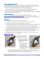
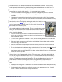
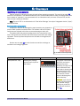
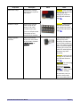
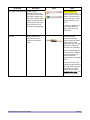
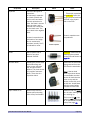
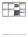
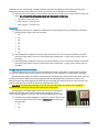
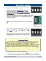
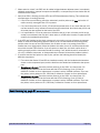
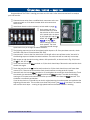
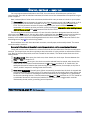
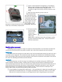
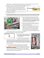
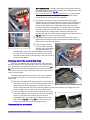
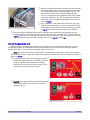
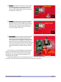
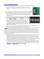
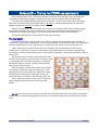
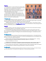
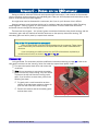
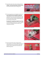
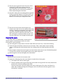
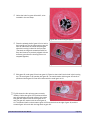
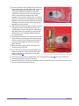
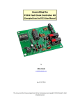
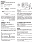
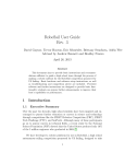
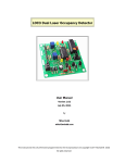
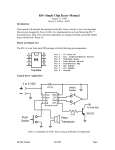
cable location – several feet, if necessary. Wire color is not important. Cat 5 Ethernet cable with solid wires is ideal, and one length of cable yields pigtails for four clocks. Cut one wire about ½" shorter than the other. Strip 1/8" of insulation from one end of each wire and form the ends into "J" hooks. Tin the bare wires with solder. "Tinning" means to coat the copper wire with a thin layer of molten solder. This is especially important with stranded wire, as it bonds the strands together. Fig. 31: Wires ready to tin. Clamp the movement in a vise, or otherwise secure it (you can tape it to your table). If you're using a solder sucker, place it on one of the two terminals at the end of the PCB, and heat the solder around the terminal with your soldering iron until it melts. Press the button to suck up the molten solder. Work quickly to avoid melting the plastic that holds the terminals beneath the PCB. If you're using desoldering braid, place it on the solder around one terminal, then heat the braid with your soldering iron. The hot braid will melt the solder and wick it away from the terminal; see Fig. 32. Work quickly to avoid melting the plastic that holds the terminals beneath the PCB. Repeat the unsoldering operation on the second terminal. When done, the terminals should move freely inside the PCB holes. Allow the unsoldered terminals to cool. Gently wiggle or pry the PCB upward away from the clear plastic housing. If it doesn't lift easily, probably some solder remains on one or both terminals. Fig. 32: Removing solder with desoldering braid. Remove the last of it with desoldering braid. It helps to push the pin toward the center of the hole with the braid and soldering iron while the solder is molten. Remove the PCB from the movement and discard it. Bend the leads of the 22-ohm resistor at 90° angles close to the body, one toward the left, and the other toward the right (Fig. 33). Cut each lead ¼" beyond the bend. Orient the movement as shown in Fig. 34, with the motor terminals closest to you. Lay the resistor on the clear housing so the near lead bends toward the right. Use needle nose pliers to loop this lead around the right-hand motor terminal. Solder the resistor to the terminal. The other resistor lead should point toward the hole in the housing. Fig. 33: Resistor leads bent 90°. It is vital that the resistor lies flat against the housing before soldering. It must be below the top of the motor terminals. Important! Glue the resistor. Sometimes heating the motor terminals loosens them in the plastic housing. It is possible that the right-hand terminal will rotate after soldering the resistor to it. If the terminal rotates too far, the fine motor wire connected to it inside the housing will break, rendering the movement useless. FCC4 Fast Clock Controller User Manual Fig. 34: Resistor soldered. Page 40