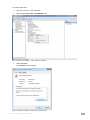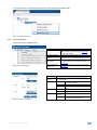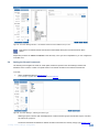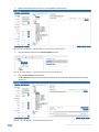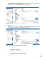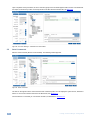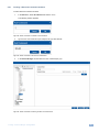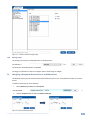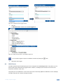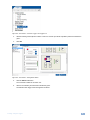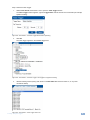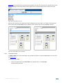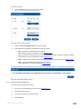
1
KRAMER ELECTRONICS LTD. PRELIMINARY USER GUIDE MODEL: Kramer K-Config Room Controller Guide Software Version 2.0.0.X Intended for Kramer Technical Personnel or External System Integrators. To check that you have the latest version, go to the DOWNLOADS section of our Web site at: http://www.kramerelectronics.com/support/downloads.asp P/N: 2900-300245 Rev 1 Contents 1 1.1 1.2 Introduction Overview System requirements: 1 1 2 2 2.1 Planning the Controlled Room Glossary 3 3 3 3.1 3.2 3.3 Kramer K-Config Software Installation Installing the “.NET Framework” Revision 2.0 Software Installing the USB Driver Installing Kramer K-Config Software 4 4 4 8 4 4.1 4.2 4.3 4.4 5 5.1 5.2 5.3 5.4 5.5 Getting to Know K-Config Initially Importing the Drivers The Main Window The K-Config Menus Quick Access Icons The Driver Manager – Getting Started Getting to Know the Driver Manager Selecting the Driver Manager The Commands Tree Editor (Commands Hierarchy) Setting the Shared Commands Serial Commands 10 11 13 17 23 24 24 27 30 33 36 6 6.1 7 7.1 7.2 7.3 8 8.1 8.2 8.3 8.4 8.5 8.6 8.7 Defining the Control Room via the Project Navigator The Virtual Device Assigning the Peripheral Devices to Master and Auxiliary Device Ports Assigning a Peripheral Device Driver to an RS-232 / RS-485 / IR Port Setting the Functionality of the GPI/O Port Assigning a Peripheral Device Driver to an Ethernet Port Using the Triggers The Custom Events Keypad Events Monitor Events GPI/O Events Timer Events Query Events Sub Routines 52 58 62 64 67 69 72 73 76 80 81 83 91 95 9 9.1 9.2 9.3 9.4 9.5 9.6 9.7 9.8 9.9 9.10 Adding Actions to a Trigger General Instructions Adding a Port Command Adding a Port Switch Action Adding a Panels Status Action Adding a Switcher Command Adding a Power Amplifier Timer Start/Stop Delay Adding Sub Routines Site Control Message 98 99 100 103 104 111 111 112 112 112 113 10 10.1 10.2 10.3 10.4 10.5 10.6 10.7 Connecting to the Device Connecting Methods Set the K-NET IDs Firmware Upgrade Device Settings Window Syncing the Configuration to the Device Reading the Configuration from the Device Clear Configuration from Device 116 116 120 122 124 129 130 131 Figures Figure 1: Media Room Components List Figure 2: USB Driver Installation –USB Installation Attempt Figure 3: USB Driver Installation – Select USB Driver Properties Figure 4: USB Driver Installation –USB Driver Properties Window Figure 5: USB Driver Installation – USB Driver Update Figure 6: USB Driver Installation – USB Driver Location Figure 7: USB Driver Installation – Windows Security Figure 8: USB Driver Installation – USB Driver Updated Figure 9: USB Driver Installation –USB Recognized on PC Figure 10: Setting a Working Directory Figure 11: Change the Working Directory Window Figure 12: Drive Database Loaded Figure 13: Installation Complete Figure 14: Opening K-Config Figure 15: Driver Database Notice Figure 16: Devices XMLs Notice K-Config – Contents 3 4 5 5 6 6 7 7 8 8 9 9 9 10 10 11 i Figure 17: The Drivers Tree Figure 18: Import Drivers Window Figure 19: Drivers Tree (with Imported Drivers) Figure 20: Opening K-Config Default Layout for the First Time Figure 21: Dragging the Triggers Window Figure 22: Drag and Drop Tool Figure 23: Triggers Window Repositioned Figure 24: Customized window setup Figure 25: Adding the Port Manager Window to the K-Config Layout Figure 26: The Port Manager Window Added to the K-Config Layout Figure 27: The File Menu Figure 28: New Project Warning Figure 29: Open a Project Figure 30: Saving a Project Figure 31: Import Devices Figure 32: Import Devices – Message Figure 33: Select Virtual Device to Save Figure 34: Export Device xml File Figure 35: Export Device xml Figure 36: The Device Menu Figure 37: The Connect Window Figure 38: The Window Menu Figure 39: Window Menu – Web Settings Window Figure 40: The About Menu – K-Config Figure 41: The Quick Access Toolbar Figure 42: Selecting the Driver Manager in the File Menu Figure 43: The Drivers Tree Figure 44: Selecting a Sony Driver Figure 45: The Driver Manager Window Figure 46: Driver Details Summary PDF File Figure 47: The Commands Tree Editor Window (Commands) Figure 48: The Commands Tree Editor Window (Tables) Figure 49: The Commands Tree Editor Window (Queries) Figure 50: The Commands Tree Editor Window – Adding a Non-default Shared Command Figure 51: The Commands Tree Editor Window – Add Command Window Figure 52: The Commands Tree Editor Window – Adding the Command Name Figure 53: The Driver Manager Window – Non-Default Shared Command Added to the Input List Figure 54: The Driver Manager – Selecting the Device Type Figure 55: The Driver Manager – Selecting PWR_ON from the Power Command Group Figure 56: The Driver Manager – Copying PWR_ON from the Command Name box Figure 57: The Driver Manager – the Non Shared Command Group Figure 58: The Driver Manager – Changing the "Power: On" Command Name Figure 59: The Driver Manager –PWR_ON added to the Power Command Group Figure 60: The Driver Manager – Standard Commands Added Figure 61: Serial Commands Figure 62: Serial Commands –Add New Command Name Figure 63: Serial Commands –the New Command Name Figure 64: Serial Commands –Selecting the New Command Name Figure 65: Serial Commands –New Command Added Figure 66: Testing Serial Commands –Connecting the PC to the Room Controller Figure 67: Testing Serial Commands –Selecting a Device Port Figure 68: Testing Serial Commands –Ethernet Settings for Auxiliary Device Figure 69: Testing Serial Commands –Successful Response Figure 70: Testing Serial Commands –Response Failure Figure 71: IR Commands – Adding a Command Figure 72: IR Commands - Connect to the Device Figure 73: IR Commands – The device is Connected Figure 74: IR Commands – The IR command String Obtained Figure 75: IR Emitter Wiring Figure 76: Serial Reply Commands – Selecting a Serial Reply Command Figure 77: Serial Reply Commands – Reading the Serial Reply Command Figure 78: The Driver Manager Window – New Table Figure 79: The Driver Manager Window – Select Number of Rows Figure 80: The Driver Manager Window – Select Number of Rows Figure 81: The Driver Manager Window – Writing the Commands Figure 82: The Driver Manager Window – Selecting every 3 Rows Figure 83: The Driver Manager Window – Logarithmic Row Selection Figure 84: The Driver Manager Window – Setting the LED Levels Figure 85: The LampHour Query Details Figure 86: The Project Navigator Window Figure 87: Adding a Master Device to the Project Navigator Window Figure 88: Main Window after Selecting the Master Device Figure 89: The Port Manager Window for RC-74DL Figure 90: The Auxiliary Device Window Figure 91: The Action Editor for RC-74DL and RC-63DL Figure 92: Adding a Virtual Device Figure 93: The Basic Virtual Device Front Panel Figure 94: The Virtual Device Properties Window Figure 95: Custom Virtual Device Appearance in K-Config Figure 96: Editing the Virtual Device Appearance (Step 1) ii 11 12 12 13 14 14 15 15 16 16 17 17 18 18 19 19 20 20 21 21 21 22 22 23 23 27 27 28 28 29 30 31 31 32 32 32 33 33 34 34 34 35 35 36 36 37 37 37 38 39 39 39 40 40 41 41 42 43 43 44 44 45 46 46 47 47 48 48 51 52 53 53 54 54 55 58 59 59 60 60 K-Config – Contents Figure 97: Editing the Virtual Device Appearance (Step 2) Figure 98: The “DVD Control” Virtual Device Front Panel Figure 99: Setting the LCD and Button Label Names Figure 100: Final Appearance of the “DVD Control” Virtual Device Front Panel in K-Config Figure 101: The Control Room Example Figure 102: Select the Port Manager Figure 103: The RC-74DL Port Manager Figure 104: The Drivers Tree Window Figure 105: Select the Driver Figure 106: Assigning a Driver to a Port Figure 107: Writing the Port Description Figure 108: Serial Settings Window Figure 109: Action Editor – Automatic Driver Selection Figure 110: Project Navigator – Display of the Assigned Drivers Figure 111: Port Manager – Master RC GPI/O ports Figure 112: Port Manager – Selecting Digital Input for a Temperature Sensor Figure 113: GPI/O Threshold Window Figure 114: The GPI/O Defined as Digital Output Figure 115: Ethernet Settings Example Figure 116: Set Volume Properties Figure 117: Selecting the EDID File Figure 118: Loading the EDID File Figure 119: EDID File Uploaded Figure 120: The Standard Built-in Triggers List Figure 121: Custom Events – Selecting the Device Startup Trigger Figure 122: Custom Events – Selecting the Power On Command Figure 123: Custom Events – Command added to the Action List Figure 124: Custom Events – Add a New Trigger Figure 125: Custom Events – Add a New Trigger Name Figure 126: Custom Events – K-Config Message Figure 127: Custom Events – The Scheduling Window Figure 128: Custom Events – The Scheduling Example 1 Figure 129: Custom Events – The Scheduling Example 2 Figure 130: Keypad Events – Selecting a Button Figure 131: Keypad Events – Setting the Button Behavior Figure 132: Select the Button Behavior Figure 133: Button Trigger Properties Window (Activate while Pressed) Figure 134: Button Trigger Properties Window (Toggle 1-2-3-4) Figure 135: The Toggle Number in the Action List Figure 136: Button Trigger Properties Window (States) Figure 137: The State Number in the Action List Figure 138: The Monitor Events Trigger Window Figure 139: Adding a Monitor Event to the Available Triggers List Figure 140: GPI/O Events – Port Manager Setup Figure 141: GPI/O Events – GPI/O in Project Navigator Figure 142: GPI/O Events – GPI/O Trigger Properties Figure 143: GPI/O Events – Digital Input: Selecting the GPI/O Port and Behavior Figure 144: GPI/O Events – Setting the Timeout Figure 145: GPI/O Events – Analog Input: Selecting the GPI/O Port and Behavior Figure 146: Timer Events – Timer Trigger Flowchart: Power ON Example Figure 147: Timer Events – Adding the Trigger Name and Timeout Figure 148: Timer Events – the Timer Trigger in the Triggers List Figure 149: Timer Events – adding Button Status Figure 150: Timer Events – the Timer Trigger Action List Figure 151: Timer Events – Projector Power On Command in the Button Trigger Action List Figure 152: Timer Events – Selecting the Timer Start/Stop Action Figure 153: Timer Events – Selecting the Timer Start/Stop Action (Start State Selected) Figure 154: Timer Events – Active Button Trigger Action List Figure 155: Timer Trigger – Add the Monitor Event Figure 156: Timer Trigger – Monitor Event Action List Figure 157: Timer Events – Timer Trigger Flowchart: Inactivity Example Figure 158: Timer Events – the Timer Trigger Name Window (Inactivity) Figure 159: Timer Events – the Timer Trigger in the Triggers List (System Inactivity) Figure 160: Timer Events – Timer Trigger Action List Figure 161: Timer Events – Button 1 Action List Figure 162: Timer Events – Add the Stop Timer Action Figure 163: Timer Events – Move the Stop Timer Action Figure 164: Timer Events – Add the Start Timer Action Figure 165: Timer Events – Button 1 Action List with Timer Triggers Figure 166: Query Events – The Query Events Window Figure 167: Query Events – Select the Query Figure 168: Query Events – The Query Results Figure 169: Query Events – Select the Query Results Figure 170: Query Events – The Power-On Trigger Figure 171: Query Events – Creating Several Query Triggers Figure 172: Sub Routines – Create a new Action Group Trigger Figure 173: Sub Routines – Set the Sub Routine Trigger Name Figure 174: Sub Routines – Set the Action Group Trigger Name Figure 175: Sub Routines – Selecting the Action Group Trigger in the Action Editor Figure 176: Sub Routines – Sub Routine Trigger is added to an Event Trigger K-Config – Contents 60 61 61 61 62 62 63 64 64 65 65 65 66 66 67 67 68 69 69 70 70 71 71 72 73 74 74 74 75 75 75 76 76 77 77 77 78 78 78 79 79 81 81 82 82 82 82 83 83 84 84 85 85 86 86 86 87 87 87 88 88 89 89 89 90 90 90 91 91 92 93 93 94 94 95 95 95 96 96 97 iii Figure 177: The Action Editor Figure 178: Selecting the Port Command Action Type Figure 179: Selecting the Command Figure 180: The New Command in the Action List Figure 181: The Action List for the All On Trigger Figure 182: The All On Trigger (after adding commands to the action list) Figure 183: The Table Port Command Figure 184: The Table Port Command – Setting a specific Volume Level Figure 185: The Table Port Command – Added to the Action List Figure 186: Selecting the Port Switch Action Type Figure 187: Port Switch Action Type added to the Action List Figure 188: Panels Status Action Editor Figure 189: Panels Status Action List Figure 190: Panels Status Action List Names Figure 191: Panels Status – Selecting a Button Figure 192: Panels Status – Selecting a Button Figure 193: Panels Status – Button Color and Behavior Selected Figure 194: Panels Status – Setting the LCD Label Figure 195: Panels Status –LCD Label Added Figure 196: Panel Status – LEDs Light States Figure 197: Panel Status – Panel Lock Figure 198: Panel Status – Locking the Front Panel Buttons Figure 199: Switcher Command – Select an Input Figure 200: Power Amplifier – Select an input Figure 201: Delay – Set the Delay Time Figure 202: Sub Routines – Select a Sub Routine Figure 203: Site Control Message – Select the Query Event Figure 204: Site Control Message – Action Group Trigger is added to an Event trigger Figure 205: Site Control Message – Select Port and Query Figure 206: Site Control Message – Select the Status Figure 207: Site Control Message – Type the Message Figure 208: Connection Method Window Figure 209: Configuration Mismatch Warning Figure 210: Local Area Connection Properties Window Figure 211: Internet Protocol Version 4 Properties Window Figure 212: Internet Protocol Version 6 Properties Window Figure 213: Internet Protocol Properties Window Figure 214: KNET ID – A Controlled Room Setting Example Figure 215: KNET ID – Connect the Device Directly to PC Figure 216: KNET ID – The K-NET ID Connect Window Figure 217: KNET ID – Setting K-NET ID Figure 218: KNET ID –K-NET ID assigned Figure 219: Firmware Update Window Figure 220: Load Firmware Upgrade Window Figure 221: Firmware Upgrade Warning Figure 222: Firmware Upgrade Process Figure 223: Firmware Upgrade Successful Figure 224: Firmware Upgrade Process Complete Figure 225: General Device Settings Figure 226: Selecting an auxiliary device Figure 227: Auxiliary Device Settings Figure 228: Ethernet Settings Figure 229: Security Settings Figure 230: Date and Time Settings Figure 231: Loading a Configuration Figure 232: Write Configuration warning Figure 233: Writing and Device Resetting Process Figure 234: Writing Complete 99 100 100 101 101 101 102 102 103 103 103 104 105 105 106 106 107 108 108 109 110 110 111 111 112 112 113 113 114 114 115 117 117 118 119 119 120 121 121 121 122 122 122 123 123 123 124 124 125 125 126 126 126 127 129 130 130 130 Trademarks: © 2014 Kramer Electronics Ltd. All rights reserved. Microsoft and Windows are either registered trademarks or trademarks of Microsoft Corporation in the United States and/or other countries. Android is a trademark of Google Inc. iOS is a registered trademark of Apple Inc. iv K-Config – Contents 1 Introduction You are here: Configuration Steps Introduction Planning Installation Introduction to K-Config Driver Manager Project Navigator Port Manager Triggers Adding Actions Connecting to a Device Description General information and system requirements Carefully plan your controlled room Install the Software Get to know the K-Config main window, menus and quick access icons Define the Peripheral Device Drivers Define the Controlled Room Assign the peripheral devices to the Master and Auxiliary device ports Activate the Triggers Describes how to add the various actions to a trigger Describes how to connect to a device, upgrade the firmware, read/write to the device and so on Section 1 2 3 4 5 6 7 8 9 10 Welcome to Kramer Electronics! Since 1981, Kramer Electronics has been providing a world of unique, creative, and affordable solutions to the vast range of problems that confront video, audio, presentation, and broadcasting professionals on a daily basis. In recent years, we have redesigned and upgraded most of our line, making the best even better! Our 1,000-plus different models now appear in 11 groups that are clearly defined by function: GROUP 1: Distribution Amplifiers; GROUP 2: Switchers and Routers; GROUP 3: Control Systems; GROUP 4: Format/Standards Converters; GROUP 5: Range Extenders and Repeaters; GROUP 6: Specialty AV Products; GROUP 7: Scan Converters and Scalers; GROUP 8: Cables and Connectors; GROUP 9: Room Connectivity; GROUP 10: Accessories and Rack Adapters and GROUP 11: Sierra Video Products. Congratulations on purchasing your Kramer Room Controller device, which is ideal for controlling A/V equipment and media room items. The configuration software is part of the package and includes the Kramer K-Config Guide. The Kramer K-Config software lets you set a sequence of actions in a trigger (a macro) and assign them to any of the configurable buttons on any of the relevant RC devices, a schedule or an event. i Note that the RC buttons can be configured prior to installation. This online guide accompanies the K-Config application software for Kramer room controllers and is compatible with previous versions. Download up-to-date Kramer user manuals and guides from the Internet at this URL: http://www.kramerelectronics.com 1.1 Overview K-Config is an intuitive configuration application that easily maintains control driver libraries, creates room control macros and protocols, and automatically generates HTML files where applicable. K-Config supports a revised GUI, adds a host of advanced and easy to use features and uses a revamped driver database. The easy workflow shared between all Kramer control products enables a “Learn once – use forever” approach. The K-Config: Is a simple to use Graphical User Interface design, and no programming knowledge is required Is powerful and updateable by the user driver database Features a flexible querying system for projectors lamp hours, fans status and similar information Includes an easy-to-use messaging system all the way to the Site-CTRL AV site monitoring application Enables integration with touch based control devices through the K-Touch system Is compatible with current Windows versions: Windows 7 and Windows 8 K-Config – Introduction 1 1.2 System requirements: This section defines the minimum requirements for the Kramer K-Config and describes how to install your system. 1.2.1 System Requirements for the Kramer K-Config The system minimum requirements include: 1.2.2 1GHz or faster processor 1GB or more RAM At least 1GB free hard disk space Network connection for configuring devices or USB Microsoft.NET® Framework 3.5, automatically installed (see Section 2.1) Operating Systems Microsoft® Windows XP®, Microsoft Windows 7 (32 or 64 bit) or Microsoft Windows 8 (32 or 64 bit) are the recommended operating systems (Windows NT does not support .NET 2.0 and cannot be used). Other Windows versions are not supported. 2 K-Config - Introduction 2 Planning the Controlled Room You are here: Configuration Steps Description Section Introduction Planning Installation Introduction to K-Config Driver Manager Project Navigator Port Manager Triggers Adding Actions Connecting to a Device General information and system requirements Carefully plan your controlled room Install the Software Get to know the K-Config main window, menus and quick access icons Define the Peripheral Device Drivers Define the Controlled Room Assign the peripheral devices to the Master and Auxiliary device ports Activate the Triggers Describes how to add the various actions to a trigger Describes how to connect to a device, upgrade the firmware, read/write to the device and so on 1 2 3 4 5 6 7 8 9 10 Carefully plan your room controller system layout to ensure a smooth and easy configuration and installation (refer to the separate user manuals), by: Defining your requirements Listing the peripheral devices and room items that will be included in the system Planning the location of each device Planning the function of each device Make a detailed list of the functions and commands required of the system devices, for example: Figure 1: Media Room Components List Once this list is finalized and approved you can proceed with the configuration and installation process. i 2.1 Note that you can create a configuration file for a certain control setup without connecting the relevant Master or room controller to your PC (dry configuration). Glossary The glossary in the table below defines common terms used throughout this manual: Glossary Action Action Types Action List Driver Port Manager Trigger GPI/O A command that performs an action (for example, Mute the sound on the power amplifier). Actions are grouped into Action Types based on their function (for example, Button Light) Select an Action Type from the list to display its available ports and commands (for example, selecting the Relay command lists the ports and actions relevant for this action type) A list of actions which will be performed one after another in the order they were added to the action list. An action list will be performed as a result of a Trigger. A communication protocol that allows Kramer’s control products to communicate with a hardware peripheral, for example, a projector The Port Manager window lists the available ports, lets you write a description and assign a default driver for each port, as well as determine which port will appear in the Web Access Main page An event which will start the execution of an Action List. There are several types of triggers which can be used – Button press, knob rotation, Scheduled event, Monitor Event and so on General Purpose Input/Output is a port that can be configured by the K-Config software in several ways and is usually used to interact with common room sensors (such as an occupancy sensor, temperature sensor and so on) K-Config – Planning the Controlled Room 3 3 Kramer K-Config Software Installation You are here: Configuration Steps Introduction Planning Installation Introduction to K-Config Driver Manager Project Navigator Port Manager Triggers Adding Actions Connecting to a Device Description General information and system requirements Carefully plan your controlled room Install the Software Get to know the K-Config main window, menus and quick access icons Define the Peripheral Device Drivers Define the Controlled Room Assign the peripheral devices to the Master and Auxiliary device ports Activate the Triggers Describes how to add the various actions to a trigger Describes how to connect to a device, upgrade the firmware, read/write to the device and so on Section 1 2 3 4 5 6 7 8 9 10 To install the K-Config software, do the following: 3.1 Check that “.NET Framework” Revision 4.0 software is installed or install it if it is missing (see Section 3.1) Install the USB driver (see Section 3.2) Install the Kramer K-Config software (see Section 3.3) Installing the “.NET Framework” Revision 2.0 Software Prior to using the Kramer K-Config software, make sure that the “.NET Framework” Revision 4.0 software is installed on your PC. If it is not, you need to install it: 3.2 If you have a fast Internet connection, this software is automatically installed during the installation of the Kramer K-Config software Installing the USB Driver If you wish to configure the RC device by connecting it via a USB cable, you need to download and install the USB driver. Download the Kramer USB driver from the installation disc or from our Web site at http://www.kramerelectronics.com/support/downloads.asp, save it on your PC and extract the zip file to a directory where you can find it later. Connect the mini USB cable from your PC to the device and wait until Windows 7 completes the connection and will report in a bubble that "Device driver software was not successfully installed" (If the device driver is installed successfully, skip the rest of section). Figure 2: USB Driver Installation –USB Installation Attempt 4 K-Config - Kramer K-Config Software Installation To install the USB driver: 1. Open Control Panel -> Device Manager … 2. Right click the Kramer USB –COM DEVICE driver: Figure 3: USB Driver Installation – Select USB Driver Properties 3. Select Properties. The Properties window appears: Figure 4: USB Driver Installation –USB Driver Properties Window K-Config – Kramer K-Config Software Installation 5 4. Click the Update Driver… window. The following window appears: Figure 5: USB Driver Installation – USB Driver Update 5. Select Browse my computer for driver software and then set the location of the driver on your PC: Figure 6: USB Driver Installation – USB Driver Location 6 K-Config - Kramer K-Config Software Installation 6. Click the Next button. The Windows Security window appears: Figure 7: USB Driver Installation – Windows Security 7. When the installation is completed, the following window appears: Figure 8: USB Driver Installation – USB Driver Updated The PC recognizes the USB port to which the device is connected. K-Config – Kramer K-Config Software Installation 7 Figure 9: USB Driver Installation –USB Recognized on PC 3.3 Installing Kramer K-Config Software To download Kramer K-Config from the Internet (note that file names are liable to change from time to time): 1. Go to http://www.kramerelectronics.com/support/downloads.asp and download the file: “Kramer K-Config.zip” from the DOWNLOADS section. 2. Extract the file “Kramer K-Config.zip” package, which includes the Kramer K-Config application setup and the Kramer device drivers, to a folder (for example, C:\Program Files\Kramer K-Config). 3. Install the Kramer K-Config application. 4. Click OK. The following window appears (see Figure 10): Figure 10: Setting a Working Directory 5. Select or create a new working directory (see Figure 11). The working directory will keep the information that is essential for operating the software. This information will remain unchanged while upgrading the software 8 K-Config - Kramer K-Config Software Installation Figure 11: Change the Working Directory Window 6. If you need to change the working directory, click the Browse For Folder button, select the working directory and click OK. If you do not need to change the working directory, go to the next step. 7. Once the working directory is selected, click the Set to Default Location button. If a previous version of K-Config is installed, the drivers are already uploaded Figure 12: Drive Database Loaded 8. Continue to run the setup according to the installation instructions. The following Window Appears: Figure 13: Installation Complete 9. Click Close to complete Installation. K-Config – Kramer K-Config Software Installation 9 4 Getting to Know K-Config You are here: Configuration Steps Introduction Planning Installation Introduction to K-Config Driver Manager Project Navigator Port Manager Triggers Adding Actions Connecting to a Device Description General information and system requirements Carefully plan your controlled room Install the Software Get to know the K-Config main window, menus and quick access icons Define the Peripheral Device Drivers Define the Controlled Room Assign the peripheral devices to the Master and Auxiliary device ports Activate the Triggers Describes how to add the various actions to a trigger Describes how to connect to a device, upgrade the firmware, read/write to the device and so on Section 1 2 3 4 5 6 7 8 9 10 Following the installation, you can click the K-Config icon to open the software: Figure 14: Opening K-Config The Driver Database Notice appears if K-Config is opened for the first time: Figure 15: Driver Database Notice If you are opening K-Config for the first time, the driver data base is empty and you need to download the drivers. For Kramer product drivers, click the link in this window to download the drivers from the Kramer Web site and then you can import the drivers. In the same way download the drivers of other peripheral devices (see Section 4.1). 10 K-Config - Getting to Know K-Config If you have not yet loaded the Kramer list of master/auxiliary devices, the following message appears: Figure 16: Devices XMLs Notice Download the xml files from the Kramer Web site and then import them by selecting Import Devices from the File menu (Section 4.3.1.4). 4.1 Initially Importing the Drivers The peripheral devices installed in the controlled room have device drivers that let them communicate with computers. The device driver needs to be installed so that the room controller can recognize it and control it. The Kramer K-Config software uses driver commands to control these peripheral devices. Check—according to your list of peripheral devices—that you have all the required drivers: Kramer machines have drivers that are provided within the package Other peripheral device drivers are obtained via their manufacturer To import the drivers: 1. Download the required drivers to a folder, for example, C:\Media-Room-1\Peripheral Device Drivers. 2. From the File menu, click Driver Manager (or use the quick access icon). The Drivers Tree window appears. Figure 17: The Drivers Tree K-Config – Getting to Know K-Config 11 3. Click the Import Drivers button to import drivers. The following window appears: Figure 18: Import Drivers Window 4. Select the files to import and click OK. The imported drivers are arranged in the expanded Drivers Tree as follows: Figure 19: Drivers Tree (with Imported Drivers) 12 K-Config - Getting to Know K-Config 4.2 The Main Window The K-Config main window is modular and can be altered according to your needs. You can change the size and location of each window in the layout separately, replace it, delete it or add other windows. The K-Config main window default layout includes the: The main window incorporates the five most frequently used windows: Project Navigator – shows the control room configuration, including peripheral devices Triggers – shows the list of available triggers, arranged in Event categories Action list – shows the list of actions in a selected trigger Device View – the front panel view of the selected device Action Editor – lets you create an action to add to the action list The remaining optional windows which are not accessed as often appear in the Windows menu and include the: Port Manager – lets you assign drivers and other characteristics to the ports Device Settings –general, security, Ethernet and date and time settings Web Settings –logo and Web page settings Figure 20 shows the main screen default layout appears: Figure 20: Opening K-Config Default Layout for the First Time Each user can tailor the main screen appearance according to his/her work flow and needs. To facilitate this, the windows in the main screen can be dragged and positioned to a different location via the drag and drop tool (illustrated Figure 21). For example, to move the Triggers window in the main screen, drag the Triggers window away from its current location (see Figure 22). K-Config – Getting to Know K-Config 13 Figure 21: Dragging the Triggers Window Select the new location by moving the Triggers window towards one of the drag and drop tool circled in Figure 22: Figure 22: Drag and Drop Tool 14 K-Config - Getting to Know K-Config For example, to place the Triggers window at the left, drag the Triggers window to the left drag and drop tool. The Triggers window appears at the left: Figure 23: Triggers Window Repositioned In the same way you can move the selected window to be in a separate first/last row, between other windows in the row or the first/last column. The main screen can have an appearance that is different than the default layout and is suited for your use, as shown in the example in Figure 24: Figure 24: Customized window setup K-Config – Getting to Know K-Config 15 In the same way you can also add additional windows, for example, the Port Manager window, as illustrated in the example in Figure 25. Select Port Manager from the Windows menu and click the drag and drop tool: Figure 25: Adding the Port Manager Window to the K-Config Layout The Port Manager window is added to the main window: Figure 26: The Port Manager Window Added to the K-Config Layout The same setup will reappear the next time you launch K-Config. At any time you can reset to the factory default view by clicking Default Layout in the Windows menu. 16 K-Config - Getting to Know K-Config 4.3 The K-Config Menus This section describes the K-Config menus. 4.3.1 The File Menu This section defines the File Menu: Menu Command New Project Open Project Save Project Save Project As Auto Save Project Export Configuration Set Working Directory Driver Manager Import Devices Figure 27: The File Menu Export Device Recent Projects Exit Function Click to create a new project, see Section 4.3.1.1 A project includes the configuration as well as the drivers Open an existing project, see Section 4.3.1.2 Click to save the current project, see Section 4.3.1.3 Save the project under a different name You can choose to save the project automatically (yes) or not (no) For using batch configuration upload feature with SiteCTRL When exporting a configuration, the file name automatically includes the master room controller name and the date it was saved. For example, SL-10-Configuration-Sep10.kpt Click to set the working directory You can change the working directory any time Click to open the Driver Manager window Click to import a new or existing devices XML, see Section 4.3.1.4 You can import one or several new and/or revised device layouts to K-Config and virtual device layouts created in other K-Config installations Click to export a device, Section 4.3.1.4 You can export virtual device layouts to other K-Config installations or to the K-touch virtual device screen designer system Click to display the recent projects you have been working on. Note that recent projects will not be saved when installing a new software revision Click to exit the program 4.3.1.1 Starting a New Project To start a new project, do the following: 1. Select New Project in the File menu, the following window appears (if you are not using K-Config for the first time): Figure 28: New Project Warning K-Config – Getting to Know K-Config 17 4.3.1.2 Opening an Existing Project To open a project, select Open Project in the File menu. If the saved project contains device drivers with same command name but different command syntax the following window appears: Figure 29: Open a Project After clicking one of the above options (Yes/Yes to All/No/No to ALL), the following window appears: Click OK 4.3.1.3 Saving a Project To save the project, click Save or Save Project As in the File menu. The following window appears: Figure 30: Saving a Project 18 K-Config - Getting to Know K-Config When saving, writing or opening a new project, follow these important rules: In order to make uploading the project as stable as possible, projects are saved automatically before writing a configuration to a device. This behavior may overwrite the existing project. If you want to keep the previous configuration as well, be sure to rename the project before writing it to the device Always change a project name via Save Project As in the software. If the project name is changed outside the K-Config software (for example, via the Rename function in a Windows folder view), it will not open correctly in K-Config When quitting K-Config, the open project will not be saved automatically. If needed, save the open project before quitting K-Config 4.3.1.4 Import/Export Devices K-Config lets you import or export device XML templates via the Import/Export Device feature in the File menu. This feature lets you import a newly released control device to the Control Room list (Master/Auxiliary) without having to upgrade the K-Config. You can also share virtual device layouts that were created in K-Config by exporting and importing them to a different room installation. To Import a device: 1. Select Import Devices in the File menu, and select the device (or devices) you want to import (only Kramer xml files will appear on the list). The following window appears: Figure 31: Import Devices 2. Click Open. If the device already exists on your list, you will get the following message: Figure 32: Import Devices – Message Otherwise, the device will be added to the list. K-Config – Getting to Know K-Config 19 To export a device: 1. Select Export Device in the File menu, and select the device (or devices) you want to export. The following window appears: Figure 33: Select Virtual Device to Save 2. Click OK. The following window appears: Figure 34: Export Device xml File 20 K-Config - Getting to Know K-Config You can also export a virtual device by right clicking it and selecting Export Device XML: Figure 35: Export Device xml 4.3.2 The Device Menu This section defines the Device menu. Menu Command Connect/ Disconnect Firmware Upgrade Sync Configuration to Device Read Configuration from Device Figure 36: The Device Menu Clear Configuration from Device Feature Connection Method Ethernet Area Serial USB Area Function Click to connect to a device via an IP number, a USB connector or a serial port (see Figure 37) or disconnect the device Load file for firmware upgrade (see Section 10.2). Writes the configuration to the device (active only when the device is connected), see Section 10.5 Reads the configuration from the device (active only when the device is connected via ETH), see Section 10.6 Removes the configuration from the device, see Section 10.7 Function Check to select connection to the device via the Ethernet, USB or Serial port Type the IP address of the device to which IP: you want to connect Port: Shows the port number Click to reset the IP address to its default Default: value Port: Select the communication port Baudrate: Set the baud rate USB Device Select the communication USB port Drop box: Refresh Ports: Click to check if there are ports ready to connect on the Kramer device Figure 37: The Connect Window K-Config – Getting to Know K-Config 21 4.3.3 The Windows Menu The Windows menu lists layout operations and all the available windows. Some of the windows (checked in the Windows menu) appear in the default layout. At any time you can add or delete a window from the main window layout and by clicking Default Layout you can return to the default layout. Menu Command Save Layout Load Layout Default Layout Save Layout on Exit Default Project Navigator layout Triggers windows Action List Action Editor Device View Port Manager Device Settings Web Settings Function Saves the current windows layout Load a saved layout Set to the default layout Set to On to save Set the controlled room devices Arrange the triggers Lists the actions added to the trigger Select the actions to add to the trigger Displays the selected device front panel Click to open the Port Manager window Click to open the Device Settings window see Section 10.4) Click to open the Web Settings window (see Section 4.3.3.1) Figure 38: The Window Menu 4.3.3.1 Web Settings Web settings are used to set the Web page logo, room name and so on for Master room controllers that have an ETH port for remote access from a browser (and by that are also Site-CTRL compatible). Figure 39 shows the Web Settings window: Figure 39: Window Menu – Web Settings Window The logo file type can be either jpg, jpeg or png, up to 500 Kbytes in size. For best image quality, when viewed on the device’s Web pages, we recommend that you use images of H 200px and W 790px pixels. i 22 Kramer Site-CTRL is a powerful A/V assets management tool. It offers real-time monitoring and control of Kramer Master controllers installed in an A/V site and the A/V equipment connected to them. The Kramer Site-CTRL downloadable version can monitor and control up to 100 Kramer Master controllers. K-Config - Getting to Know K-Config Kramer Site-CTRL: 4.3.4 Generates a single page summary of the entire installed A/V site Reports the communication status for each room Reports the status of the local display devices Reports the remaining lamp life for projectors Supports easy access to the built-in Web pages of Master controllers via Web Access Raises alerts and sends e-mails when prompted by a user-defined special event The About Menu The About menu displays the basic software and company details: Figure 40: The About Menu – K-Config 4.4 Quick Access Icons The K-Config main window includes a quick access and status toolbar, located just below the menus: Figure 41: The Quick Access Toolbar Quick Access Items Function Click to open a new project Click to open an existing project Click to save the current project Click to open the Driver Manager Click the button to connect to the device Shows the device connection status Click the button to sync the current configuration to the device (after connecting it to the PC) K-Config – Getting to Know K-Config 23 The Driver Manager – Getting Started 5 You are here: Configuration Steps Introduction Planning Installation Introduction to K-Config Driver Manager Project Navigator Port Manager Triggers Adding Actions Connecting to a Device 5.1 Description General information and system requirements Carefully plan your controlled room Install the Software Get to know the K-Config main window, menus and quick access icons Define the Peripheral Device Drivers Define the Controlled Room Assign the peripheral devices to the Master and Auxiliary device ports Activate the Triggers Describes how to add the various actions to a trigger Describes how to connect to a device, upgrade the firmware, read/write to the device and so on Section 1 2 3 4 5 6 7 8 9 10 Getting to Know the Driver Manager Peripheral AV devices (such as projectors, DVD players, switchers, scalers and so on) are controlled by sending out an appropriate command from the controller to the unit, over serial, ETH or IR interfaces. A Driver is a collection of these commands which includes all the relevant commands for the specific device. In this version of K-Config, the Driver Database was improved so it will better reflect the similarities between different devices and by that make several configuration tasks simpler and easier. Due to the changes in the driver database structure, when importing into this version a driver that was already created in an earlier version of K-Config, we suggest that you make some modifications to the driver before using it (see Section 5.1.1). When selecting “Driver Manager” from the file menu or the icon, the Drivers Tree window appears and you need to select a specific peripheral device or to open a new driver. Once selected, the Driver Manager window appears. The Driver Manager has standard command names for different devices by means of a Shared command-names structure which can be used to build a standard command list. Each command type has a shared name that is common to devices in the controlled room. A shared command can be either empty (only the name is on the list but it has no content), or full (the command has content); when the command is full, the command name on the list appears bold. The driver manager presents a list of standard shared command names. You can add a command name to the shared list. When adding a new command name to the shared sections of a driver – this command name will appear in every driver you will open in the future as an empty command name. This makes it easy to use the same command names in all your drivers. For example, if you have two types of projectors (made by different manufacturers) in the controlled room and each of them has its own specific communication protocol, they will most likely have different command names specified in their user manual for the same exact functional action. For example, the command name for powering up the projector can be named “PWR: ON” for the first projector and “Power: on” for the other one. The driver manager defines a common (or shared) name for both, “PWR_ON”, for the same type of command, while the content of the command (syntax) remains specific for each projector. i 24 Note that a command name cannot include spaces. K-Config - The Driver Manager – Getting Started The Driver Manager window is actually a generic framework for managing the controlled room; it includes sets of standard command names (Shared) within the following categories: Serial commands IR Commands Serial replies Tables (Serial range commands) Queries Each of the above categories contains sub-groups with command names that are “empty” for a new driver (a command name without any content): Figure 35: The Commands List in the Driver Manager A “Full” command name which includes syntax will appear Bold. An empty command name will appear as normal font. When selecting any of these “empty” command names you can see that the Command Syntax line is empty. K-Config – The Driver Manager – Getting Started 25 For example, when selecting PWR_ON: Figure 35: An Empty Command Line i Note that when adding a command name to one of the Shared sub categories, this command name will be added to the Serial, Serial Replies and IR sections in your command name tree and will appear as empty in all the drivers you will open for editing or as new from now on. Each of the above categories also includes a Non-Shared sub-group. The Non-shared sub-group is used for device specific command actions which are not used for other devices. Command names added to this section will not appear as empty command names in other drivers you will later open, since they are specific for this driver. When importing or opening an existing driver, the command names included in this driver are compared to the shared command names. Whenever a match between command names is found, the syntax associated with this command name will appear under the relevant shared command name. If a command name is not found in the Shared sections, it will appear in the Non-Shared section of this driver. 5.1.1 Updating Commands Names to the current version of K-Config If you were using a previous version of K-Config, we recommend that you update the command names that are used in your command tree. This can be done easily by opening the command syntax, and changing the command name to the relevant Shared command name (see Section 5.4). For example, in a certain driver the Power On function was previously tagged with the command name "POWER_ON". In the Driver Manager this command will be listed in the Non-Shared category as a non-shared command. Select this command for editing, and change the command name to “PWR_ON”. The command name changes and will move to the Shared section of this driver. i It is important that you carefully change the command names in this manner. If these commands are already used in an existing project that you may want to upload in the future to control devices, you will need to update the command names in the project itself where they are used. This framework was structured to let you standardize the command names so that all the same command types will share the same command name although the specific command content is unique for each specific device. 26 K-Config - The Driver Manager – Getting Started Furthermore, the Driver Manager lets you select the device type (for example, a projector, DVD Player, audio amplifier and so on) so that the shared commands list displayed best fits the type of device you are using. For example, it makes little sense to display Transport related commands for a Projector. It’s important to understand that the device type selected only affects the displayed command sub groups, it has no “real” influence on the command tree – all shared commands still exist even if they are not displayed. You can also select a generic type so that all the possible commands are available (see item 3 in Figure 40). If you want to add or delete command groups for the different device types you can click the Commands Hierarchy button and use the Commands Tree Editor to add or delete command groups for each device type or create a custom made device type (see Section 5.2). 5.2 Selecting the Driver Manager To open the Driver Manager do the following: 1. In the File menu select Driver Manager. Figure 42: Selecting the Driver Manager in the File Menu The Drivers Tree window appears: Figure 43: The Drivers Tree K-Config – The Driver Manager – Getting Started 27 2. Select the driver you want to edit (a Sony Driver in this example): Figure 44: Selecting a Sony Driver 3. Click Edit. The Driver Manager window appears. Figure 45: The Driver Manager Window 28 K-Config - The Driver Manager – Getting Started # Feature 1 2 3 Commands Hierarchy Button Drivers Tree Button Driver Details 4 5 6 7 8 9 10 11 Driver Settings: Serial Settings Driver Settings: Ethernet Settings Create PDF Summary Button Export Driver Button Command Names List OK button Cancel Button Apply Button Function Set the Commands Hierarchy layout (see Section 5.3) Click to access the Drivers Tree window and select a different driver The Driver Details area displays the vendor, device model and driver revision. Device Type – lets you select the typical device type from a drop down list. Each device type relates to a set of command groups that are typical for that device type. For example, Selecting DVD Player as the device type will include the Power, Transport, Image and Setup group commands For serial connections, set the baud rate, data bits, parity and stop bits For Ethernet connections, set the IP address, port and protocol Click to create the driver summary see Figure 46 Export the driver setup Includes all the command types (Default / Non Default Shared and Non-shared) Click to approve changes Click to cancel changes Click to apply changes Figure 46 shows an example of a PDF driver details summary document: Figure 46: Driver Details Summary PDF File K-Config – The Driver Manager – Getting Started 29 5.3 The Commands Tree Editor (Commands Hierarchy) Click the Commands Hierarchy button to open the Commands Tree Editor. The Commands Tree Editor gives an overall view of the Device Types, Command Groups and Commands with regard to default/non-default shared driver commands, Tables and Queries and lets you make specific adjustments. 5.3.1 IR, Serial and Replies Select IR, Serial and Replies to display the Device Types list, the Commands Group list and the Commands in each group. Figure 47 shows the IR, Serial and Replies Commands Editor. Figure 47: The Commands Tree Editor Window (Commands) # Feature Device Types Command Groups Commands i 30 Function The list includes commonly used devices to choose from. Each Device type determines command groups that are available for the selected device type (for example, Projector includes Power, Input, Volume, Image and Setup command groups while Audio Amplifier includes Power, Image, Setup and Camera command groups. You can rearrange the order of the Device type list using the up/down arrows, add a new Device Type, rename it or delete it. Once you select the device type, the relevant Command Groups are automatically checked. You can check a command group to add it to the device type or uncheck it. You can add a new Command Group, delete it or rename it. You can also check or uncheck the entire command groups list. Lists the standard commands included in command group. You can add a new Command Group (non-default shared), delete it or rename it. Note that K-Config is supplied with a number of popular command groups and command names. These cannot be changed or deleted by the user. K-Config - The Driver Manager – Getting Started 5.3.2 Tables Tables shows the list of default shared tables (see Section 5.5.4 for a more detailed explanation). You can add a new non-default shared table name, delete it or rename it: Figure 48: The Commands Tree Editor Window (Tables) 5.3.3 Queries Queries shows the list of queries (see Section 5.5.5 for a more detailed explanation). You can add a new Query Name (non-default shared), delete it or rename it: Figure 49: The Commands Tree Editor Window (Queries) K-Config – The Driver Manager – Getting Started 31 5.3.4 Adding Non-default Shared Commands Non-default shared commands can only be added via the Commands Tree Editor window. In the following example, a DVI command needs to be added to the Projector Input command group. To add this non-default shared command, do the following: 1. Click the Commands Hierarchy button and select the Input command group: Figure 50: The Commands Tree Editor Window – Adding a Non-default Shared Command 2. In the Commands list click the + icon. The following window appears: Figure 51: The Commands Tree Editor Window – Add Command Window 3. Type the new command name and click OK: Figure 52: The Commands Tree Editor Window – Adding the Command Name The new command was added to the Input Commands group and the DVI input non-shared command can be moved to the Input Commands list: 32 K-Config - The Driver Manager – Getting Started Figure 53: The Driver Manager Window – Non-Default Shared Command Added to the Input List i Note that the non-default shared commands that were added will be part of the shared list for all the drivers. Repeat this procedure for Tables and Queries in the same way. Once you have completed this, you can configure the controlled room. 5.4 Setting the Shared Commands The following section applies to Serial, IR, serial replies, tables and queries in the driver Manager window and describes how to move the content of a specific Driver’s non-shared command to the shared commands list. To do this: 1. Select the Device Type (see Section 5.3.1). In this example a projector device type was selected (see Figure 54) Figure 54: The Driver Manager – Selecting the Device Type Selecting Projector narrows down the displayed list of serial command groups and includes only the ones that are relevant to a projector. The shared commands list default/non-default command names that are currently "empty" (see Section 5.3.1). K-Config – The Driver Manager – Getting Started 33 2. Select the standard name for "Power: On" in the Power Command Group: Figure 55: The Driver Manager – Selecting PWR_ON from the Power Command Group 3. Copy the standard name from the Command Name text box: Figure 56: The Driver Manager – Copying PWR_ON from the Command Name box 4. Open the Non-Shared command group. The Non-Shared command group includes the imported device commands. Select the relevant command, "Power: On". Figure 57: The Driver Manager – the Non Shared Command Group 34 K-Config - The Driver Manager – Getting Started The Command Name and Command Syntax appear on the right side of the window. Once connected, you can test each command via the Test Command area on the lower right side. 5. In the Command Name text box, paste (or type) the standard command name: Figure 58: The Driver Manager – Changing the "Power: On" Command Name 6. Click Set. The Command name has changed: in the Power commands group, PWR_ON appears bold (it's not "empty") and "Power: On" has disappeared from the Non-Shared commands list. Figure 59: The Driver Manager –PWR_ON added to the Power Command Group 7. In the same way you can move the content of other non-shared commands and fit them into the relevant command groups: Select the shared command name Mark and copy the standard command name In the Non-Shared group, select the relevant command Paste the standard name into the Command Name box Click Set K-Config – The Driver Manager – Getting Started 35 Upon completion of this procedure, the "live" command groups and commands appear bold in the list. Commands that are unique to the device (or were not moved) remain in the Non-Shared command list, see Figure 60. Figure 60: The Driver Manager – Standard Commands Added 5.5 Serial Commands Select a serial command (Shared or Non-Shared). The following window appears: Figure 61: Serial Commands The area on the right shows the command name and command syntax. You can display the syntax as Hex, Decimal or ASCII. To move a Non-shared command to the Shared list, see Section 5.4. Once the device is connected you can test the command, as described in Section 5.5.1. 36 K-Config - The Driver Manager – Getting Started 5.5.1 Creating a Serial Non-shared Command To add a serial non-shared command: 1. In the Serial list, select Non-Shared and click the + icon The following window appears: Figure 62: Serial Commands –Add New Command Name 2. Type the new command name (for example, DVI_IN) and click OK: Figure 63: Serial Commands –the New Command Name 3. In the Driver Manager window select the new command (DVI_IN): Figure 64: Serial Commands –Selecting the New Command Name K-Config – The Driver Manager – Getting Started 37 4. Type the command and click the Set button: Figure 65: Serial Commands –New Command Added The DVI_IN command was added to the commands non-shared list and appears bold. i Note that when writing a serial command: - if you enter ASCII commands, enclose the strings in quotation marks (for example, "MUTE OFF") - Prefix the hex characters with 0x or "$" (for example, 0x0D), unprefixed values are in decimal (for example, 13) - String and byte values should be separated by commas or spaces (for example, "BRIGHT DEC",0x0D) - If a protocol command states Carriage Return (<CR>) and/or Line Feed (<LF>) following the command line, add 0x0D or 0x0A, respectively, outside the command quotation marks, separated by a comma. For example, “PWR” <CR> <LF> should appear as “PWR”,0x0D,0x0A If required, you can test the command 1. If the control device is not connected, connect it now and connect the auxiliary device (for example, a DVD or projector). 2. In the Driver Manager window select the command to be tested. The command syntax appears in the text box on the top right. 3. 38 Click the Test Command button. If the connection type between the RC and the PC was not yet established, the connection window will appear and you should select the connection method (for example, the RC-74DL is connected to the PC via the Ethernet) and click Connect (see Figure 66) after that the Device Ports window appears (see Figure 67) If the RC is connected, the Device Ports window appears and you will need to select the port to which the auxiliary device is connected (see Figure 67) K-Config - The Driver Manager – Getting Started Figure 66: Testing Serial Commands –Connecting the PC to the Room Controller Figure 67: Testing Serial Commands –Selecting a Device Port 4. Select the port to which the device is connected to the room controller (for example, the projector is connected via RS-232 Terminal Block 1 to the RC-74DL room controller) and click OK. Note that if the auxiliary device is connected to the Ethernet, the following window appears. Verify the details and then click OK Figure 68: Testing Serial Commands –Ethernet Settings for Auxiliary Device The command tested is sent to the Auxiliary device. The request text box shows the sent command and the Response text box shows the response: K-Config – The Driver Manager – Getting Started 39 Figure 69: Testing Serial Commands –Successful Response If the device fails to respond, an ERROR, TIMEOUT message appears: Figure 70: Testing Serial Commands –Response Failure 5.5.2 Creating an IR Command You can add an IR command in the same way as described in Section 5.5.1 or read the IR command via IR Learning as described in this section. To create IR commands for a selected device, connect the RC device (with IR learning capability) directly, whether it is defined as an auxiliary device or a Master device, to your PC and use the remote control transmitter to learn its IR commands. Use the remote control transmitter of the machine from which you want to learn the IR commands. For example, use the DVD remote control transmitter to write the DVD commands to the driver manager To create an IR command: 1. Connect the device directly to your PC. 2. Select IR>Non-Shared and click + to add a command. The following window appears: 3. Type the new command’s name and click OK. The new command (for example, ZZZ) is added to the non-shared list: 40 K-Config - The Driver Manager – Getting Started Figure 71: IR Commands – Adding a Command 4. Click the Read Command or the Connect button. The Connection Method window appears. If you choose to click the connect button, once connected you will have to click the Read Command button Figure 72: IR Commands - Connect to the Device 5. Click Connect. K-Config – The Driver Manager – Getting Started 41 Figure 73: IR Commands – The device is Connected 6. Click the Read Command button. The following window appears. 7. Click OK. After clicking this button, you have a 1 minute period to point the remote control to the IR learner to let it capture the command. i 8. 42 We recommend that you perform IR learning with minimum lights on. Any other light source may distort the IR command obtained (as in the example in Figure 74). Click the remote towards the IR sensor until the command string is obtained: K-Config - The Driver Manager – Getting Started Figure 74: IR Commands – The IR command String Obtained 9. Click Set to save the command. You can test the IR command by connecting the RC unit IR terminal block connectors to the device via the IR emitter, and then clicking the Test Command button. Figure 75 shows how to connect the IR emitter (Using the Kramer 3.5mm to IR Emitter Control Cable (C-A35/IRE-10)). The white striped side connects to IR OUT, the black side connects to the Ground, and the LED Emitter Shell is affixed to the IR sensor window with the adhesive layer. Figure 75: IR Emitter Wiring i 5.5.3 The dual IR emitter emits a weaker IR signal that may not be detected by some devices. Creating a Serial Reply When sending a serial command to a device, that device will usually send a reply. This reply can be used to create monitor events. Serial replies can be typed manually or by sending a serial command to the device and obtaining its reply. To add a serial reply: 1. Select a command for which there is a command string in the serial command, for example PWR_OFF. 2. In Serial Reply, select PWR_OFF from the shared list: K-Config – The Driver Manager – Getting Started 43 Figure 76: Serial Reply Commands – Selecting a Serial Reply Command 3. Connect the device to your PC. 4. Click the test command button. The Connection Method window opens. 5. Click Connect. 6. Click the Select Port button, select the relevant port and click the Select Port button. 7. Click Test Command The reply appears in the command syntax area: Figure 77: Serial Reply Commands – Reading the Serial Reply Command 8. Click Set. The Serial Reply was added to the shared Serial Reply>Power list. 44 K-Config - The Driver Manager – Getting Started 5.5.4 Creating a Table List It is useful to write serial commands to a table if they include an adjustment range (for example, the volume level data ranges from 0 to 64). The table command table includes a list of indexed serial commands in sequence (the line number) that the controller should send out once reaching this line. In the action lists, the configurator will be able to jump to a certain line (useful on device startup to specify the line to use as the startup state), move up one line and move down on line. These options make it very easy to control range based AV settings (volume, brightness and so on). The three actions associated with the Table structure can be part of any action list - turn of a volume knob on an RC device or any button on an RC device or even a timer trigger. The Table also lets you link the volume LEDs to the range level. For example, driver commands that define the volume level (from 0 to 64) can be inserted in the Table area in the Driver Manager window. The table is then included in a trigger that lets you change the volume level to a set value with each press of a button or turn of the knob (for digital audio). Tables can be default/non-default shared or non-shared. Non-default shared tables are add via the Commands Hierarchy table. Non-shared commands are add via the Driver Manager window. To setup a Table: 1. In the Driver Manager window, select a table command (for example, Output_Volume): Figure 78: The Driver Manager Window – New Table The Driver Table window lets you: Select the number of commands (rows) in the table (up to 300) Write and display the command string in Hex, Decimal or ASCII formats Auto Select the relevant rows Set the LED Level K-Config – The Driver Manager – Getting Started 45 2. Select the number of rows you need (for the volume adjustment example, 14 rows are recommended): Figure 79: The Driver Manager Window – Select Number of Rows Note that if you find that you have not selected the exact number of rows, you can add or delete a row at any time. 3. Enter the command data according to the protocol: i For example, a certain LCD Display command format is: [Command1][Command2][ ][Set ID][ ][Data][CR] Data ranges from 0 to 64. The specific command for the Volume Control (for a Data value of 35) is: [k][f][ ][Set ID][ ][Data][Cr]: “kf 1 ”,0x35,0x0D. 4. Click the Command Data area and type the command into the driver table: Figure 80: The Driver Manager Window – Select Number of Rows 5. Add the following commands (you can use the copy and paste function between the rows and just change the specific, relevant byte): 46 K-Config - The Driver Manager – Getting Started Figure 81: The Driver Manager Window – Writing the Commands Upon creation, by default, all the rows are checked – meaning that when you move UP/DN the list, all the rows will be used. If you prefer to use less rows in your configuration (for example, you may not need to use all the volume levels to create a clean volume UP/DN effect) You can now enable or disable specific row commands manually or through the “Select Every” box, as needed (for example, to set the rate of increase or decrease of the volume) by selecting which commands should be used when traveling UP/DN in the table with the relevant K-Config Action commands: 6. For example, select every 3 rows: Figure 82: The Driver Manager Window – Selecting every 3 Rows 7. Check the Keep current selection box if required. You can also do this logarithmically, for example, to increase the volume at a fast rate in the lower range and slower in the higher range: Check Logarithmic Select the approximate number of steps you need (the table calculates the optimal number) Click the Set button K-Config – The Driver Manager – Getting Started 47 Figure 83: The Driver Manager Window – Logarithmic Row Selection 8. Set the LED Level: Figure 84: The Driver Manager Window – Setting the LED Levels The Levels indicate the number of digital knob LEDs that light for each data command on relevant controllers (for example, the RC-63DL or RC-54DL). You can set the LEDs to light only in sequence. For example, one LED will light for data commands up to 30. Two LEDs will light up to data command 50, and so on. Note that when selecting a command, the test command area appears, letting you test each command in the table. 9. i 48 When the table is complete, click the Apply Table Changes button and then click OK. You can create several sets of tables for different commands. Once the table is ready, you can use the commands table to set the volume to an exact value in a trigger (see Section 9.2.1). K-Config - The Driver Manager – Getting Started 5.5.5 Creating a Query A query is a question sent from K-Config to a peripheral device followed by an expected reply from that device. The reply is analyzed by the system according to a set of definitions that was entered by the user or by receiving the first reply within a predefined time period. The reply can then be used to trigger a list of actions. You can build the query into a shared Query name (Power, LampHour, Fan, Comm_Status and Input), or create specific Non-Shared queries. Queries are sent to the Kramer Site Control software which can monitor and control multiple room controllers via the Site Control Message command (see Section 9.10). ` To define a shared query, for example, a projector’s lamp hours: 1. Under Queries, select Shared and then LampHour. The Query area appears: ` K-Config – The Driver Manager – Getting Started 49 Fill in the Query LampHour Details: Feature Command Syntax Select response Parse Reply Function Type in the query in HEX/Decimal/ASCII format according to the protocol of the specific projector Parse if message from device contains a certain syntax or Parse if the message arrives within a certain time period Parse if message from device contains: to ensure that the system will parse only the relevant serial replies, type in the syntax that will always be included in the reply. For example, the lamp hour response should always include: #LMP_HR” Parse if message arrives in time: the system will accept the first message received within the predefined time period. This can be used when the response cannot be defined by content Check Parse Reply if you want the system extract relevant information (text, number and so on) from the complete serial reply Set the byte from which the relevant information starts: to start with the Begin in Byte: first byte, select, to start from the second byte, select 2, and so on. The number selected can be considered as the number (characters that should be ignored: 1) from the beginning of the response End of Reply: the information ends with the final character in the packet End Parsing by: Specific Char: a certain character will define the end of the information bits (for example, “A”) Counting Bytes: the response will always have a set number of characters Stop Value: Type in the characters that define the end of the response Answer Format Select the answer format according to the device protocol format: Text (the answer appears as text) Number as Text [“4567”] Hex number as Text [“11D7”] Number – Bytes value (Highest value in first byte – 0x11,0xD7) Number – Bytes value (Highest value in last byte – 0xD7,0x11) Response Units The response units for all answer formats except Text: Hours/None Minutes [will be divided by 60 to get Hours] Seconds [will be divided by 36000 to get Hours] Response definition This table defines the response ranges and their names. table The result name will appear when the command data in the query reply Result Name complies to the condition stated Operator Max Lamp Hour Clear Apply Query Changes The operator is the condition and is set according to the answer format. For example, if the answer format is text, the Operator will be “= Equal To”. Other answer formats have the following operators: </> Not Equal To, > greater than, < Less Than, >= Greater Than or Equal To, <= Less Than or Equal To, >< Between Command Data The Command Data is the part of the data that represents the condition Set the maximum lamp hours (according to the projector manufacturer's data sheet. Clear the table Save the table data (see Figure 85). Once the table is saved, the text command area appears: Testing the command To test the command, connect to the machine and select the port. The command syntax appears automatically in the Request line. Click the Test Command button and check that the response complies with the answer format Parse by Query Rules After receiving the device's response, the "Parse by Query Rules” button appears: You can click the button to test the parsing rule against the reply and see if it gives the expected result and select the correct result from the table 50 K-Config - The Driver Manager – Getting Started Figure 85 shows the Query LampHour Details: ` Figure 85: The LampHour Query Details The query can then be used to create query events (see Section 8.6). K-Config – The Driver Manager – Getting Started 51 6 Defining the Control Room via the Project Navigator You are here: Configuration Steps Introduction Planning Installation Introduction to K-Config Driver Manager Project Navigator Port Manager Triggers Adding Actions Connecting to a Device Description General information and system requirements Carefully plan your controlled room Install the Software Get to know the K-Config main window, menus and quick access icons Define the Peripheral Device Drivers Define the Controlled Room Assign the peripheral devices to the Master and Auxiliary device ports Activate the Triggers Describes how to add the various actions to a trigger Describes how to connect to a device, upgrade the firmware, read/write to the device and so on Section 1 2 3 4 5 6 7 8 9 10 Once you have arranged and defined the driver commands of the peripheral devices, you can set the control room via the project navigator. The project navigator lets you set the controlled room. Depending on the Master RC, up to four Aux K-NET devices and two Virtual Devices can be used in the same control setup. At any point you can right click a control device to perform further functions. i We recommend that you open a new project before defining the control room. At any point, you can save (or save as) the project, see Section 4.3.1. In the following example the RC-74DL is selected as the Master room controller and the RC-63DL is the connected auxiliary panel (some of the devices in the Add Device list (for example, the WP-500) do not accept auxiliary devices). Figure 86 shows the Project Navigator window. You can right-click the Control Room label to rename it or add a Master Device Figure 86: The Project Navigator Window 52 K-Config - Defining the Control Room via the Project Navigator To define the devices via the Project Navigator: 1. In the Project Navigator window area, click + to add a device to the tree. The Add Master Device window appears. Scroll down and select RC-74DL: Figure 87: Adding a Master Device to the Project Navigator Window 2. Click OK. The main window appears and reflects the selection of RC-74DL: Figure 88: Main Window after Selecting the Master Device In main window, the: Project Navigator shows RC-74DL as the Master Room Controller Triggers shows the relevant events for this device Device View shows the device front panel and lets you click any of the buttons or knob to set its behavior Action Editor shows the relevant commands, ports and drivers available for RC-74DL K-Config – Defining the Control Room via the Project Navigator 53 In the same way, the Port Manager window (which does not appear in the default layout) lists the RC-74DL relevant ports (see Figure 89). Figure 89: The Port Manager Window for RC-74DL 3. Select the Master device (1 – RC-74DL) and Click + again. Select an auxiliary device (for example, RC-63DL) from the Add Auxiliary Device list and click OK. You can also add the auxiliary device by right clicking the Master Room Controller label, RC-74DL in this example. Right clicking also lets you delete the master device and auxiliary devices, add a description and set the K-NET™ ID. Figure 90: The Auxiliary Device Window The RC-63DL front panel appears in the Device View area and the Action Editor shows the ports and commands relevant to both the RC-74DL and the RC-63DL (see Figure 91). The Port Manager presents the ports relevant to the RC-63DL. 54 K-Config - Defining the Control Room via the Project Navigator Figure 91: The Action Editor for RC-74DL and RC-63DL 4. In the Project Navigator area, select 1 - RC-74DL. It is necessary to select the Master controller to add an additional device 5. Click +. 6. Select another device from the list (for example, the RC-13TC). i To add additional auxiliary devices (depending on the Master RC selected, up to four Aux K-NET devices and two Virtual Devices can be used in the same control setup), repeat the above steps. i Be sure that your control room setup tree is correct before continuing with the configuration. If, at a later stage, an auxiliary K-NET device or a Master RC will be deleted from the tree, all the port assignments, triggers and action lists written for all the devices in the tree will also be deleted. You can right-click a device to carry out several operations, as illustrated in the examples in the table below: Add a device (Master RC only) Delete a device Add a description that will appear in the Device View area Upgrade the firmware (via master RC) Set the K-NET™ ID (see Section 10.2) Edit the device view (virtual device only) If the setup includes two or more identical AUX panels – you can set some of them to be the “exact same as” another AUX/Master device (so they will behave in the exact same manner) Export a device (for virtual devices only) K-Config – Defining the Control Room via the Project Navigator 55 The following table summarizes the operations available for various devices do again: Device Available Operations Master room controllers The various Master room controllers support the following operations: Auxiliary Devices An auxiliary device supports the following operations: When more than one auxiliary device is defined in a controlled room, you can set one or more of them to be the exact same as one of the same devices. For example, two RC-63DL units are installed in the controlled room. One can be set to act in the same manner as the other: For special devices, for example the RC-3TBU which can be connected only to the SL-14RC/N, you can set the 3 RC-3TBU to copy any 3 buttons of the SL-14RC. To do so: Click the "Configure Switch Buttons. The following window appears: Connect the RC-3TBU to the PC via USB, select the connection port and click the Connect button. The following window appears: 56 K-Config - Defining the Control Room via the Project Navigator Select the SL-14RC buttons you want to copy and click OK. For the RC-13TC use the "Set Automatic Behavior” to create automatic triggers and actions after defining the port manager: The Device Transport Commands Wizard window below shows the devices connected to the RC-13TC ports: Click OK. By clicking OK, triggers and actions are automatically created that assign a transport command to the appropriate button on the RC-13TC. The following example shows the automatic triggers and actions created for a projector: Each button on the RC-13TC represents a button on that projector. Note that you can add or delete actions in the trigger K-Config – Defining the Control Room via the Project Navigator 57 Virtual Devices A virtual device supports the following operations: You can export a virtual device for sharing its design with another configurator or in order to upload it to the K-Touch system. When more than one virtual device is defined in a controlled room, you can set one or more of them to be the exact same as one of the same devices: 6.1 The Virtual Device i The virtual device is compatible with Master room controllers with ETH port and which can accept AUX devices. A virtual auxiliary application can be developed using the Kramer K-touch system or by the installer (see the Kramer "Virtual Device Build Guidelines" on our Web site at http://www.kramerelectronics.com) and used as a virtual user ® room control interface under a common OS (iOS , Android™ and so on) to control room functions via IT infrastructures. To support the Virtual Device application, a Virtual Device triggers layer must be defined by K-Config (see Figure 92). Figure 92: Adding a Virtual Device This layer will associate triggers sent from the virtual application to the Master RC to a series of control actions. Once you have created a Virtual Device layout, it can be shared using the Import/Export XML function under the File menu. After adding a Virtual Device to the room control tree (you can add up to two virtual devices, as determined by the Master RC), the Front Panel area shows the basic Virtual Device panel, that includes six buttons, two labels and two frames: 58 K-Config - Defining the Control Room via the Project Navigator Figure 93: The Basic Virtual Device Front Panel Right click the virtual device icon in the Project Navigator area to edit the device view via the Virtual Device Properties window (see Figure 94) Figure 94: The Virtual Device Properties Window The Virtual Device Properties window lets you: Add up to 32 buttons Add up to 32 active text field labels Create up to 6 panels (recommended) Set the position and size of buttons and labels Keep track of the virtual device versions by setting the version number. This helps keep track of the version, especially when exporting a virtual device You can, at any time, delete buttons, labels and panels. i Note, that the exact appearance of the Virtual Device triggers layer in K-Config has no real correlation to the look-and-feel and button layout of the Virtual Device application running on the auxiliary device. In the virtual application, the developer will only address the ID Numbers of the buttons and labels that were defined in K-Config as part of the Virtual Device, but their appearance in K-Config have no significance or relation to the appearance of these buttons and labels in the virtual application. The appearance of the layout functions of the configured Virtual Device make the representation of this trigger layer easy and straightforward to use when configuring Action lists in K-Config and when addressing the buttons and labels in the Virtual Device applications. Complete guidelines for creating the Virtual Device application can be found in the " Virtual Device Build Guidelines" document, available on our Web site. K-Config – Defining the Control Room via the Project Navigator 59 For example, you can change the appearance of the virtual front panel as illustrated in Figure 95: Figure 95: Custom Virtual Device Appearance in K-Config To change the appearance of the virtual device front panel, as illustrated in Figure 95, do the following (you do not have to follow the subsequent steps in the same order): 1. In the Virtual Device Properties window, delete buttons 4, 5 and 6, frame 1 and frame 2, and Label 2, as illustrated in Figure 96: Figure 96: Editing the Virtual Device Appearance (Step 1) 2. Set the size of the front panel, the size of the buttons (up to 32 buttons can be added), the label size and their position, as well as the Device Name (see Figure 97): Figure 97: Editing the Virtual Device Appearance (Step 2) 60 K-Config - Defining the Control Room via the Project Navigator The Virtual Device appears in the Device View window (see Figure 98): Figure 98: The “DVD Control” Virtual Device Front Panel 3. Right click the label and buttons to name them (see Figure 100): Figure 99: Setting the LCD and Button Label Names Figure 100 illustrates the final appearance of the virtual device: Figure 100: Final Appearance of the “DVD Control” Virtual Device Front Panel in K-Config i The Virtual Device View button sizes, as well as their name and location in K-Config have no functional meaning in the Virtual Device application. Only the number of defined buttons (three) and the label (interactive field text) are correlated to the Virtual Device application. K-Config – Defining the Control Room via the Project Navigator 61 7 Assigning the Peripheral Devices to Master and Auxiliary Device Ports You are here: Configuration Steps Introduction Planning Installation Introduction to K-Config Driver Manager Project Navigator Port Manager Triggers Adding Actions Connecting to a Device Description General information and system requirements Carefully plan your controlled room Install the Software Get to know the K-Config main window, menus and quick access icons Define the Peripheral Device Drivers Define the Controlled Room Assign the peripheral devices to the Master and Auxiliary device ports Activate the Triggers Describes how to add the various actions to a trigger Describes how to connect to a device, upgrade the firmware, read/write to the device and so on Section 1 2 3 4 5 6 7 8 9 10 The Port Manager window lists the ports on the selected K-NET device (Master RC or Aux K-NET device) or standalone room controller and lets you write a description and assign a default driver to each port. i Note that ports on auxiliary devices can be used only for sending outgoing commands from the auxiliary device to an AV device. If you need to use Monitor Event triggers or Queries functions, which rely on bidirectional communication, connect the AV device to the K-Net master device. For similar reasons, GPI/O ports on the auxiliary devices will be disabled. In the following example, the project navigator includes the RC-74DL, the RC-63DL, the RC-53DLC and the SL-10, see Figure 101. Figure 101: The Control Room Example To set the ports of the Master device (for example, RC-74DL): 1. Select 1-RC-74DL in the Project Navigator area. 2. In the Windows menu, select Port Manager. Figure 102: Select the Port Manager 62 K-Config - Assigning the Peripheral Devices to Master and Auxiliary Device Ports The following window appears: Figure 103: The RC-74DL Port Manager The list on the left shows the various RC-74DL ports: RS-232 and RS-485 IR out Relays GPI/O Ethernet ports K-Config – Assigning the Peripheral Devices to Master and Auxiliary Device Ports 63 7.1 Assigning a Peripheral Device Driver to an RS-232 / RS-485 / IR Port 1. Click the Driver field next to [1-RC-74DL] RS-232.Terminal_Block_1. The following window opens. If the list does not include the drivers you need, you can import it by clicking the Import Drivers button. Figure 104: The Drivers Tree Window 2. Select and double-click the manufacturer and then select the driver. Figure 105: Select the Driver 3. Click OK. The projector driver is assigned to the RS-232 port. 64 K-Config - Assigning the Peripheral Devices to Master and Auxiliary Device Ports Figure 106: Assigning a Driver to a Port 4. If required, click the Description field to change the description: Figure 107: Writing the Port Description 5. In the same way add a driver to each of the other ports. 6. Click the Properties field to define the Serial Settings for the serial ports: Figure 108: Serial Settings Window K-Config – Assigning the Peripheral Devices to Master and Auxiliary Device Ports 65 i When defining the ports of a Master RC which is Site-CTRL compatible, check the radio button “Main” to select the port which will appear in the main display of the Master RC Web pages. The same display device will be monitored in the Site-CTRL overview page. You can click the clear button to reset the port to its default state (no driver attached). The driver that was assigned to the RS-232 connector in the port manager will now appear automatically in the Action Editor area when that port is selected: Figure 109: Action Editor – Automatic Driver Selection i Note that the driver should always be set via the Port Manager. Driver settings that are made via the Action Editor are not saved, and need to be set again every time an action is defined. The Project Navigator shows the assigned peripheral devices in their appropriate place. For example, the VL-PX41 projector (described as Room 1 - Projector), appears under the Master room controller RC-74DL and the Kramer VP-437xl scaler which was assigned to the RS-232 port of the RC-63DL (procedure not shown here) appears under RC-63DL: Figure 110: Project Navigator – Display of the Assigned Drivers In the same way any assigned device, will show in the Project navigator (for example, devices connected via the RS-232 port, RS-485 port, IR OUT port , relays, and so on). 66 K-Config - Assigning the Peripheral Devices to Master and Auxiliary Device Ports 7.2 Setting the Functionality of the GPI/O Port The GPI/O (General Purpose Input/Output) port functionality can be defined in the Port Manager as follows: Analog Input, Digital Input and Digital Output With or without the internal pull-up resistor In the K-Config software this term is referred to as Pullup (as opposed to “pull-up”) Threshold setup i Note that only the GPI/O ports on the Master RC can be activated. The GPI/O Ports on the auxiliary device do not appear in the port manager. Figure 111 shows the RC-74DL GPI/O ports in the Port Manager: Figure 111: Port Manager – Master RC GPI/O ports To set GPI/O, do the following: 1. Select the Master RC that includes the GPI/O feature (for example, RC-74DL which has two GPI/O ports). 2. Select the Port Manager window. 3. In the GPI/O.1 port, set the functionality of the port and name the port in the description box (for example, Temperature High for Digital Input, see Figure 112). You have to set the port functionality before you add commands to action lists. Figure 112: Port Manager – Selecting Digital Input for a Temperature Sensor 4. 7.2.1 Select one of the options described in the following sections. Digital Input Digital Input reads the digital input of an external sensor device that is connected to the GPI/O port, and can be defined: With Pullup: the system can detect either a short circuit (activating the Hi to Lo trigger – closed circuit) or no short (activating the Lo to Hi trigger – open circuit) using the internal pull-up resistor. The threshold levels are not relevant in this case and will be automatically adjusted and locked to their appropriate levels For example, an alarm closing a circuit that activates a series of actions Without Pullup: the system detects the voltage levels and translates them to High or Low according to the user defined threshold levels. For example, a high temperature alarm that exceeds the maximum voltage threshold K-Config – Assigning the Peripheral Devices to Master and Auxiliary Device Ports 67 Setting the Digital Input In this example, an alarm setting causes a short circuit, thus activating a trigger. To set the trigger: 1. Define the GPI/O in the Port Manager. Check Pullup for short circuit detection; the threshold is set automatically (skip step 2): Do not check Pullup for voltage level detection; the threshold to be set by the user (proceed to step 2): 2. Click the Threshold button to define the GPI/O Threshold (minimum from 0 and maximum up to 30V) according to the indication set by the device (other voltages will not activate the trigger). Figure 113: GPI/O Threshold Window To learn more about GPI/O Events, go to Section 8.4. 7.2.2 Digital Output The digital output function is defined by the pull-up setup: Without Pullup: The port will act as a solid state relay (open/close functions) The GPI/O maximum voltage is 30V DC and the maximum current is 50mA With Pullup: the port can be used as a TTL positive logic output (open: ~2.4V; closed:~0.2V) Setting the Digital Output Define the GPI/O in the Port Manager: Once defined as Digital Output, the GPI/O port will appear in the Action Editor > Port Switch, and can be used like any other relay: 68 K-Config - Assigning the Peripheral Devices to Master and Auxiliary Device Ports Figure 114: The GPI/O Defined as Digital Output 7.2.3 Analog Input The analog input accepts an analog signal from an auxiliary device: The Pullup and Threshold features are disabled. The trigger is activated once when the voltage is within a certain range of voltages. 7.3 Assigning a Peripheral Device Driver to an Ethernet Port The Ethernet ports let you send serial commands via the Ethernet port to up to 10 IP addresses located on the same subnet. To define an Ethernet port, do the following: 1. Set the Ethernet port Driver and Description. 2. Click the Properties field to define the Ethernet Settings: Figure 115: Ethernet Settings Example K-Config – Assigning the Peripheral Devices to Master and Auxiliary Device Ports 69 The Ethernet port settings are complete: 7.3.1 Setting the Volume Properties For Master controllers with an integrated power amplifier (for example, the SV-551 and SV-552) you can set the volume properties via the Port Manager (analog or digital), as illustrated in Figure 116. Figure 116: Set Volume Properties Set the volume control to: 7.3.2 Analog, if the volume of the integrated amplifier is controlled by an external analog audio knob (via the SV-551/SV-552 10k volume level input port, connected either to an analog audio knob of a K-NET Aux device such as the RC-63AL, or any other compatible volume level knob) Digital, if the volume of the integrated power audio amplifier is controlled by an auxiliary device with a digital knob (for example, RC-63DL). In this example, the amplifier port should be “assigned” via the Port Manager to the relevant RC-63DL to achieve volume control. For digital audio level control, select the auxiliary device that will control the audio Uploading EDID Information You can upload EDID information (created with the Kramer EDID Designer application, for compatible devices) via the Port Manager tab. For example, to load the EDID for the WP-501, click the Driver field: Figure 117: Selecting the EDID File Select the EDID file to upload and click Open: 70 K-Config - Assigning the Peripheral Devices to Master and Auxiliary Device Ports Figure 118: Loading the EDID File The EDID file is uploaded: Figure 119: EDID File Uploaded The EDID information will be uploaded together with the entire open configuration project, after clicking the “Write Configuration” button. K-Config – Assigning the Peripheral Devices to Master and Auxiliary Device Ports 71 8 Using the Triggers You are here: Configuration Steps Introduction Planning Installation Introduction to K-Config Driver Manager Project Navigator Port Manager Triggers Adding Actions Connecting to a Device Description General information and system requirements Carefully plan your controlled room Install the Software Get to know the K-Config main window, menus and quick access icons Define the Peripheral Device Drivers Define the Controlled Room Assign the peripheral devices to the Master and Auxiliary device ports Activate the Triggers Describes how to add the various actions to a trigger Describes how to connect to a device, upgrade the firmware, read/write to the device and so on Section 1 2 3 4 5 6 7 8 9 10 A trigger initiates a series of actions that can be activated by an event, a press of a button or a preset schedule. The triggers are listed as events that trigger a series of actions: Custom Events – include four built-in triggers. other custom events can be added via K-Config (see Section 8.1) Keypad Events – add triggers to Keypad events by clicking a front panel button or knob on the master and auxiliary devices (see Section 8.2) Monitor Events – add triggers to the monitor event by setting an incoming command that will onset a series of actions (see Section 8.3) GPI/O Events – add a GPI/O trigger to activate a series of actions following a controlled indication such as an alarm set, for example (see Section 8.4) Timer Events – add timer triggers that will start a timer following timer stop/start states (see Section 8.5) Query Events – start a series of actions following monitored operation parameters such as projector lamp hours and the power status of the main display (for example, a projector), see Section 8.6 Sub Routines – When the same series of actions repeats itself in several action lists, you can define a Sub Routine once and use it in all these action lists to save configuration time (see Section 8.7) Figure 120 shows the trigger list and its available operations: Figure 120: The Standard Built-in Triggers List 72 K-Config - Using the Triggers You can: Add a new trigger Delete a trigger Clear the trigger actions Move a trigger up in the trigger list Move a trigger down in the trigger list Paste actions to a selected trigger Copy the actions from a selected trigger Edit a trigger i 8.1 Note that not all the actions are available for all types of triggers. The Custom Events The built-in triggers within the Custom Events are important for proper operation of the system and cannot be deleted: The Device Startup trigger – is executed on device power up and lets you assign a series of actions that will define the status of the room system following power-up, and will constitute the basic system state. For example, define the light status of the OFF button of the device upon power up; set the main display status to OFF and so on We recommend that you use this trigger to wake up the room to a known and defined state. For VP-81KSI only, startup is defined as detection of a PC-Graphics input signal The All Off and All On triggers – the actions assigned to the All Off and All On triggers apply to the On and Off actions in the Site-CTRL Management Tool software, as well as in the built-in Web pages Macro tab The Device Inactivity trigger – lets you define the room status in case of device inactivity for a defined period (from 0 to 180 minutes). For example, power down the main display and then roll up the projector screen Device inactivity means that no button was pressed on a standalone controller or any K-NET device. Note that, for VP-81KSI only, inactivity relates to the incoming syncs on the PC Graphics input channels Custom – you can add new scheduling triggers to the custom events list. A button that is used to trigger the defined custom triggers will be available on the Web page of the main room controller To add actions to a custom trigger, for example, the Device Startup trigger: 1. Select the Device Startup trigger: Figure 121: Custom Events – Selecting the Device Startup Trigger K-Config – Using the Triggers 73 2. In the Action Editor, select a Port Command: Figure 122: Custom Events – Selecting the Power On Command 3. Click the Add to List button. The command is added to the Device Startup trigger Figure 123: Custom Events – Command added to the Action List 4. In the same way, add all the relevant commands to the Device Startup trigger. The trigger appears bold in the list. To add a new custom event: 1. Select Custom Events. Figure 124: Custom Events – Add a New Trigger 74 K-Config - Using the Triggers 2. Click the + icon and type the new name. Figure 125: Custom Events – Add a New Trigger Name 3. Click OK. The following message appears: Figure 126: Custom Events – K-Config Message 4. Click OK. If the configuration is not finalized, do it now. The new trigger is added to the Custom Events trigger list and the Scheduling window automatically opens, see Figure 127 (You can open it later by clicking the icon). For devices with internal clocks, the schedule lets you activate All Off, All On and Custom trigger actions according to a preset schedule. The device's internal clock will synchronize with the host PC clock when uploading the configuration file to the device, so if scheduling is used, you have to verify that the PC clock is set appropriately. i Before setting the schedule, you need to set the device’s date and time (see Section 10.4.1). Figure 127: Custom Events – The Scheduling Window K-Config – Using the Triggers 75 The following examples show different schedules setup for deactivating a room. In each example, the Time, the Active Trigger, the Description of the selected schedule and the required days (Repeat Every) are set, and custom triggers are added as needed: Figure 128: Custom Events – The Scheduling Example 1 Figure 129: Custom Events – The Scheduling Example 2 8.2 Keypad Events Trigger Event triggers include actions that are triggered by pressing a certain button on a device in the controlled room. To set a Keypad trigger, for example, pressing the SOURCES button (3) on the RC-63DL auxiliary device: 1. Click the SOURCES button. The selected button frame turns blue: 76 K-Config - Using the Triggers Figure 130: Keypad Events – Selecting a Button The Button Trigger Properties window appears: Figure 131: Keypad Events – Setting the Button Behavior 2. Select the type of behavior: Figure 132: Select the Button Behavior 3. 8.2.1 Add actions to the trigger (see Section 9). Button Behavior You can select one of four button behavior options: Activate on Release: activates the trigger upon release Activate while Pressed: the trigger is activated again and again as long as the button is pressed. You can set the trigger delay time (Start After…), as well as the repetition delay time (Repeat Every…), see Figure 133. Note that time is set in 1/10th of a second intervals K-Config – Using the Triggers 77 Figure 133: Button Trigger Properties Window (Activate while Pressed) Toggle 1-2-3-4: select the number of toggle states (from 2 to 10). With each press of the button, the next toggle is activated (upon completion of that toggle). When in the last toggle, the next press of the button will activate the first toggle once again. We recommend that you assign a button color command to each trigger so that you can identify each toggle by the color of the button. For example, the toggle button could be set to have two states and used as an on/off switch. The first press of the button will trigger an “On” action list. The next press on the same button will trigger the “Off” action list. Note that not all room controllers can have up to 10 toggle states, some have less Figure 134 shows the toggle behavior window: Figure 134: Button Trigger Properties Window (Toggle 1-2-3-4) When selecting the Toggle option, a sequence of actions is written for each toggle, as appears in the Action List: Figure 135: The Toggle Number in the Action List 78 States: select the number of states from 2 to 4. The state of the button can be changed through Panels Status in the Action Editor K-Config - Using the Triggers Figure 136: Button Trigger Properties Window (States) Select the States button behavior and write a sequence of actions for each state, as appears in the Action List: Figure 137: The State Number in the Action List Each state is independent of the other. The state behavior lets you determine which sequence of actions (as defined for each state) will be carried out the next time this button is pressed. For example, if you need to control two projectors, you can use one (selector) button to select between the two and a set of three other (control) buttons to control the selected projector. Each of the three control buttons is set to two states: state 1 relates to projector 1 actions and state 2 relates to projector 2 actions. The selection button is set to two toggles: toggle 1 sets the state of the control buttons to 1 and the next toggle sets it to projector 2 Pressing the selector button will change the state of the other three buttons to control the selected projector. See Section 9.4.1 for details on how to use Panels Status. 8.2.2 Knob Keypad Events The knob Keypad Event is especially useful when trying to control audio amplifiers or similar devices using serial command tables (see Section 9.2.1). Simply add the command table to the action list that is assigned to the knob. i When controlling the built-in amplifier of the SV-551/SV-552 via the digital knob of the RC-63D series or RC-53D series units, you do not need to configure the digital knob behavior via the knob turning trigger. All you have to do is to associate the digital audio knob of the user interface unit with the SV-551/SV-552 audio amplifier on their port manager tab. The knob triggers are activated by clicking the knob on the device. The knob frame turns blue: K-Config – Using the Triggers 79 Two types of triggers are available, depending on the area in which you click on the knob. The upper area will add the knob turn up trigger to the Keypad Events list and the lower part will add the knob turn down trigger to the Keypad Events list: Add actions to the list (see Section 9.1). 8.3 Monitor Events The monitor event is a trigger that activates a sequence of actions when a certain selected driver message, usually a reply of some sort, is detected coming from the connected peripheral on the relevant serial port (for example, the projector Power: Off command). i Note that you need to set the serial reply commands before creating a monitor event, otherwise the command drop down box in the Monitor Events Trigger window will be empty. Serial reply commands are set via the Driver Manager, see Section 5.3). Note that serial ports on Aux K-NET devices can be used only for outgoing serial commands, in contrast to the Master RC which supports bidirectional serial communication. Therefore, monitor event triggers can only be defined for the serial ports of the Master RC in a certain Room Control setup and not for the serial ports of the Aux K-NET devices. To add a monitor event trigger: 1. Click the Add Monitor Event button. The Monitor Events Trigger window appears. Select the Port, Driver and Command that will trigger the monitor event actions: 80 K-Config - Using the Triggers Figure 138: The Monitor Events Trigger Window 1. Click OK. The Monitor Event is added to the available Triggers list: Figure 139: Adding a Monitor Event to the Available Triggers List i 2. 8.4 You can edit the trigger to respond to a different command by clicking the button. Add actions to the trigger. GPI/O Events The GPI/O (General Purpose Input/Output) port can be configured via the K-Config software. Using GPI/O, you can select a wide range of states that can trigger a series of actions, for example, when an alarm is set or if the room temperature exceeds a certain value. Only GPI/O ports on the Master RC can be used in the Room Control setup (SL-12 is the Master RC in this example). The GPI/O relays are set in the port manager as follows: K-Config – Using the Triggers 81 Figure 140: GPI/O Events – Port Manager Setup Digital output acts in the same way as do relays so it cannot be used as a trigger (see Section 9.3). Once the Master RC is set, the GPI/O Events appears in the Project Navigator: Figure 141: GPI/O Events – GPI/O in Project Navigator To create a GPI/O event: 1. Select GPI/O Events and click + to create a new GPI/O trigger. The following window appears: Figure 142: GPI/O Events – GPI/O Trigger Properties 2. Select the GPI/O relay from the list and its behavior: Figure 143: GPI/O Events – Digital Input: Selecting the GPI/O Port and Behavior 82 K-Config - Using the Triggers 3. Select the condition for activating the trigger: For Digital Inputs: Behavior Action Level moved from High to Activates the trigger Low immediately Level Moved from Low to High Level is High for: Level is Low for: Pullup Trigger Condition Description checked Closing the circuit not checked voltage exceeding its maximum defined value Activates the trigger immediately checked Opening the circuit not checked voltage decreasing below its minimum defined value The trigger is activated on the checked Circuit remains open first occurrence not checked The voltage exceeding its maximum defined value and staying there for a set period of time (see Figure 144) The trigger is activated after the checked Circuit remains closed defined time passes not checked The voltage decreasing below its minimum defined value and staying there for a set period of time (see Figure 144) Figure 144: GPI/O Events – Setting the Timeout For Analog Inputs: Behavior Value is lower than Value is Higher Value is between Action Activates the trigger once the voltage is below the set voltage Activates the trigger once the voltage is above the set voltage Activates the trigger once the voltage is within the set range of voltages Figure 145: GPI/O Events – Analog Input: Selecting the GPI/O Port and Behavior You can now add commands to the event (see Section 9.1) 8.5 Timer Events Timer Events include Timer triggers that let the control system wait for a defined time or event to occur and then act accordingly. 8.5.1 Power ON Example In the following example, button 3 on the RC-63DL is used to turn the projector ON. If, after sending the power ON command, no suitable reply is received from the projector during the selected 5-second time period, the Timer trigger is executed (displaying some type of visible alert to the user or resending the ON commands, as defined by the user). If a suitable reply is received within the 5-second time period, it will trigger a predefined Monitor Event action list which stops the Timer trigger (see Figure 146) and prevents the alert or error from being sent. K-Config – Using the Triggers 83 Figure 146: Timer Events – Timer Trigger Flowchart: Power ON Example This setup includes three simple steps: Step I: Define the Timer Trigger Step II: Define the Button trigger (which includes the Timer Trigger Start state) Step III: Define the Monitor Event Trigger (which includes the Timer Trigger Stop state) Step I: Define the Timer Trigger 1. Select Timer Events and click the + icon to add a new timer trigger. The Timer Trigger name window appears. Type the Trigger Name (for example, PRJON) and set the timeout: Figure 147: Timer Events – Adding the Trigger Name and Timeout 2. Click OK. The Timer trigger appears in the available Timer Events list: 84 K-Config - Using the Triggers Figure 148: Timer Events – the Timer Trigger in the Triggers List 3. Add the following actions (Button 3 blinks in red for 5 seconds (to indicate a problem) and then illuminates in green: 4. Click OK. Figure 149: Timer Events – adding Button Status 5. Click the Add to List button. The command is added to the Action List. 6. Add a 5-second delay and then button illuminates green. The PRJON Timer trigger action list appears as follows: K-Config – Using the Triggers 85 Figure 150: Timer Events – the Timer Trigger Action List Step II: Define the Button Trigger 7. Define a button trigger: Button 3 - Click (see Section 8.2). 8. From the Action Type list select Port Command and add the projector power on (PWR_ON) command: Figure 151: Timer Events – Projector Power On Command in the Button Trigger Action List 9. From the Action Editor list select Timer Start/Stop and select the relevant Timer Trigger (in this example, Timer – PRJON): Figure 152: Timer Events – Selecting the Timer Start/Stop Action 86 K-Config - Using the Triggers 10. Select Timer Trigger State Start and click Add to List: Figure 153: Timer Events – Selecting the Timer Start/Stop Action (Start State Selected) The button trigger includes powering on the projector and starting the Timer Trigger. The Timer trigger actions will be executed within 5 seconds unless they are interrupted by the monitor event. Figure 154: Timer Events – Active Button Trigger Action List Step III: Define the Monitor Event 11. Add a monitor event trigger and select the On reply from On command: Figure 155: Timer Trigger – Add the Monitor Event K-Config – Using the Triggers 87 Once the projector power is ON, the ON reply from ON activates the monitor event action(s). 12. Add the required action to the trigger (Stop): Figure 156: Timer Trigger – Monitor Event Action List Once the projector replies, the monitor event command is executed, the timer trigger is stopped and normal operation is carried on. The command list, shown in Figure 155, includes "ON reply from OFF". In some cases, the AV device will reply differently to the same question, depending on its state. When building timers combined with monitor event structures, be certain to take into account the various replies that may return from the AV device and handle each one of them with an appropriate Monitor Event trigger. 8.5.2 System Inactivity Example In this example, the Timer trigger is used to perform a sequence of actions if no signals are fed into the AV room system for a predefined time period (for example, 20 minutes, see Figure 157). A switcher (for example – the Kramer VP-411DS) will send out a dedicated serial command once all PC sources are disconnected. We will use this command to trigger a 20 minute timer. Each action list will start with a command to stop this timer. In the System Inactivity timer we will shut down the display device and perform other shut off tasks. Figure 157: Timer Events – Timer Trigger Flowchart: Inactivity Example To indicate inactivity, you have to add a “Stop” trigger prior to the sequence of actions and a “Start” trigger upon completion of the actions sequence. This setup includes two steps: Step I: Define the Timer Trigger (which will be used for all the triggers) Step II: Define the Button (and other) triggers 88 K-Config - Using the Triggers Step I: Define the Timer Trigger 1. Select Timer Events and click the + icon to open the Timer Trigger window. The Timer Trigger window appears. Type the Trigger Name and set the timeout to 20 minutes (for example, System Inactivity): Figure 158: Timer Events – the Timer Trigger Name Window (Inactivity) 2. Click OK. The Timer trigger appears in the available triggers list: Figure 159: Timer Events – the Timer Trigger in the Triggers List (System Inactivity) 3. Add the following actions (having each button on the RC-63DL blink and then remain on, or any other commands added): Figure 160: Timer Events – Timer Trigger Action List K-Config – Using the Triggers 89 Step II: Define the button (or other) Trigger 4. Select a trigger from the Triggers list (for example, Button 1): Figure 161: Timer Events – Button 1 Action List 5. Add the Timer Stop trigger: Figure 162: Timer Events – Add the Stop Timer Action 6. Move the added Stop Timer trigger to the top of the list using the arrow icons: Figure 163: Timer Events – Move the Stop Timer Action 7. 90 Add the Start Timer trigger: K-Config - Using the Triggers Figure 164: Timer Events – Add the Start Timer Action 8. Figure 165 shows the Button 1 trigger action list: Figure 165: Timer Events – Button 1 Action List with Timer Triggers 9. In the same way, you can add the Stop and Start actions to each trigger. Adding the Stop action prior to the actual action list, stops the System Inactivity trigger. The Start action that follows the action sequence starts the 20 minute timer and will be active until a button will be pressed or a trigger activated within the 20 minute period. 8.6 Query Events Before creating a Query Event you need to define a Query via the Driver Manager (see Section 5.3.3), as follows: Driver Manager > Define Query Table> accept table and exit Driver Manager> Create a query event. To create a query event: 1. Select Query Events and click the + icon. The following window appears: K-Config – Using the Triggers 91 Figure 166: Query Events – The Query Events Window 2. Select the Port and Driver (the driver appears automatically if defined in the port manager). 3. Select the Query. In this example, Power 92 K-Config - Using the Triggers Figure 167: Query Events – Select the Query Query results shows the query table as defined in the Driver Manager. In this example Off, On and Standby were defined. Figure 168: Query Events – The Query Results K-Config – Using the Triggers 93 4. Select the query results which will trigger an action list: Figure 169: Query Events – Select the Query Results 5. Click OK to create the Query trigger. Selecting On means that after the power is on the query event will be triggered. By default queries are disabled (upon device startup). A query will be triggered only if the matching "Query start" action was executed from other trigger. For example, a "Device startup" trigger or a button trigger). You can also stop a query from triggering by executing the "Query stop" action Figure 170: Query Events – The Power-On Trigger 6. Create the action list for this trigger. After adding commands to the list, the query trigger appears bold. 94 K-Config - Using the Triggers You can add more Power query events in accordance with the Query table defined in the Driver Manager. If checked, the Off and Standby Query results will also appear as separate Query Events: Figure 171: Query Events – Creating Several Query Triggers You can also add the following related triggers (which are relevant only for parsed replies, when the Parse Reply option in the Driver Manager is checked): Define No Match Result Trigger – If the controller recognizes in an incoming command the structure defined as ”reply must contain the following syntax” but the parsed relevant information does not match any of the used results for this query, a no match event will be triggered. Open the drop down box list to select the rate at which the query is sent (30 seconds, 1 minute, and so on) before triggering the no match query event Query Fail Trigger (Comm_Err) – If the machine reply to the query cannot be parsed, a communication Error query event is triggered. Define the number of retries in case of a communication error (from 1 to 3), as well as the waiting time between each try (1 second, 3 seconds, and so on) Use queries to define the Site-CTRL monitored operation parameters (such as the projector lamp hours and the power status of the main display device). The list of available queries appears in the Queries area in the Driver Manager (see Section 5.3.3) 8.7 Sub Routines Sub routines include triggers that have action lists of common procedures. These common procedures can be incorporated into other event triggers as many times as required. To use a sub routine: 1. Select Action Groups from the Triggers list and click the + icon. The following window appears: Figure 172: Sub Routines – Create a new Action Group Trigger 2. Type the name: Figure 173: Sub Routines – Set the Sub Routine Trigger Name K-Config – Using the Triggers 95 3. Click OK and add actions to the trigger (see Section 9): Figure 174: Sub Routines – Set the Action Group Trigger Name In this example, the subroutine includes power down of the input sources and it can be incorporated into daily and/or weekly shutdown triggers, GPI/O events (temperature alarm, for example), and so on. This sequence of commands will not have to be written again and again for specific triggers and can be used as a sub routine within a trigger as required. 4. Open or create an Event Trigger (for example, one of the built-in Custom Events, All Off) 5. In the Action Editor select Sub Routines and add the Sub Routine see Figure 175. Figure 175: Sub Routines – Selecting the Action Group Trigger in the Action Editor 96 K-Config - Using the Triggers 6. Click the Add to List button. The sub routine was added to the All Off Custom Event: Figure 176: Sub Routines – Sub Routine Trigger is added to an Event Trigger In the same way you can add Sub Routines to other events as well as to other sub routines. K-Config – Using the Triggers 97 9 Adding Actions to a Trigger You are here: Configuration Steps Introduction Planning Installation Introduction to K-Config Driver Manager Project Navigator Port Manager Triggers Adding Actions Connecting to a Device Description General information and system requirements Carefully plan your controlled room Install the Software Get to know the K-Config main window, menus and quick access icons Define the Peripheral Device Drivers Define the Controlled Room Assign the peripheral devices to the Master and Auxiliary device ports Activate the Triggers Describes how to add the various actions to a trigger Describes how to connect to a device, upgrade the firmware, read/write to the device and so on Section 1 2 3 4 5 6 7 8 9 10 K-Config lets you add actions to the different types of triggers that are built-in or created via the Triggers list. This section describes the different types of actions within the following categories that can be added to the action list: Port Command Port Switch Panels Status Switcher Command Power Amplifier Timer Start/Stop Delay Query Start/Stop Sub Routines Site Control Message i Note that only the relevant action types appear for each room configuration, therefore this section’s examples will show different types of room configurations. The Action Editor will show a list of the maximum available command categories. For example, if RC-13TC is the only machine controlled via K-Config, the Action Editor will include Port Command, Panels Status, Delay and Site Control Messages. If RC-63DL is added as an auxiliary device, the Port Switch category is added to the Action Editor (for controlling the RC-63DL relays). This lets you control, for example, the relays on the RC-63DL via the RC-13TC. 98 K-Config - Adding Actions to a Trigger 9.1 General Instructions The Action Editor area is divided in two. The list of available actions on the left and once an action is selected, a specific action tab on the right. For example, the Switcher Command action displays the following tab: Figure 177: The Action Editor Generally, actions are added to triggers via the Action Editor in a similar way: 1. Select the Trigger. 2. Select an action type. 3. Click the Add to List button. The action is added to the trigger. At any time you can move the action up or down the list, delete it or duplicate it using the icons above the action list. i At any time you can add delete or change a trigger. Note that in some cases it will affect other triggers. K-Config – Adding Actions to a Trigger 99 9.2 Adding a Port Command To add actions to a trigger (for example, to the built-in All On trigger), do the following: 1. In the Triggers area, select the All On trigger. 2. In the Action Editor, select the Port Command and select the desired port. A specific driver was assigned to the selected port, therefore it is selected automatically Figure 178: Selecting the Port Command Action Type 3. Select the Command (for example, PWR_ON): Note that PWR_ON is a shared command, previously defined in the Driver Manager (see Section 5). Figure 179: Selecting the Command 100 K-Config - Adding Actions to a Trigger 4. Click the Add to List button. The command is added to the Action List area (the trigger name appears at the top of the list): Figure 180: The New Command in the Action List 5. In the same way you can use the Action Editor to add further commands to the action list: Figure 181: The Action List for the All On Trigger You can: Delete an action Duplicate an action Move actions up or down Once a Trigger’s action list is assigned with commands, it turns bold: Figure 182: The All On Trigger (after adding commands to the action list) K-Config – Adding Actions to a Trigger 101 9.2.1 Adding a Table Action After creating tables via the Driver Manager (see Section 5.5.4) you can use it in the action editor Port Command list: Figure 183: The Table Port Command Select the: Table (Output_Volume) Select the RC device whose LEDs should behave as defined in the table (RC-63DL). Select None if you do not want the LEDs to behave as defined in the commands table Set the behavior of the table commands to go gradually up, down, or set to a specific value. If you click Set, you can choose a specific volume level (see Figure 184): Figure 184: The Table Port Command – Setting a specific Volume Level 102 K-Config - Adding Actions to a Trigger Add the command to the Action list: Figure 185: The Table Port Command – Added to the Action List You can create several other tables for different commands, or combine different command levels in the same table. 9.3 Adding a Port Switch Action The port switch action lets you open/close relay ports or GPI/O configured as digital outputs on the master and auxiliary devices. Figure 186: Selecting the Port Switch Action Type Select the port and check the desired action (Open or Close) and add to the action list: Figure 187: Port Switch Action Type added to the Action List K-Config – Adding Actions to a Trigger 103 9.4 Adding a Panels Status Action The Panels Status Action type lets you set various parameters on each of the master and auxiliary device buttons. Note that you can define only one panel status per command. Figure 188 shows the Panel Status Action Editor. The master device (RC-74DL) and the auxiliary devices front panels appear on the right side. The left side shows the various actions: Button Status, see Section 9.4.1 LCD Label, see Section 9.4.2 LEDs Light, see Section 9.4.3 Panel Lock, see Section 9.4.4 Figure 188: Panels Status Action Editor i 104 Note that the availability of the Panels Status actions changes in accordance with the device specifications. For example, the SV-552 does not have multicolored illuminated buttons, therefore the button status action is disabled for this device. K-Config - Adding Actions to a Trigger Figure 188 shows Panels Status commands that were added to the action list. The list shows a general name for each action. For example, even though “Buttons Action” appears twice, it includes different actions related to the panel buttons. Figure 189: Panels Status Action List When an action is selected, the details of that action will appear in the Action Editor. For example, selecting the first Panels Action shows that RC-74DL is locked, while the second “Panels Action” shows the RC-62L unlocked: Figure 190: Panels Status Action List Names 9.4.1 The Button Status The Button Status lets you set a button light color and define its behavior, as well as enable/disable it or set its state (see Section 8.2.1). To define the button status: 1. Click a front panel button in the Action Editor (for example button 1 on the RC-74DL). The button frame turns blue: K-Config – Adding Actions to a Trigger 105 Figure 191: Panels Status – Selecting a Button Note that only the relevant actions are available. 2. Click the colored button to set the color intensity and behavior of the selected button: Figure 192: Panels Status – Selecting a Button You can set the: Button Behavior to No Change (there is no other change in the current button behavior except for the color change), On, Off, Slow Blink or Fast Blink Color Intensity to one of three levels of intensity by selecting a color in the appropriate row Color Selection to any of the available colors The button display shows the selected color. 3. Click OK after setting the button color and behavior. The panel button shows the selected color and an icon representing its behavior. The button behavior also appears in the Button Status box next to the colored button. 106 K-Config - Adding Actions to a Trigger Figure 193: Panels Status – Button Color and Behavior Selected 4. In the top drop-down box, select the disable or enable the button. For example, you can disable the source selection button when the projector is OFF; this command will prevent source switching while the projector is OFF. 5. In the lower drop-down box, if the button’s behavior was set to states, you can define the button status for each state. 6. 9.4.2 Click the Add to list button. The LCD Label LCD Label lets you alter an LCD label on the front panel of the device. To do so: 1. Select the LCD Label (its frame turns blue). 2. From the drop-down list select No Change, Text, Date / Time or Blank: K-Config – Adding Actions to a Trigger No Change: the current status will not change Text: type a label text Date/Time: select the date format, DD/MM/YY or MM/DD/YY and the time format, 12H or 24H Blank: turns the label blank 107 Figure 194: Panels Status – Setting the LCD Label i 3. Note that the front panel shows the button status previously set. Select one of the LCD label options (Date/Time in this example). Figure 195: Panels Status –LCD Label Added 4. 108 Click Add to List. K-Config - Adding Actions to a Trigger 9.4.3 The LEDs Light The LEDs light (located next to a digital audio knob) lets you select a device and set the behavior of its LEDs, see Figure 196. To define the LED lights behavior: 1. Click the “LEDs” on the left side of the knob. Figure 196: Panel Status – LEDs Light States 2. Select the desired state: Animation Up: Animation Down: Custom: All Off: K-Config – Adding Actions to a Trigger 109 9.4.4 The Panel Lock The Panel Lock lets you select a device and lock its front panel buttons. To lock the front panel, click the device front panel area. The button frame turns blue, see Figure 197: Figure 197: Panel Status – Panel Lock Select the Panel Lock state (No Change, Lock or Unlock): Figure 198: Panel Status – Locking the Front Panel Buttons Note that an unlock icon 110 (or lock icon , if selected) appears on the lower left side of the panel. K-Config - Adding Actions to a Trigger 9.5 Adding a Switcher Command The Switcher Command lets you select an input to switch to the outputs Figure 199: Switcher Command – Select an Input After selecting the input click the Add to List button. The new command appears in the selected trigger. 9.6 Adding a Power Amplifier The Power Amplifier action lets you set the output volume for devices with built-in power amplifiers (SV-552 in this example). You can set the volume to a certain level, increase or decrease it or mute the volume (On or Off). Figure 200: Power Amplifier – Select an input After setting the desired volume behavior, click the Add to List button. K-Config – Adding Actions to a Trigger 111 9.7 Timer Start/Stop The Timer Start/Stop action is used to start or stop timer events. Once the Timer triggers are defined, the Timer Start/Stop states will appear and will let you start the timer that activates/deactivates the Timer trigger action. After a timer event is defined, the Timer Start/Stop action can be incorporated into any trigger (see examples, in Section 8.5). 9.8 Delay The Delay action lets you set a delay time of up to 60 seconds between actions. Set the delay time and click the Add to List button. Figure 201: Delay – Set the Delay Time 9.9 Adding Sub Routines Sub routines are enabled once a sub routine trigger is defined (see Section 8.7). After setting the sub routine trigger, you can add the sub routine trigger to any other trigger. This is helpful for using if you need to repeat a sequence of actions several times within a trigger or repeat the same sequence of action in several triggers. Figure 202: Sub Routines – Select a Sub Routine 112 K-Config - Adding Actions to a Trigger 9.10 Site Control Message The Site Control Message action is used to send messages to Site-CTRL and display them. Select the Port, the Query and the Status. If relevant, the status is set so that it fits the Site Control filtering categories. The message is typed as required. For example, in case of a communication error query, a message is sent to Site-CTRL. To set the Site Control Message command: 1. Select the communication error query: Figure 203: Site Control Message – Select the Query Event 2. In the Action Editor, select Site Control Message: Figure 204: Site Control Message – Action Group Trigger is added to an Event trigger 3. Select the Port and Query: K-Config – Adding Actions to a Trigger 113 Figure 205: Site Control Message – Select Port and Query 4. Select the Status. Status sets the level of the displayed message so that when in Site-CTRL messages can be filtered according to their levels of risk or importance this message will also be filtered in accordance with the Site-CTRL filtering levels. Figure 206: Site Control Message – Select the Status 5. Select NOTICE. Note that if you select the LampHour query you need be sure that "Send parsed value" is checked, to allow the SiteCTRL main screen to show the Lamp Hour life in percentage. 6. 114 Type the Message: K-Config - Adding Actions to a Trigger Figure 207: Site Control Message – Type the Message 7. Click the Add to List button. K-Config – Adding Actions to a Trigger 115 10 Connecting to the Device You are here: Configuration Steps Introduction Planning Installation Introduction to K-Config Driver Manager Project Navigator Port Manager Triggers Adding Actions Connecting to a Device Description General information and system requirements Carefully plan your controlled room Install the Software Get to know the K-Config main window, menus and quick access icons Define the Peripheral Device Drivers Define the Controlled Room Assign the peripheral devices to the Master and Auxiliary device ports Activate the Triggers Describes how to add the various actions to a trigger Describes how to connect to a device, upgrade the firmware, read/write to the device and so on Section 1 2 3 4 5 6 7 8 9 10 While many actions are available to K-Config users without needing to connect to the device itself, the following actions require that the device is connected to your PC. These actions include: Firmware upgrade, see Section 10.2 General settings, see Section 10.4 Security Settings, see Section 10.4 Date and time settings, see Section 10.4.1 Syncing the configuration to the device, see Section 10.5 Reading the configuration from the device, see Section 10.6 Clearing the configuration from the device, see Section 10.7 You can connect your PC to: 10.1 A Master device An auxiliary device that is connected with a K-NET cable to its Master RC An auxiliary device that is connected directly to the PC Connecting Methods Before you perform any of the actions described above, you need to physically connect to the device. This can be done in any of the following ways: Connecting via the Ethernet Connecting to the device via the RS-232 port (no null-modem is required) Connecting the device directly to your PC via the USB connector Whether it is defined as an auxiliary device or a standalone Master You can connect only via the available ports on the device. i 116 Note that you can read from a device only via the Ethernet. K-Config - Connecting to the Device To connect a device: 1. Click the Connect button in the quick access toolbar. You can also select Connect from the Device menu Figure 208: Connection Method Window 2. Select the Connection Method (Ethernet, Serial or USB). 3. Enter the data that is relevant to the selected connection method: UDP – the device IP number and the port number Click Default to return to the default IP number (Section 10.1.1) TCP – the device IP number and the port number (note that you have to set the port number to 50000) Click Default to return to the default IP number (Section 10.1.1) Serial – select the port number to which the device is connected and set the baud rate (Section 10.1.2) USB – select the USB port to which the device is connected Click refresh ports if a new port was added (Section 10.1.3) If the project navigator room configuration does not reflect the actual controlled room, the following warning appears: Figure 209: Configuration Mismatch Warning 10.1.1 Connecting via the Ethernet To connect via the Ethernet (UDP + TCP) 1. Set your PC to enable Ethernet connection (see Section 10.1.1.1). 2. Type the device IP number. 3. For TCP only, set the port number to 50000 4. Click Connect. K-Config – Connecting to the Device 117 10.1.1.1 Setting the ETHERNET Connection You can connect the device (for example, the SV-551) via Ethernet using either of the following methods: Directly to the PC using a crossover cable Via a network hub, switch, or router, using a straight-through cable Connecting the ETHERNET Port directly to a PC (Crossover Cable) You can connect the Ethernet port of the RC device to the Ethernet port on your PC, via a crossover cable with RJ-45 connectors. i This type of connection is recommended for identification of the factory default IP Address of the RC device (192.168.1.39) during the initial configuration. After connecting the Ethernet port, configure your PC as follows: 1. Click Start > Control Panel > Network and Sharing Center. 2. Click Change Adapter Settings. 3. Highlight the network adapter you want to use to connect to the device and click Change settings of this connection. The Local Area Connection Properties window for the selected network adapter appears as shown in Figure 210. Figure 210: Local Area Connection Properties Window 4. Highlight either Internet Protocol Version 6 (TCP/IPv6) or Internet Protocol Version 4 (TCP/IPv4) depending on the requirements of your IT system. 5. Click Properties. The Internet Protocol Properties window relevant to your IT system appears as shown in Figure 211 or Figure 212. 118 K-Config - Connecting to the Device Figure 211: Internet Protocol Version 4 Properties Window Figure 212: Internet Protocol Version 6 Properties Window 6. Select Use the following IP Address for static IP addressing and fill in the details as shown in Figure 213. For TCP/IPv4 you can use any IP address in the range 192.168.1.1 to 192.168.1.255 (excluding 192.168.1.39) that is provided by your IT department. K-Config – Connecting to the Device 119 Figure 213: Internet Protocol Properties Window 7. Click OK. 8. Click Close. Connecting the ETHERNET Port via a Network Hub (Straight-Through Cable) You can connect the Ethernet port of the RC device to the Ethernet port on a network hub or network router, via a straight-through cable with RJ-45 connectors. 10.1.2 Connecting via the RS-232 Port To connect via an RS-232 port: 1. Select the company number port to which the device is connected. 2. Select the baud rate. 3. Click Connect. 10.1.3 Connecting via a USB Port To connect via a USB port: 10.2 1. Select the com port to which the device is connected. 2. Click Connect. Set the K-NET IDs Once the controlled room is ready, that is, the items are all actually installed, you need to assign the KNET ID for the Master and Auxiliary devices. The ID number of the Master RC is always 1, auxiliary devices will have a KNET ID from 2 and on, and the ID numbers allocated to the Virtual devices are 11 and 12. For example, in a controlled room, the Master controller is RC-74DL. One of the auxiliary devices connected is the SL-10. In order to communicate with the SL-10, you need to set the K-Net ID on the SL-10. 120 K-Config - Connecting to the Device Figure 214: KNET ID – A Controlled Room Setting Example To set the K-NET ID to an auxiliary device: 1. Right click the required auxiliary device in the Project Navigator area and select Set K-NET ID. The following window appears: Figure 215: KNET ID – Connect the Device Directly to PC 2. i Connect the auxiliary device (SL-10) directly to the PC (via USB) and then click OK. If you are connecting the device via USB for the first time, you might need to define the USB port. To do this, follow the instructions in Section 3.2. The Connection Method window appears: i You might need to click Refresh Ports to have the USB port appear. Figure 216: KNET ID – The K-NET ID Connect Window 3. Click Connect. The Setting K-NET™ ID window appears. K-Config – Connecting to the Device 121 Figure 217: KNET ID – Setting K-NET ID 4. Click OK to set the ID number. Figure 218: KNET ID –K-NET ID assigned 10.3 Firmware Upgrade ! i Before uploading a new firmware to a device, make certain that the firmware you have selected matches the connected device. In some cases, it will be possible to upload firmware that does not match a device, resulting in inoperability of the device. Before uploading a new firmware to a device, disconnect it from Site-CTRL and Web Access. To load new firmware: 1. Check for the latest firmware at: http://www.kramerelectronics.com/support/downloads.asp. 2. Connect the device. 3. Select Firmware Update from the Device menu. The Firmware Update window appears: Figure 219: Firmware Update Window 4. Select the device to upgrade from the Select Device for FW Upgrade list box (SL-10 in this example). You can select the Master Controller or any of the auxiliary devices connected. 122 K-Config - Connecting to the Device 5. Click the Browse button to find the firmware file. Figure 220: Load Firmware Upgrade Window 6. Click Upload. The following warning appears: Figure 221: Firmware Upgrade Warning 7. Click OK. Figure 222: Firmware Upgrade Process 8. Upon Completion the following window appears: K-Config – Connecting to the Device 123 Figure 223: Firmware Upgrade Successful 9. Click OK. Note that you might be asked to restart the unit. Figure 224: Firmware Upgrade Process Complete 10. i Upon completion, open the Device Settings window to make sure the firmware was upgraded. If the firmware number remains the same, close the Device Properties windows, disconnect and then reconnect the device, and open the Device Properties window again to check the Firmware number. Device setting readout is possible with standalone room controllers and K-NET Master RC or Aux K-NET devices connected with a K-NET cable to their Master RC, as defined in the Room Control tree. 10.4 Device Settings Window The Device Settings window reads the data from the connected machine. 1. Click the Connect button on the main window or select Connect from the Device menu. The Connect window appears (see Figure 37). 2. Select the connection method to the standalone controller or Master RC and click the Connect button (in the Connection Method Window). i 124 Device setting readout is possible with standalone room controllers and K-NET Master RC or Aux K-NET devices connected with a K-NET cable to their Master RC, as defined in the Room Control tree. K-Config - Connecting to the Device Figure 225 shows the general device settings tab, which includes the (master and auxiliary) device information: Name, Model, Description, S.N (Serial Number), Firmware, K-Net-ID and the Unlock keypad PIN code text box where you can set the key sequence to press to unlock the keypad in case it is locked by a trigger (activated by pressing a button, a schedule or via Web Access). Since the button number does not appear on the actual keypad, the system integrator should inform the user regarding the key sequence Figure 225: General Device Settings If you want to view the auxiliary device settings select that device in the Project Navigation area: The Device Settings appears empty: Figure 226: Selecting an auxiliary device Click the Retrieve Device Details button. The following window appears: Click OK. The system retrieves the device settings and the following window appears: K-Config – Connecting to the Device 125 Figure 227: Auxiliary Device Settings Figure 228 shows the Ethernet information, which can be changed if required: Figure 228: Ethernet Settings Figure 229 shows the Security Settings: Function Secure Mode: User pass: Admin Pass OFF – the product definitions and configuration can be changed without requiring a password ON – a password is required to change the configuration and view or change the device definitions This password lets you view the device definitions in Web Access and Site-CTRL without changing the definitions Lets you change the device definitions and configuration via Web Access and K-Config Figure 229: Security Settings 126 K-Config - Connecting to the Device Figure 230 shows the Date and Time settings (see Section 10.4.1): Figure 230: Date and Time Settings Function This area applies to devices with an Ethernet connection and time server settings options and lets you set the device’s internal clock to use with the scheduler (see Section 8.1). The date and time can be set either manually, via a local server or via the Ethernet Current Device Click the Read button to read the device’s current date Time and Date and time Set Date and Click the Set Now button to set the date and time via one Time of the following options: From PC Clock (if No Sync is checked) You can check the box next to Set from PC on Write Configuration to have the date and time updated whenever writing a configuration Custom Date (if No Sync is checked) Select a date and time from the drop down calendar Sync Date and Check radio button: Time No Sync – to read the date and time from the PC clock or by setting a custom date (see above) From Server Address – type an IP number to read from a server address Daylight Saving Time or Summer Time correction. Set to DST ON if necessary Set the time zone relevant to UTC (Coordinated Universal Timezone Time). The time zone can be set from -13 to +12 hours relative to UTC in 15 minute intervals (00, 15, 30 or 45 minute intervals). For example, the time zone in Adelaide, Australia is UTC +9:30, therefore 9:30 needs to be entered in Timezone for that particular location. If the value entered is out of range, the following message appears: Current server Sync Status Click the Read button to read the date and time on the server Note that the time displayed includes the DST and timezone modifications Current Server Click the test button to check the status on the server Time and Date i Note that the Date and Time area appears only for devices that include an Ethernet connector and support this function. 10.4.1 Setting the Date and Time You can set the date and time on machines that have an Ethernet connector to use with the scheduler. You can set the time from several sources such as from a PC connected to the device, an NTP (local) server, or the Ethernet. You can also set the time and date manually. To read the current date and time on the device, click the Read button: The device time and date appears: K-Config – Connecting to the Device 127 The following table summarizes the date and time setting options: Set Date and Time From a connected PC Clock Procedure 1. Click the “Set Now” button. 2. Click Read (from device) to check the updated values. If you want the time and date to be set whenever writing a configuration, check “Set from PC on Write Configuration”. Manually 1. Click the dropdown box. 2. Select the desired date and time from the dropdown box. 3. Click the Set Now button. 4. Click Read (from device) to check the updated values. From a server address 1. In the Sync Date and Time area, check “From Server Address”. 2. Type the IP address. For example, 192.168.0.6 3. Set the DST to ON (for adjusting the time to the “summer” clock) if required 4. Set the time zone according to UTC. For example, the time in Jerusalem is UTC +2:00. 5. Click the Read (from server) button (below the IP number). 6. Click Read (from device) to check the updated values. The device updated date and time appear In case there was a problem reading the date and time, the following message appears: 128 K-Config - Connecting to the Device 10.5 Syncing the Configuration to the Device Once the configuration is ready, you can sync (write) it to the device, by selecting Sync Configuration to Device from the Device menu list. Note that: In Master-Auxiliaries configurations, the configuration file is always written to the Master When using a standalone room controller, the configuration file is written to the room controller In case you have written a configuration file to a device and it is now connected as an auxiliary device to another master, you have to define the device as an auxiliary device and upload an updated configuration file to the Master. Before writing the configuration to the device you have to save it as a project. To write a configuration to the device, do the following: 1. Connect the PC to the Master or the standalone room controller via the Ethernet/RS-232/USB. 2. Click the Connect button (or select Connect from the Device menu list). 3. In the Device menu, select Sync Configuration to Device (or click the Sync to Device button on the top right). You will be prompted to save the configuration as a project: Figure 231: Loading a Configuration 4. If required, change the file name and then click Save. The Write Configuration warning appears: K-Config – Connecting to the Device 129 Figure 232: Write Configuration warning i 5. Note that during the Sync process, K-Config writes the current configuration and saves (to its current project name) it as well. Click OK. The Writing process appears on the top left part of the main window. After uploading the device resets Figure 233: Writing and Device Resetting Process 6. Upon completion, the following window appears: Figure 234: Writing Complete 7. 10.6 Click OK. Reading the Configuration from the Device In order to read the Device configuration you have to add the system setup in the Project Navigator window. Note that you cannot read the device configuration via the USB port. 1. Connect the PC to the Master or the standalone room controller. 2. Click the Connect button (or select Connect from the Device menu list). 3. In the Device menu, select Read Configuration from Device. The following message appears: 130 K-Config - Connecting to the Device 4. Click OK. Read is in Process: Upon completion, the following message appears: The Device configuration is now uploaded to the PC. 10.7 Clear Configuration from Device To clear the device configuration: 1. Connect the PC to the Master or the standalone room controller. 2. Click the Connect button (or select Connect from the Device menu list). 3. In the Device menu, select Clear Configuration from Device. The following message appears: K-Config – Connecting to the Device 131 4. Click OK. The device is being formatted and upon completion, the following message appears: Any attempt to read the formatted device now, results in the following message: 132 K-Config - Connecting to the Device