1
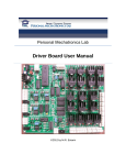
Personal Mechatronics Lab Sensor Board User Manual ©2012 by M.R. Emami Sensor Board User Manual Table of Contents 1.0 Introduction ...................................................................................................................................... 3 1.1 Summary of Features .......................................................................................................................... 3 2.0 Board Modules ........................................................................................................................................ 5 2.1 Temperature Sensor ........................................................................................................................... 5 2.2 Switch Sensors .................................................................................................................................... 8 2.3 Emitter-Phototransistor Sensors ...................................................................................................... 10 2.4 Photodiode Sensor ............................................................................................................................ 12 2.5 Comparator ....................................................................................................................................... 14 2.6 PIR Motion Sensor............................................................................................................................. 16 2.7 Generic Inputs ................................................................................................................................... 19 2.8 Resistive Sensors ............................................................................................................................... 21 2.9 Active Filter ....................................................................................................................................... 23 2.10 Signal Conditioning ......................................................................................................................... 25 2.11 Power .............................................................................................................................................. 29 2.12 PIC and A/D Select .......................................................................................................................... 31 3.0 Firmware ............................................................................................................................................... 34 3.1 Bootloader ........................................................................................................................................ 34 3.2 Main Firmware .................................................................................................................................. 34 4.0 PC Software ........................................................................................................................................... 37 Personal Mechatronics Lab 2 Sensor Board User Manual 1.0 Introduction The functional purpose of the Sensor Board is to act as a transducer and conditioning hub for input signals. Although the board is primarily designed to handle inputs from sensors, it is capable of receiving and conditioning generic inputs from other sources as well, provided that compatibility issues such as logic voltage level are taken into proper consideration. As a transducer, the Sensor Board uses a combination of hardware, firmware, and PC software to enable the user to monitor input signals. These inputs can then be mapped to any of the four outputs to drive external circuits. As a conditioning hub, the board provides voltage comparison and amplification, signal debouncing, low-pass filtering, as well as arithmetic functions including integrating, differentiating, difference, and summing to modify signals according to the user’s needs. The second purpose of the Sensor Board is to be an educational tool for a user seeking to learn about the circuits used for different types of sensors, as well as the conditioning process for turning raw signals into a clean signal that is more useful for processing. In using this board, the user will learn how to apply any of the various sensors and signal conditioning features supported by the board into his or her own projects, and will deal first-hand with the impact of noise on the performance of a sensor, and finally, learn the importance of sensor calibration. These goals are facilitated through the onboard instructions and indicator LED’s, as well as the PC interface and User Manual. 1.1 Summary of Features In order to function properly, the Sensor Board must be powered either through a USB connection to a computer, or with 7.5-17.5V sourced from an AC-DC adapter. Using one of these power sources, the board itself can also be used as a power source capable of providing 5V and 3.3V at small values of current. In terms of its functional components, the Sensor Board has modules specifically designed for the following sensors: One LM335 temperature sensor Up to two SPST or SPDT switches Up to two emitter-phototransistor type sensors One photodiode sensor One PIR sensor (designed for the IRA-E700ST0) Up to two resistive sensors The board also supports the following signal conditioning inputs: One input to a comparator Up to four generic inputs, which can be configured into one of six pre-set combinations of analog and digital settings o Of these four inputs, up to two can be amplified o Of these four inputs, up to two can be debounced o However, amplification and debouncing cannot be applied to the same input signal One input to a low-pass filter that can be configured as either an analog or digital input Personal Mechatronics Lab 3 Sensor Board User Manual One input through a signal conditioning module that provides integration, differentiation, summing, difference, peak detection, or sample and hold for one or two signals depending on the operation used The features contributed by the PIC18F4550 microcontroller include: Analog to digital conversion using either external or internal reference voltage settings (external reference voltage settings range from 0V to 5V) Four software configurable output pins Bootloader for programming firmware Can be configured for I2C communication Can be configured for RS-232 communication USB communication for programming through the bootloader, as well as for enabling communication with the PC application Personal Mechatronics Lab 4 Sensor Board User Manual 2.0 Board Modules 2.1 Temperature Sensor Location on board Figure 1: Physical location of the Temperature Sensor module Personal Mechatronics Lab 5 Sensor Board User Manual Schematic Figure 2: Schematic of the Temperature Sensor module The temperature sensor circuit contains a four-pin input terminal, three of which are configured specifically to match the pin configuration of the LM335 temperature sensor. Pin X10-1 is used as the sensor calibration pin (ADJ), pin X10-2 is used as the output pin (V+), and pin X10-3 is used as the ground pin for the sensor (GND). The fourth pin, X10-4, is connected directly to the input pin of the PIC18F4550 to enable monitoring of the module’s output received by the microcontroller. A DPDT slide switch is provided with the module, and depending on whether it is set on Hot or Cold, the V+ pin of LM335 is connected to the inverting pin of the comparator while the reference voltage is connected to the noninverting pin, or vice versa. Finally, the pulled-up output of the comparator is connected to pin RB6 of the microcontroller, with a buffered LED in parallel to visually display the output state of the module. Functional Overview The LM335 temperature sensor works as a zener diode with a breakdown voltage that varies linearly with temperature: , where and are the reference voltage and temperature (calibrated). By extrapolating the output of the sensor to be 0V at absolute zero, the sensor can be calibrated to express the correct output at any temperature through the following equation: (in mV) = 10 x (in Kelvin). For example: at 25°C = 298°K, Personal Mechatronics Lab 2980mV or 2.98V. 6 Sensor Board User Manual Once calibrated for a given temperature, the sensor will work correctly for all other temperatures. To provide a simple and easy to process output, the senor is implemented in an application circuit that determines if the detected temperature is greater or less than a user selected value. The circuit design used to digitize the output from the sensor is taken directly from the datasheet of the sensor, with some modifications due to a difference in supply voltage. First, the sensor is connected in series with a 2kΩ resistance across 5V and ground, resulting in the voltage at the V+ pin being the breakdown voltage of the LM335. By connecting this voltage to a LM339 comparator, output can be generated when the breakdown voltage exceeds or goes below the reference voltage. This would correspond to the detected temperature exceeding the value determined by the reference voltage in the Hot mode, and going below it in the Cold mode. In order to calculate the temperature value that corresponds to a set reference voltage, it is first necessary to calibrate the sensor as was outlined previously. For this, the user simply has to turn the trimmer labelled “Calibration” until the output voltage matches the expected value for the ambient temperature. As an example, the datasheet recommends the output be calibrated at 2.982V for an ambient temperature of 25°C. The output generated by the LM339 is connected to pin RB6 of the microcontroller, and is recognized as a digital input. Furthermore, the user may probe and access the output directly through monitoring the pin labelled “RB6” that is provided in the module. NOTE: The trimmers may be out of range. In case of any problems with operating the module, it is highly recommended that the user first tries sufficiently turning them in both directions. Personal Mechatronics Lab 7 Sensor Board User Manual 2.2 Switch Sensors Location on board Figure 3: Physical location of the Switch Sensors module Personal Mechatronics Lab 8 Sensor Board User Manual Schematic <- To debouncer IC The switch sensor module provides input terminals for up to two switch sensors that can be used simultaneously. For each sensor, a four-pin terminal provides pins for input, ground, 5V, and for monitoring of the output to the microcontroller. The module supports using a switch to generate either high or low output through the use of the pull-up and pulldown resistances that can be selected via a SPDT switch for each sensor. Lastly, the output of the switch is passed through the MC14490 signal debouncer chip to remove spikes inherent in mechanical switching actions. Figure 4: Schematic of the Switch Sensors module Functional Overview The switch sensor module has a simple and straightforward circuit. First, the onboard SPDT switch is used by the user to determine what state the output should be in when the switch is open. This state can be high (output pulled up to 5V), or low (output pulled down to ground). Once the switch is closed, the open state is overwritten by switch. For example, if the open state is set to high and the leads of an SPST switch are connected to IN and GND, closing the switch will result in the low output. In addition to SPST switches, a SPDT switch can also be used by connecting the throws of the switch to 5V and GND, and the common pin to the input. Due to the mechanical motion required to open and close switches, the signal will bounce during the transition from high to low (or vice versa). In order to eliminate this, the output is debounced using the MC14490 integrated circuit before being routed to the input pins of the microcontroller. Lastly, the user is able to use the pins labelled “RC0” and “RD7” to monitor the output received by the microcontroller, and use it in other circuits or modules. Personal Mechatronics Lab 9 Sensor Board User Manual 2.3 Emitter-Phototransistor Sensors Location on board Figure 5: Physical location of the Emitter-phototransistor module Personal Mechatronics Lab 10 Sensor Board User Manual Schematic Figure 6: Schematic of the Emitter-phototransistor module This module provides a five-pin terminal that supports any combination of emitter and phototransistor. The terminal provides connections for the collector and emitter pins of a phototransistor (X9-3 and X94), as well as connections for the leads of an emitter (X9-1 and X9-2). The fifth pin is connected directly to the input of the microcontroller. The output of the sensor is digitized through the use of an LM339 comparator before being sent to a digital input pin of the microcontroller. In addition, a DPDT switch is used to swap the connections of the sensor output and reference voltage to the input pins of the comparator. A socket is also provided, pins 2 and 3 of which should be used to connect external resistor. Functional Overview The emitter-phototransistor module provides a simple and easy to use circuit through its digital output, and its ability to provide dark or light activated output. The five-pin terminal block provides the user with all of the connections necessary to use a sensor and emitter combination. Furthermore, the DPDT switch provides a straightforward means to select between two ways to generate output. When the switch is set for dark activated output, the raw output of the sensor is connected to the non-inverting pin of the LM339, while the reference voltage is connected to the inverting pin. When no light is received by the sensor, the voltage at the emitter will be 5V, which will impose 5V at the non-inverting pin of the comparator, resulting in high output. Alternatively, when the switch is set for light activated output, the sensor output is connected to the inverting pin of the comparator, while the reference voltage is connected to the non-inverting pin. This means that when the sensor is saturated by light, the voltage at the emitter will drop to ground, therefore causing the voltage at the inverting input of the comparator to be 0V. In this situation, the comparator will output a high signal because the voltage at the non-inverting input will be greater than the voltage at the inverting input. Using the trimmers and connecting an appropriate resistor for the emitter on pins 2 and 3 of the socket calibrate the module. NOTE: The trimmers may be out of range. In case of any problems with operating the module, it is highly recommended that the user first tries sufficiently turning them in both directions. Personal Mechatronics Lab 11 Sensor Board User Manual 2.4 Photodiode Sensor Location on board Figure 7: Physical location of the Photodiode module Personal Mechatronics Lab 12 Sensor Board User Manual Schematic The circuit for the photodiode module is a simple amplification circuit. Using an LM358 amplifier chip and variable feedback resistance, the voltage generated by the photodiode is amplified before being passed to the microcontroller as an analog input. A jumper located in the module allows the user to send the output of the amplifier to the comparator module to digitize the output. Figure 8: Schematic of the Photodiode module Functional Overview There are two ways to operate a photodiode sensor, photovoltaic and photoconductive. In this application, the photodiode is used in photovoltaic mode. By connecting the cathode to the amplifier, any voltage change generated by the amount of light received by the sensor is directly input to the amplifier, resulting in useful output that is received by the microcontroller as an analog input. In order to support a wide range of sensors and applications, a variable resistance is used in the feedback loop to make the gain adjustable. Furthermore, if the user wishes to generate a digital output from the photodiode, shorting the pins of JP4 with a jumper will connect the output of the amplifier to the comparator module, where the output can be digitized via comparison with a reference voltage. In the mean-time, the AN4 pin of the terminal can be used to monitor the analog output of the module. NOTE: The trimmer may be out of range. In case of any problems with operating the module, it is highly recommended that the user first tries sufficiently turning it in both directions. Personal Mechatronics Lab 13 Sensor Board User Manual 2.5 Comparator Location on board Figure 9: Physical location of the Comparator module Personal Mechatronics Lab 14 Sensor Board User Manual Schematic Figure 10: Schematic of Comparator module The comparator module is designed to receive any input signal, and use the specified reference voltage to turn the input into high or low digital output for the microcontroller. To accomplish this, the module provides an input terminal, as well as a common ground pin. The input is connect to the non-inverting pin of a LM339 comparator, and is also pulled to ground to prevent the input from floating when not connected to a signal source. Since the LM339 receives a supply of 5V, input signals can only be received within the range of 0-5V. The open drain output of the comparator is pulled up to 5V through a 10kΩ resistor in order to provide the correct output. The third terminal pin is connected to the output of the comparator for monitoring of the input received by the microcontroller. Functional Overview The comparator module is simple to use, and requires minimal interaction with the user to generate the desired output. In order to use the module, the user must first connect the input signal to the IN pin, and connect the ground of the signal source to the GND pin. Next, the user must set the reference voltage on the inverting pin using the on board potentiometer. By turning the knob clockwise, the reference voltage can be increased up to 5V. Turning counter clockwise will decrease the reference voltage to a minimum of 0V. The LM339 gate will output logic high if the non-inverting input voltage exceeds the inverting input voltage (reference voltage), and will output logic low if the reverse is true. This output is received by the microcontroller on pin RD0. NOTE: The trimmer may be out of range. In case of any problems with operating the module, it is highly recommended that the user first tries sufficiently turning it in both directions. Personal Mechatronics Lab 15 Sensor Board User Manual 2.6 PIR Motion Sensor Location on board Figure 11: Physical location of the PIR Motion Sensor module Personal Mechatronics Lab 16 Sensor Board User Manual Schematic Figure 12: Schematic of the PIR Motion Sensor module This module contains a large number of components in order to support the many functions and configurations required by the LS6511 chip. Many passive components are used for setting parameters for how the chip should function. The function of some of these passive components is described in the functional overview. For the sake of brevity and to avoid redundancy, the reader is encouraged to read the datasheet for the LS6511 for a more detailed breakdown of the application circuit used. Functional Overview The PIR sensor module is the most complex of all the sensors, requiring a significant amount of user knowledge and setup time in order to function properly. This module was designed to be used with the IRA-E700ST0. Once this sensor is plugged into the 5V, IN and a GND terminal, its input is connected to the LS6511 PIR controller chip. This chip uses a combination of integrated amplifiers, comparators and timer circuits to turn the oscillating input of the PIR sensor into a single digital signal. Since the chip requires that many of the supporting passive components be included externally, the user has control over the sensitivity of the sensor input, the gain of the amplification stages, as well as timing characteristics for the output. The chip is also capable of operating in three different modes: single pulse, concurrent pulses, and dual pulses. In single pulse mode, the chip will react to one high/low pulse from the sensor and generate an output. In concurrent pulse mode, the chip will only react to a high and low pulse concurrently, requiring a much more extensive motion to generate output. In dual pulse mode, the chip will recognize any combination (high or low) of two pulses to generate output. To reduce some of the work required to setup the module, the user only has to set five parameters: 1) The first parameter the user must set is the resistance for the RC timer circuit of the integrated comparator. The resistor should be connected to pins 2 and 3 of the socket labeled “Dig. Filter”. Personal Mechatronics Lab 17 Sensor Board User Manual 2) 3) 4) 5) This timer acts as a filter so that the motion must be present for a set amount of time (set by the RC) before it is recognized as output. Second, the user must set the duration timer RC to determine how long a single output pulse will last. This resistor should be connected to pins 2 and 3 of the socket labeled “Dur. Time”. Third, the user can use the trimmer labeled “Sensitivity” along with the next point. Fourth, the user can adjust the variable resistance labeled “Stage 2 Gain” to control the sensitivity of the sensor. Decreasing both resistances will tune the sensor for detection of larger objects and motions, while increasing sensitivity will enable detection of motion for smaller objects, such as a hand. Finally, the user must select which mode (SP, CP, DP) to operate the chip in. If CP or DP is selected, the user must set the resistance for an RC network that determines the wait time for two pulses to be received. This resistor should be connected to pins 2 and 3 of socket labeled “CP/DP Timer”. Using the datasheet values as a starting point, the user must continuously adjust these parameters until the module provides the desired output. According to the following section of the datasheet, the recommended typical value for the resistors is 2.2 MΩ. NOTE: The trimmers may be out of range. In case of any problems with operating the module, it is highly recommended that the user first tries sufficiently turning them in both directions. Figure 13: Schematic of a typical application circuit for the chip Personal Mechatronics Lab 18 Sensor Board User Manual 2.7 Generic Inputs Location on board Figure 14: Physical Location of the Generic Inputs module Personal Mechatronics Lab 19 Sensor Board User Manual Schematic The generic inputs module contains two types of inputs. The included schematic details the application circuit of the two amplifiable inputs. Using a non-inverting configuration, the amplifier circuit uses a potentiometer to implement voltage division of the output voltage to the inverting input of the operational amplifier, setting the gain for the signal. By shorting the pins of JP7, the user is able to remove this gain so that the signal passes unaltered to the microcontroller. The other two inputs in the module may be connected to the MC14490 signal debouncing chip in the switch sensor module, providing the same signal conditioning used for the switch sensor inputs. Figure 15: Schematic of the Generic Inputs module Functional Overview To use the generic inputs module, the user must first decide if amplification is desired. If that is the case, the user must use either the “IN1” pin or the “IN2” pin of the module. Then, using the trimmer for the associated amplifier, the user must set the gain by turning the trimmer knob clockwise (increases gain), or counter clockwise (decreases gain). However, if no gain is desired, the user can simply use a jumper to short out the feedback resistance, setting the gain of the amplifier to 1 (no amplification). Alternatively, the user can pass unamplified signals to the microcontroller through the two debouncable inputs “IN3”and “IN4”. If the user wishes to apply dobouncing to an input signal, all that is required is to change the position of the jumper to short the pins labeled “IN3”/”IN4” and “Debounce.” The ease of use and configurability of the generic inputs provides a great deal of flexibility for the user. Furthermore, the four input pins used in the generic inputs module can be configured to be analog or digital inputs, providing additional customization options for the user. In order to do the analog/digital configuration, the user should use the 3 DIP switches in the PIC and A/D Select module, along with the provided table. NOTE: The trimmers may be out of range. In case of any problems with operating the module, it is highly recommended that the user first tries sufficiently turning them in both directions. NOTE: The output of the amplifier does not exceed 3.65 V, due to consumption of other modules. Personal Mechatronics Lab 20 Sensor Board User Manual 2.8 Resistive Sensors Location on board Figure 16: Physical Location of the Resistive Sensors module Personal Mechatronics Lab 21 Sensor Board User Manual Schematic Figure 17: Schematic of the Resistive Sensors module The resistive sensor module provides circuits for up to two resistive sensors that can be used simultaneously. For one of the inputs, a DPDT switch is provided to implement light or dark activated output for photoresistors. The application circuits for this module are simply voltage divider circuits with sockets that enable the user to pick the second resistive component based on the properties of the sensor being used. The outputs of this module are connected to pins RA0 and RA1 of the microcontroller as analog inputs. Functional Overview Resistive sensors are used as part of a voltage divider network in order to generate output. Therefore, the output is governed by the equation: if the sensor is connected to ground, and if the sensor is connected to the supply voltage. In order to use the resistive sensor module, the user must first know the resistive properties of the sensor being used, and then select an appropriate fixed resistance to create a voltage divider with a wide range of outputs. This resistor, which is symbolized by R in the above formulation, should be placed on pins 1 and 2 of the socket. Furthermore, when using a photoresistor, the user has the option of using the sensor in light or dark activated modes by using a DPDT switch to swap the connections of the sensor and the fixed resistance. Personal Mechatronics Lab 22 Sensor Board User Manual 2.9 Active Filter Location on board Figure 18: Physical Location of the Active Filter module Personal Mechatronics Lab 23 Sensor Board User Manual Schematic The active filter module contains a 3-pin terminal for the input signal, common ground connection, and output monitoring. The input pin is connected to a MAX7426 low pass filter chip. The chip contains an offset adjustment through a combination of fixed and variable resistances, as well as an externally controlled cut-off frequency provided by a 555 timer circuit. The output frequency of the timer is controlled by the user via a potentiometer. The output of the module is connected to pin RB3 as an input that can be configured to be either analog or digital. Figure 19: Schematic of the Active Filter module Functional Overview In most cases, the output of a sensor is a noisy signal containing numerous fluctuations at various frequencies. Because this noise issue may not always be addressed directly by eliminating the sources of the noise, it is often more practical to remove this noise with signal processing. When the signal is either analog or digital DC, the noise present in the signal can be easily removed by attenuating the high frequency components. To accomplish this, a low pass filter such as the MAX7426 is used. In order to use this module, the user needs only adjust the offset and cut-off frequency trimmers in order to apply low pass filtering to the input signal. Adjusting the offset voltage can be used to get rid of internal bias in the chip, and to match the output voltage to the input voltage level. Increasing or decreasing the cut-off frequency provides the user with the flexibility of controlling how the output signal will look like based on the amount of noise that is attenuated. Since the input pin on the microcontroller can be configured as analog or digital, this module can be used to apply filter to any input signal in the range of 0 - 5V. NOTE: The trimmers may be out of range. In case of any problems with operating the module, it is highly recommended that the user first tries sufficiently turning them in both directions. Personal Mechatronics Lab 24 Sensor Board User Manual 2.10 Signal Conditioning Location on board Figure 20: Physical Location of the Signal Conditioning module Personal Mechatronics Lab 25 Sensor Board User Manual Schematic Figure 21: Schematic of the Signal Conditioning module Due to the highly modular nature of the signal conditioning module, very few components are actually included on board. For the summation, difference, integration, and differentiation operations, a single amplifier gate is used to handle up to two inputs. For peak detection and sample and hold operations, two amplifier gates are included, one of which has some of its connections integrated on board. Sockets are used to allow the user to connect various passive components and wires to create circuits corresponding to the available operations. Since the module only has one output, a jumper is used to select which of the two sets of circuits will send its output to the microcontroller. Functional Overview The signal conditioning module is designed to enable the user to apply various operations to an input signal. This input can include up to two analog signals, enabling the user to perform the following operations: 1. 2. 3. 4. 5. 6. Add two signals Take the difference of two signals Integrate an input signal Differentiate an input signal Peak detection for an input signal Sample and hold for an input signal Personal Mechatronics Lab 26 Sensor Board User Manual The first four operations are accomplished by connecting passive components to the sockets labelled “Circuit 2,” while the remaining two operations are assembled using the “Circuit 1” sockets. Using these sockets, the following table demonstrates the circuits that can be created and the resulting input-output relations: Operation Non-inverting Summing amplifier ( )( Circuit ) Difference amplifier ( ) Non-inverting Integrator ∫ Personal Mechatronics Lab 27 Sensor Board User Manual Differentiator Sample and hold - The output of the amplifier will retain the value of Vin prior to the switch being opened - Add a 10kΩ resistance between the capacitor and the noninverting input. Peak detector - Output will hold the highest value of the input signal. Table 1: Voltage relationship and schematic for each conditioning operation NOTE: In order to avoid reverse current flow, high resistance values in the range of mega-ohms are recommended for use before the input pins of the amplifier. For instance, for the summing circuit, resistances of 1.5 MΩ are recommended for the inputs. Using small resistance may result in large errors in conditioning due to high voltage drops. Personal Mechatronics Lab 28 Sensor Board User Manual 2.11 Power Location on board Figure 22: Physical Location of the Power module Personal Mechatronics Lab 29 Sensor Board User Manual Schematic Figure 23: Schematic of the Power module The power module integrates all of the components used to deliver logic level voltage to the board. For DC power, a rectifier bridge, a 1.25A fuse, a 5V regulator, and a ferrite are used to accept a range of 177V of DC input to power the board. For USB power, only a ferrite is needed. Lastly, there is a power output terminal that provides buffered 5V, regulated 3.3V and GND connections for powering small external circuits. Functional Overview This module provides two ways to power the Sensor Board: DC, and USB. When using the DC input, the user is required to connect an AC-DC adapter into the DC IN jack. In order to prevent damage to the board through reverse polarity, a diode bridge is implemented before the power switch. This switch controls both DC and USB power. For DC power, a fuse is implemented to protect the integrated circuits of the board from currents exceeding 1.25A in case of any failure causing a short circuit. In order to ensure the DC input voltage can be used by the board, a 5V regulator is used to maintain the supply voltage for all the components of the board at 5V. This also means that the DC input supply voltage can range safely from 7V to 17V, with the recommended voltage being 12V. In order to further stabilize the input power and to eliminate noise, a total of four capacitors are used across the regulator and ground. The ferrite bead provides additional filtering before the power is finally routed to the rest of the board. When USB power is used, only a ferrite bead is employed for filtering because the 5V power input from the USB port of a computer is already conditioned for use by the board. The last feature of the power module is the PWR OUT terminal block. This terminal provides a buffered 5V output, a 3.3V regulated output, and a ground pin for powering external circuits. Due to the buffer at the 5V output, and the current limitations of the 3.3V regulator, drawing more than 25mA from the 5V output or 700mA from the 3.3V output is not recommended. Personal Mechatronics Lab 30 Sensor Board User Manual 2.12 PIC and A/D Select Location on board Figure 24: Physical Location of the PIC and A/D Select module Personal Mechatronics Lab 31 Sensor Board User Manual Schematic Figure 25: Schematic of the PIC and A/D Select module The schematic includes almost all of the features that are available in this module. The four buffer gates, two of which are in the bottom-left part of the schematic, are used for the outputs that are provided by the board. These outputs can be user configured through either software or firmware to respond to any combination of inputs received by the microcontroller. In the top-left of the schematic, the two potentiometers are used to provide the +/- reference voltages for analog to digital conversion. Note that because of their configuration, both reference voltages can only take a value between 0V and 5V. In the top-centre there are two switches used for microcontroller’s reset and bootloader functions. The three DIP switches in the top-right of the schematic are used for setting the configuration of the five customizable inputs as analog or digital based on the provided table. Lastly, terminals for I2C and circuits for RS-232 communication are included in the middle-right and bottom-right region, respectively. All of these features are controlled by the PIC18F4550 microcontroller in the centre of the schematic. Functional Overview The PIC module centralizes all of features of the board that affect the functionality of multiple modules, and more specifically, how they interact with the microcontroller. The sensor board has four output pins that can be controlled through either software or firmware. As part of the default code, these outputs conform to the following configuration: Output pin RC1 will follow the output of phototransistor 1 OR phototransistor 2 Output pin RC2 will follow the output of switch 1 OR switch 2 Output pin RD5 will follow the output of the PIR sensor Output pin RD6 will follow the output of the comparator OR temperature sensor Personal Mechatronics Lab 32 Sensor Board User Manual Using the PC software, the user can create their own mapping for these outputs, which will remain in effect for as long as the board is connected to the computer. Persistent changes to the output configuration require modification of the firmware, either by directly editing the default code or by creating user written code. The I2C and RS-232 terminals provided allow the board to communicate with other devices using these protocols; however, this requires the user to implement their own code as there is currently no sample code provided for initializing and using these features. The last major functional feature in the PIC module is the analog/digital configuration switches for the five configurable inputs. In order to select a configuration, the user can simply read the table included on the board which instructs which switch settings will enable the various available configurations. In order for the analog to digital conversion feature of microcontroller to provide usable output, the user must first set the +/reference voltages. It should be noted that this setting will apply to both the analog sensor inputs, as well as the configurable inputs that are set by the user to be analog. Personal Mechatronics Lab 33 Sensor Board User Manual 3.0 Firmware The firmware for the Sensor Board comprises of two separate elements; the bootloader and the default code. Both are built from Microchip’s open-source USB libraries. The board is configured as an HID device in order to simplify detection, and for consistency with the firmware for the other boards. 3.1 Bootloader The bootloader is implemented to allow the user to burn new code into the microcontroller without the need of an external programmer. This is useful for both updating the firmware and enabling user written code. However, the Sensor Board currently does not support appending user code into the existing firmware, and consequently any customization firmware would require access to the source code of the default firmware. In order to use the bootloader feature of the board to burn new firmware into the microcontroller, the user must follow several steps, namely: 1. Plug the board into a computer that has the HID bootloader software. 2. After starting the software application, the user must press the “Reset” button while holding the “Bootloader” button on the board. Powering on the board while holding the “Bootloader” button accomplishes the same thing. 3. At this point, the software should detect the board, enabling the user to import and program a hex file into the microcontroller. 4. Once the programming operation is complete, simply disconnect the board from the computer and press the “Reset” button once more. The microcontroller will then begin to execute the newly programmed code. NOTE: The Sensor Board software application itself has a built-in bootloader feature. 3.2 Main Firmware Since the majority of the processing for each input is done using external circuits, the microcontroller does not require a large amount of code in order to make use of the inputs. This simplifies the firmware implementation to control the following tasks: 1. 2. 3. 4. Reading the input pins, including analog to digital conversion for analog inputs Reading information sent from the PC via USB communication Generating output signals based on sensor inputs and/or instructions set by the PC software Sending the input and output data to the PC software via USB Default output configuration: Output pin RC1 will follow the output of phototransistor 1 OR phototransistor 2 Output pin RC2 will follow the output of switch 1 OR switch 2 Output pin RD5 will follow the output of the PIR sensor Output pin RD6 will follow the output of the comparator OR temperature sensor Personal Mechatronics Lab 34 Sensor Board User Manual NOTE: The above “OR”s are logical ORs. In order for the user to program a new PIC18F4550 with the default code for the sensor board, the following procedure is followed: 1) The PIC is placed in the 40 pin socket of the Microcontroller board (DevBugger). 2) The DevBugger is turned ON and set on PRG mode. Then, the file “HID Bootloader PIC18 Non J.hex” is written on the PIC. This is the bootloader hex file. 3) The PIC is removed and set in place on the Sensor board. The board is connected to the computer, and then turned ON, while the Bootloader switch is held. 4) The Sensor Board PC application is launched. Then, the Bootloader option is clicked. 5) If the preceding steps have been followed correctly, the feature will recognize the Sensor board in Bootloader mode. The file “Sensor Board Default Code.hex” is then opened and programmed on the PIC. 6) After resetting the Board (either by turning OFF and ON again or using the reset switch), the software should be closed and launched again. Upon re-launching, the Sensor board should start collaborating with the PC application. Personal Mechatronics Lab 35 Sensor Board User Manual The following table contains the complete pin assignment: Port A B C D E Pin RA0 RA1 RA2 RA3 RA4 RA5 RA6 RA7 RB0 RB1 RB2 RB3 RB4 RB5 RB6 RB7 RC0 RC1 RC2 RC3 RC4 RC5 RC6 RC7 RD0 RD1 RD2 RD3 RD4 RD5 RD6 RD7 RE0 RE1 RE2 A/D Port AN0 AN1 AN2 AN3 AN4 I/O Input Input Input Input Input Input Pin Usage Analog input A/D conversion reference voltage A/D Selector Analog input Module Resistive Sensors PIC Module Photodiode Timer(Crystal) AN12 AN10 AN8 AN9 AN11 DD+ TX RX AN5 AN6 AN7 Input Input Input Input Input Input Input Input Input Output Output Output Output Output Input Output In In In In In Out Out In In In In PIC Module 2 IC Analog/Digital input Analog/Digital input Analog/Digital input A/D selector Digital Input Bootloader Digital input Generic Inputs (Debounce 1) Active Filter Generic Inputs (Debounce 2) PIC Module Temp Sensor PIC Module Switch Sensor Digital Output Output Module Power (USB) PIC Module USB Communication Power Module RS-232 PIC Module Comparator Digital Input Phototransistor A/D selector PIR Motion Detector PIC Module Digital Output Output Module Digital Input Switch Sensor Signal Conditioning Analog/Digital Input Generic Inputs (Amplifiers) Table 2: Complete pin assignment of the PIC18F4550 Personal Mechatronics Lab 36 Sensor Board User Manual 4.0 PC Software The primary objective of the PC interface is to make the board easier to use for testing various inputs and outputs. Using the USB communication capabilities of the PIC18F4550 microcontroller offers the user the choice of controlling the various features of the Sensor Board through a personal computer. Using the PC interface, the user is able to monitor the state of all sixteen inputs in one easy to read display. Furthermore, up to five different signals can be graphed at the same time, allowing further investigation into the behaviour of the various modules on the board. Using this information, the user can configure each of the four available output pins to respond to a specific logic operation on one or more input signals. Figure 26: Main window of the PC software application Personal Mechatronics Lab 37 Sensor Board User Manual The preceding image displays how the input signals are monitored in the application, as well as the available graphs. The configurable signals can be configured as either analog or digital using the 3 switches on the board, and based on the provided table. NOTE: The A/D conversion uses the user-selected voltages as its + and – reference voltage. These voltages can be changed by turning the trimmers. In case the PC application seems to be unable to read the configurable signals properly as analog (i.e. always shows 255 or 0), it is highly suggested that the user first tries turning the V+ clockwise and the V- counter-clockwise as much as possible (hence increasing the reference voltage range). The following image is an overview of the configuration page. By adding inputs, removing inputs, and configuring the logic operation between each input from the sensors, the user is able to configure what each of the four outputs of the Sensor board corresponds to (Which are RC1, RC2, RD5, and RD6). In addition, for analog sensors, the user is allowed to choose a reference value between 0 and 255. Figure 27: The Configuration window of the PC software application Personal Mechatronics Lab 38 Sensor Board User Manual Also, for digital outputs, the user can select whether to show high when the input signal is high, or show low in such cases. On the other hand, for analog signals, the user should enter a threshold value, and choose whether to show high when the input is greater than the threshold, or when it is less. Finally, the image below shows the bootloader feature of the software. As explained in Section 4.1, HID Bootloader Software is required to initially program the PIC. This software has been built-in the Sensor Board PC application, and can be used for the purpose of programming new firmware on the PIC. Figure 28: The Bootloader feature of the PC software application Personal Mechatronics Lab 39