1
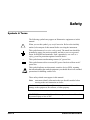
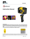
User Guide EpiSensor Force Balance Accelerometer Model FBA ES-U2 Document 301929 Revision B June 2013 Trademarks This manual copyright © Kinemetrics, Inc., 2013. All rights reserved. Kinemetrics products are covered by U.S. and foreign patents, issued and pending. Printed in U.S.A. The trademarks used throughout this manual, registered or not, are: Kinemetrics, Quanterra , Rock, Basalt, Granite, RockHound, Q330, Q330 HR, Q330S, Q330S+, EpiSensor, SBEPI, HypoSensor, Altus, Etna, K2, Mt. Whitney, QuickTalk, QuickLook. Kinemetrics, Inc., 222 Vista Avenue, Pasadena, CA 91107 USA Phone: (626) 795-2220 Fax: (626) 795-0868 E-mail: [email protected] Technical Support: [email protected] Website: www.kinemetrics.com Website: www.kinemetrics.com Kinemetrics SA, ZI Le Tresi 6B, CH-1028 Preverenges, Switzerland Phone: 21.803.2829 Fax: 21.803.2895 E-mail: [email protected] Table of Content Safety ...................................................................... 1 Symbols & Terms .......................................................................................... 1 Specific Precautions ....................................................................................... 2 1. Introduction ........................................................ 1 The EpiSensor ES-U2 .................................................................................... 1 Inspecting the EpiSensor................................................................................ 2 2. Installation Basics .............................................. 5 Requirements for Installation ......................................................................... 5 Required Tools ....................................................................................... 5 Required Supplies .................................................................................. 6 Required Equipment .............................................................................. 6 Mounting & Orienting ................................................................................... 7 Connecting to the Data Logger .................................................................... 11 Grounding the EpiSensor ............................................................................. 12 Safety First ........................................................................................... 12 EMI/RFI ............................................................................................... 13 Low Noise Operation ........................................................................... 14 Powering the EpiSensor ............................................................................... 14 Zero-Adjusting the EpiSensor...................................................................... 15 Methods of Measuring the DC Offset .................................................. 15 Performing the Zero Adjustment on the Standard Zero Adjustment Unit ...................................................................................................... 15 Performing the Zero Adjustment on the Factory Set Zero Adjustment Units ..................................................................................................... 16 Note: Why a Mechanical Zero Adjust ................................................ 17 Note on Full-Scale Range .................................................................... 18 3. Operating Basics .............................................. 19 Signal Polarity.............................................................................................. 20 Required Power ............................................................................................ 20 Performing a Functional Test with a Rock Digitizer ................................... 20 Sensor Response Test .................................................................................. 21 EpiSensor Configuration .............................................................................. 21 Opening the EpiSensor Case ................................................................ 22 Jumper Selectable Options ........................................................................... 22 Setting the Full-Scale Range ........................................................................ 22 EPISENSOR ES-U2 USER GUIDE SAFETY 1 Power Supply Options ......................................................................... 25 Calibration Coil............................................................................................ 25 Closing the EpiSensor Case ................................................................. 26 4. Maintenance ..................................................... 27 Recommended Maintenance ........................................................................ 27 Adjust the Accelerometer .................................................................... 27 Complete a Functional Test ................................................................. 27 Calibration............................................................................................ 27 Desiccant Replacement ........................................................................ 28 Troubleshooting and Repair................................................................. 28 5. Reference.......................................................... 29 Theory of Operation ..................................................................................... 29 Working Principle ................................................................................ 30 Features ................................................................................................ 31 Pole Zero Representation of the EpiSensor ................................................ 31 Polarity Conventions .................................................................................... 34 6. Advanced Installations ..................................... 35 Using EpiSensors with Rock & Q330 Instruments..................................... 35 The Granite and Basalt Digitizers ........................................................ 35 Q330 Digitizers .................................................................................... 36 Long Cables ................................................................................................. 36 User-Supplied Cable ............................................................................ 37 Grounding ............................................................................................ 38 Use with Non-Kinemetrics Data Loggers ................................................... 39 Power Supply ....................................................................................... 39 Output Voltage ..................................................................................... 40 Calibration Sequence ........................................................................... 40 Ground Loop Prevention...................................................................... 41 EpiSensor ES-U2 Specifications.................................................................. 42 Figures Figure 1: EpiSensor ES-U2 ........................................................................... 3 Figure 2: Episensor Mounting Dimensions ................................................... 8 Figure 3: Episensor ES-U2 Hole Mounting Pattern ...................................... 9 Figure 4: Drilling Episensor Mounting Holes ............................................. 10 Figure 5: Factory Set Zero Adjustment Tool .............................................. 16 Figure 8: Jumper settings for sensor g-level ................................................ 23 SAFETY 2 EPISENSOR ES-U2 USER GUIDE Figure 9: Jumper settings for sensor output voltage .................................... 24 Figure 10: Jumper settings for single-ended or differential output.............. 24 Figure 11: Jumper settings for 2g, ±5V, differential configuration ............. 25 Figure 13: Amplitude, Phase, And Step Response ...................................... 33 Tables Table 1: Option Part Numbers ....................................................................... 2 Table 2: ES-U2 Connector ........................................................................... 11 Table 3: Reasonable Zero Offset Voltages .................................................. 16 Table 5: Typical Cable Resistance Calculation ........................................... 37 Table 6: Maximium Cable Length Calculation ........................................... 37 Table 7: ES-U2 Current Requirements ........................................................ 40 Table 1: Option Part Numbers ....................................................................... 2 Table 2: ES-U2 Connector ........................................................................... 11 Table 3: Reasonable Zero Offset Voltages .................................................. 16 Table 5: Typical Cable Resistance Calculation ........................................... 37 Table 6: Maximium Cable Length Calculation ........................................... 37 Table 7: ES-U2 Current Requirements ........................................................ 40 EPISENSOR ES-U2 USER GUIDE SAFETY 3 Safety Symbols & Terms The following symbols may appear on Kinemetrics equipment or in this manual. ! When you see this symbol, pay careful attention. Refer to the similarly marked, relevant part of this manual before servicing the instrument. This symbol means a low-noise earth ground. The noted item should be grounded to ensure low-noise operation, and also to serve as a ground return for EMI/RFI and transients. Such a ground does not work as a safety ground for protection against electrical shock! ~ This symbol means an alternating current (AC) power line. This symbol means a direct current (DC) power line derived from an AC power line. This symbol indicates an electrostatic sensitive device (ESD), meaning that when handling the marked equipment you should observe all standard precautions for handling such devices. These safety-related terms appear in this manual: Note: statements identify information that you should consider before moving to the next instruction or choice. Caution statements identify conditions or practices that could result in damage to the equipment, the software, or other property. WARNING! statements identify conditions or practices that could result in personal injury or loss of life. SAFETY 4 EPISENSOR ES-U2 USER GUIDE Specific Precautions Follow the precautions below to ensure your personal safety and prevent damage to the EpiSensor. POWER SOURCE The EpiSensor must be supplied with power either from a recorder or from a customer-supplied ± 12V or ± 15V power supply (or a + 12V supply for the single-supply option). If you plan to power the EpiSensor from a recorder, connect the recorder to a power supply/charger supplied by Kinemetrics, as described in each recorder's user manual. To supply power directly to the EpiSensor, you need a low-noise, regulated ± 12V or ± 15V power supply (or a + 12V supply for the singlesupply option) that is safely grounded and meets all applicable local regulations. The EpiSensor will be damaged if the power is connected with the wrong polarity. USER-SUPPLIED POWER/CHARGING SYSTEM If you supply your own power/charging system, be sure that the system provides the correct voltage and current required by the EpiSensor under all operating conditions. You are responsible for the safety of your charging system. If you get power from the mains supply, be sure you have supplied adequate grounding for all the equipment. If you supply your own batteries, follow the manufacturer’s safety recommendations. SENSOR GROUNDING AND CABLING ! In some cases the EpiSensor will be a long distance from the recorder. In these installations it is possible, due either to faulty AC wiring or extremely high earth-return currents, for a high potential difference to exist between the grounds at the two locations. When the cable is grounded at one end a potentially lethal voltage can exist between the other end of the cable and ground. Consider this danger during installation and get help from a qualified electrician if this danger exists. DO NOT OPERATE IN EXPLOSIVE ATMOSPHERE The EpiSensor provides no explosive protection from static discharges or arcing components. Do not operate the equipment in an atmosphere where explosive gases are present. EPISENSOR ES-U2 USER GUIDE SAFETY 5 DOCUMENT 301929, REVISION B 1. Introduction This document is the User’s Guide to EpiSensor Model FBA ES-U2, a single-axis acceleration sensor. Kinemetrics also produces a triaxial EpiSensor, the FBA ES-T, the FBA ES-SB (Shallow Borehole), and the FBA ES-DH (HypoSensor) triaxial borehole package. Kinemetrics’ strong motion Rock accelerographs feature a triaxial EpiSensor deck. This manual applies only to EpiSensor Model ES-U2. For the sake of brevity, the instrument is referred to simply as the EpiSensor. Kinemetrics is committed to ensuring a successful installation. For assistance with planning, installation, operation or maintenance, contact Kinemetrics at the locations listed in the front of this manual. Kinemetrics also has an extensive Services Group that can install, maintain, and analyze the data from your EpiSensor. This chapter provides an overview of the EpiSensor and inspection instructions. The EpiSensor ES-U2 The EpiSensor is a uniaxial accelerometer optimized for earthquake recording applications. Inside the waterproof, anodized-aluminum housing is one EpiSensor force balance accelerometer module. The EpiSensor has user-selectable full-scale recording ranges of ±4g, ±2g, ±1g, ±1/2g or ±1/4g. Its bandwidth of DC to 200 Hz is a significant improvement over earlier generations of sensors. The output voltage levels are user-selectable at either ±2.5V or ±10V single-ended, or ±5V or ± 20V differential. The EpiSensor is normally powered with a ±12V or ±15V external DC power source. It is optionally available with a single +12V isolated supply option. EPISENSOR ES-U2 USER GUIDE 1 DOCUMENT 301929, REVISION B Full specifications for the unit can be found in Chapter 6. The part numbers of the four available options are shown in the Table 1 below: Table 1: Option Part Numbers KMI Part Number Description 110260-08-PL Dual Supply (+/-12V) Standard Zero Adjust 110240-08-PL Dual Supply (+/-12V) Factory Locked Zero Adjust 110260-18-PL Single Supply (+12V) Standard Zero Adjust 110240-18-PL Single Supply (+12V) Factory Locked Zero Adjust Inspecting the EpiSensor Carefully remove the EpiSensor from its shipping container. Note: If you expect to ship the EpiSensor again, save the shipping container and packing material. Although Kinemetrics takes every precaution in packing its systems, shipping damage can still occur. If you find a problem, note the condition of the shipping container. Then contact the freight forwarder and Kinemetrics as soon as possible. Please contact Kinemetrics before returning a damaged unit. Examine the EpiSensor. The case should appear securely sealed, showing no sign of dents or scratches. Caution: Damage to sensors. Dropping the EpiSensor onto a hard surface can damage the sensors. 2 EPISENSOR ES-U2 USER GUIDE DOCUMENT 301929, REVISION B Figure 1: EpiSensor ES-U2 EPISENSOR ES-U2 USER GUIDE 3 DOCUMENT 301929, REVISION B 2. Installation Basics Requirements for Installation Listed below are the tools, supplies and equipment required to install the EpiSensor in a typical configuration (remotely from a Kinemetrics recorder, and attached to that recorder via a cable). However, certain installations may require additional tools, supplies or equipment, depending on specific sites and needs. Refer to Chapter 6 for information on long cable runs and other advanced installation options. These instructions assume that all civil engineering work (concrete pad, attachment plate, conduit, etc.) have been finished and that the EpiSensor has been correctly configured for your installation at Kinemetrics. If you need to change the full-scale range output level, refer to Chapter 3 before proceeding. Required Tools EPISENSOR ES-U2 USER GUIDE Screwdrivers (1/8" flat blade, 1/4" flat blade) 5/64" or 2 mm hex ball driver (for zero adjustment of ES-U2 with standard zero adjustment) Locking Zero Adjustment Tool KMI Part Number 110231-PL Kit, EpiSensor Adjustment Tools (For Adjustment of ES-U2’s with optional Factory Locking Zero Adjustment) Long-nose pliers Wire strippers Soldering iron/heat gun (for installation with connector) AC-powered masonry percussion drill with 1/4" bit for drilling the anchor stud holes or fully charged battery-powered drill 5 DOCUMENT 301929, REVISION B 7/16" open end wrench for 1/4-20 bolt Hammer Safety glasses Required Supplies Adequate length and appropriate type of cable for connecting the EpiSensor to the recorder. If a very long cable is required, refer to Chapter 6. We recommend Kinemetrics P/N 700277 cable. Note: If using non-Kinemetrics cable, the signal should be sent in a shielded twisted pair, with five additional signal wires for the power and calibration control. Heat-shrink tubing (1/4" diameter), cable tie-wraps, and electrical tape Mating connector for ES-U2s, KMI Part Number 851020. (Supplied with the unit) Grounding braid and attachment lugs (1/4” clearance) and hardware for grounding system. To attach to unused flange ¼-20x1/2” bolt, flat washer, serrated washer, ¼-20 nut. Two mounting anchors (provided) FerriShield (optional) Required Equipment 6 Battery-powered digital volt meter (DVM) Compass for checking sensor orientation Camera/Cell Phone to photograph the completed installations for the commissioning report (recommended) EPISENSOR ES-U2 USER GUIDE DOCUMENT 301929, REVISION B Mounting & Orienting Determine the location and orientation of the EpiSensor and which flange to use for mounting. The arrow on the EpiSensor case indicates the sensitive axis of the accelerometer. Anchor the sensor to a concrete floor or slab or a secure, structural element such as a steel beam in a building as described below. An intermediate plate often provides an easier way of mounting to a structural concrete or steel beam. Note: To accurately record strong ground motions of >0.1g, it is essential that the EpiSensor is anchored to the structure or slab. This is contrary to weak motion installations where sensors are just placed on the ground and leveled. In weak motion, the weight of the instrument and friction between the feet and floor ensure accurate reproduction of ground motion. This is not the case at high acceleration levels, which can cause an unsecured instrument to move relative to the ground. Keep a permanent record of the orientation. This information is crucial to the proper analysis of EpiSensor data. Use the supplied mounting kit to attach the sensor to the mounting surface. The kit includes two heavy-duty wedge-type expansion anchor studs with 1/4-20 thread and a nut/washer unit. Decide on the location of the EpiSensor, keeping in mind the working mounting dimensions. Important: The anchor studs are 2-1/4" long and more than 1/2" must remain above the slab. Follow all recommended safety precautions when using power tools. We recommend wearing safety glasses while drilling. EPISENSOR ES-U2 USER GUIDE 7 DOCUMENT 301929, REVISION B Figure 2: Episensor Mounting Dimensions *Allow sufficient clearance to drill holes and tighten mounting nuts. 1. Mark the position of the two mounting holes. The center of the two holes should be 3.5" (89 mm) apart and spaced with an offset of 1.2” (30mm) as shown in Figure 3 below, an exactly scaled photocopy of this page can be used as a template. (Check that the scale dimension is really correctly scaled using a ruler to check the dimension scale). 8 EPISENSOR ES-U2 USER GUIDE DOCUMENT 301929, REVISION B Figure 3: Episensor ES-U2 Hole Mounting Pattern 2. Use a 1/4" (6.4 mm) masonry bit and drill to a depth of at least 1-3/4" with a percussion or hammer drill (if possible). 3. Clean debris out of the holes. (Blowing through a straw is an easy way to do this.) Note: You may want to wrap a little masking tape 1-3/4" up from the point of the drill bit to mark how deeply to drill. The depth of the hole can be checked with a nail or narrow screwdriver. The hole should be vertical – do not drill at an angle! 4. Screw the nut/washers onto each stud until the top of the nut is flush with the top of the stud. This will make is easier to insert the studs and prevent damage to the threads. Note: EPISENSOR ES-U2 USER GUIDE It is very important not to damage the threads of the anchor stud. Place a small piece of wood or similar object on top of the nut before tapping with the hammer. This will dissipate the energy between the stud/nut and the hammerhead and avoid damage to the threads. 9 DOCUMENT 301929, REVISION B Figure 4: Drilling Episensor Mounting Holes 5. Gently tap the top of each of the anchor studs with a hammer. The studs are now in position but not firmly seated. Carefully remove the nuts. Percussion or hammer drill Concrete pad Drill bit with diameter to fit anchor stud Drill slightly deeper than length of anchor stud (>2") Hammer Concrete anchor >1/2" Nut aligned with top of anchor bolt 6. Place the EpiSensor mounting flange over the bolts and check that the orientation arrow is pointing in the correct direction. Place the washers and nuts on each of the studs and hand tighten. If you have an earth grounding connection for the EpiSensor it should be attached to either the mounting flange on the opposite side from the connector, (a conductive gold surface is available for the case connection), on the actual mounting bolt, or to the unused mounting flange slot using a user supplied bolt. 7. Align the side of the EpiSensor case that is parallel to the orientation arrow carefully in the desired direction. This would normally correspond with a major axis of the structure or to the North-South or East-West orientation. For a sensor mounted on a 10 EPISENSOR ES-U2 USER GUIDE DOCUMENT 301929, REVISION B horizontal surface, which is to sense vertical motion, the horizontal case orientation can be whatever is most convenient. 8. Tighten the stud nut with a 7/16" end-wrench and check the orientation. As you tighten the nuts, the studs will move slightly, forcing the locking cones to firmly grip the concrete. The final torque should be 20-26 inch/pounds (2.26-2.94 Nm). Note: If you use a compass to determine the true north-south axis, be sure to correct for the difference between magnetic north indicated by the compass, and true north (magnetic declination). This deviation depends on your location; find the correct deviation on a local topographical map. Connecting to the Data Logger If you have purchased a Kinemetrics' mating cables, just connect the cable to the sensor and proceed to the next section. The Connector wiring is given in Table 1 below: Table 2: ES-U2 Connector Connector KMI Function 851699 A + signal B – signal K Signal shield C Cal coil D Cal coil enable J Common H –12V E +12V (Single or Dual Supply) F Isolated Ground for Single Supply G Outer shield If you are: EPISENSOR ES-U2 USER GUIDE Making your own cable, 11 DOCUMENT 301929, REVISION B Using a cable that is longer than 1,000 feet (330 meters), Using a cable that has conductors thinner than 20 AWG, Or using the high-gain differential output Read Chapter 6, Advanced Installation. Grounding the EpiSensor Grounding sensitive instrumentation is a complex problem. It is difficult to give universally acceptable solutions for all installation types and site conditions because "grounding" has five goals – some of which can be mutually exclusive. These goals are: Prevent life threatening voltages in or on the equipment Immunity from EMI/RFI interference (susceptibility) Prevent radiation of EMI/RFI from the equipment (interference) Prevent damage to the equipment from lightning, ESD, etc. Low-noise operation Safety First Obviously, the most important goal of any grounding scheme is to ensure the safety of people. Design and evaluate your grounding system with this in mind. Since the EpiSensor contains no high voltage circuitry and is not connected to AC power, safety concerns arise from the recorder-end of the connection cable. When using your own power system, be sure that AC power is fully isolated from the DC power supplied to the EpiSensor and that the power supply is safely grounded. In its normal configuration, the EpiSensor is isolated from its case except for a high frequency EMI/RFI filter. 12 EPISENSOR ES-U2 USER GUIDE DOCUMENT 301929, REVISION B WARNING! Potential lethal voltages. Potentially lethal voltages can exist between the conductors on the cable or internal components, and the exposed metal case of the EpiSensor. These occur due to differences in ground potential between the location of the recorder and the location of the EpiSensor or faults in the recorder or user supplied power supply. It is the user's responsibility to ensure that hazardous conditions are not created and that all local electrical safety regulations are observed. ! EMI/RFI To prevent EMI/RFI susceptibility and interference, an overall shield should be provided and cables must be carefully constructed to ensure shields terminate to the connector to provide a full 360° termination. This provides a low impedance path for high frequency noise to ground and does not allow high frequency to "leak" onto unprotected wiring in the cable. The instrument's case and cable shields should generally be grounded to a low impedance earth ground. The EpiSensor contains circuitry that will prevent damage from ESD and lightning induced transients. To provide low impedance connection to the ground: Attach the EpiSensor Case to the ground with a heavy-gauge wire 3 mm in diameter (<10 AWG) or thicker, or a tinned copper braid at least 1.2 cm (1/2") in width. The connection should be made to the slots in the mounting flange opposite to the connector. You will see that there are counter-bored areas with a gold finish that provide connections to the case. You can either connect the grounding braid with a lug attached to the actual mounting stud, or alternatively you can use the unused mounting stud and use a ¼”-20 bolt with a washer and nut and attach the grounding lug to this. It is recommended that you use the following hardware installation sequence; bolt with flat washer installed from outside surface, serrated washer in contact with gold counter-bore, grounding lug on top of this, finally nut tightened to a torque of 20-26 inch/pounds (2.26-2.94 Nm). To be effective this wire or braid should be as short as possible and have no sharp turns. The connection to the grounding point should have a large-area connection that is tightened and not subject to corrosion. Special clamps are available from electrical supply houses to make these connections. In a building or structure where close lightning strikes are unlikely, a metallic water pipe, exposed section of re-bar, or an AC safety ground will probably be adequate. The Grounds for Lightning and EMP Protection by Roger Block, second edition, published by Polyphaser Corporation provides an excellent practical discussion of grounding techniques. EPISENSOR ES-U2 USER GUIDE 13 DOCUMENT 301929, REVISION B Low Noise Operation This isolated configuration used for the EpiSensor will provide the lowest noise in the majority of installations. In these cases the power commons are tied to earth ground at a single location in the recorder. In high EMI environments, depending on the system configuration and noise source, the performance may be improved by connecting the power common to the case ground at the sensor. In this scheme ground loops can be created that degrade the low noise performance. If this occurs a possible solution is to create a hybrid ground. This can be done by connecting the power common to the case ground using a 0.1µF, 200V film capacitor. In sites exposed to very high levels of EMI/RFI such as hilltop “Antenna Farms” additional EMI/RFI protection may be required. Contact Kinemetrics, for additional protective enclosure solutions. Powering the EpiSensor If possible, apply power to the system without connecting to the connector or pigtail on the EpiSensor and then verify that the power connections are correct. Verify that: +12V is present on Pin E of the connector with respect to Pin J. –12V is present on Pin H of the connector with respect to Pin J. The power common is connected to Pin J on the connector. There is no connection to Pin F on the connector. In the single supply EpiSensor option verify that: +12V is present on Pin E on the connector with respect to Pin F. The power supply return is connected to Pin F on the connector. (This ensures that the +12V power is isolated from the sensor circuitry for optimum noise performance). If required with the differential output the Digitizer input ground is connected to Pin J on the connector. Pin H is not connected. Switch the power source off and connect the cable or connector to the unit. Turn the power back on. Caution: Connecting incorrect voltages or wrong polarities ( > ± 15.75V) will seriously damage the EpiSensor. 14 EPISENSOR ES-U2 USER GUIDE DOCUMENT 301929, REVISION B Zero-Adjusting the EpiSensor After the EpiSensor has been installed and connected to the correct power, measure the DC offset. It should be reasonably close to zero so that the recorded data has minimal offset. With minimal offset the full range of the EpiSensor and recorder can be utilized. Offset instructions are provided below for both the standard and factory locked zero adjustment. The factory locked unit will be indicated with an “X” in the box labeled “Locked” on the unit’s serial number label. Methods of Measuring the DC Offset If the EpiSensor is near the recorder, you may zero the accelerometer by using the recorder as if it were a DVM/Oscilloscope. If you are using a Rock family recorder, use the Waveform Viewer to see the absolute level and change in the offset voltage level, as you zero the sensor. If the EpiSensor is located at the end of a long cable, build a "break-out" cable to access and measure voltages in each of the wires in the EpiSensor cable. Be sure to supply the EpiSensor with ±12 VDC or +12 VDC for the single power supply option. Performing the Zero Adjustment on the Standard Zero Adjustment Unit Refer to Figure 1 to see the access screw that, when removed, provides access to the zero adjustment screw on the sensor module. Naturally, it is impossible to achieve zero offset. The table below will tell you the acceptable range for DC offset for each possible ES-U2 configuration. (If desired, smaller offsets may be achieved with some patience.) 1. Remove the zero balance access screw on the top of the EpiSensor case. 2. Gently insert a hex ball (5/64" or 2 mm) wrench, perpendicular to the case, as far as it will go into the adjustment hole and make very minimal adjustments – counterclockwise for negative adjustments and clockwise for positive. 3. When the offset is in an acceptable range based on Table 3, carefully remove the hex wrench and replace the access hole screw. Important: Give the unit several moderate taps with a screwdriver handle. The adjustment screw can have a residual stress that may cause an offset in data during a large earthquake. Tapping eliminates the residual stress. Make sure that the offset is stable between taps, then the stress has been relieved. Note: EPISENSOR ES-U2 USER GUIDE One turn changes the output by about 1g. 15 DOCUMENT 301929, REVISION B Table 3: Reasonable Zero Offset Voltages Full-scale range Single-ended ± 2.5V output Differential ± 5V output Single-ended ± 10Voutput Differential ± 20V output 1/4g 50 mV 100mV 200 mV 400 mV 1/2g 25 mV 50mV 100 mV 200 mV 1g 25 mV 25mV 50 mV 100 mV 2g 25 mV 25mV 25 mV 50 mV 4g 25 mV 25mV 25 mV 25 mV Performing the Zero Adjustment on the Factory Set Zero Adjustment Units Generally you should not need to adjust the zero of a Factory set unit. The unit will have been set at Kinemetrics for either a horizontal (standard) or vertical (requested by customer) unit. If you are installing the sensor on a level surface the offset should be within acceptable limits. If the surface cannot be leveled or a horizontal sensor needs to be installed as a vertical unit or vice versa you may need to adjust the zero. To zero a locked unit you must have the special tool, KMI 110231-PL, shown in the figure below: Figure 5: Factory Set Zero Adjustment Tool Refer to Figure 1 to see the access screw that, when removed, provides access to the zero adjustment mechanism on the sensor module. Naturally, it is impossible to achieve zero offset. Table 3 above will tell you the acceptable range for DC offset for each possible ES-U2 configuration. (If desired, smaller offsets may be achieved with some patience.) Caution: The zero adjustment mechanism is sensitive and great care should be taken not to exert excessive force on either the adjustment screw or the looking nut. If you have to exert excessive force it is because the adjustment mechanism is at the end of its range. Exerting more force will seriously damage the unit and require a factory repair. 16 EPISENSOR ES-U2 USER GUIDE DOCUMENT 301929, REVISION B 1. Remove the zero balance access screw on the top of the EpiSensor case. 2. Gently insert the adjustment tool, perpendicular to the case, as far as it will go into the adjustment hole. 3. The adjustment tool comprises a central 1.5mm hex ball driver that engages in the adjustment screw and the outer tube with two “tangs” that engage in the locking nut. The first step is to gentle twist each until you can feel the “seat” into the screw and the nut. 4. Now holding the ball driver fixed unlock the locking nut by turning the tube a ½ turn anti-clockwise. 5. Now you should be able to turn the adjustment screw using the ball drive and see the offset voltage change. 6. Using Table 3, adjust the output for a reasonable zero offset using very minimal adjustments – counterclockwise for negative adjustments and clockwise for positive. 7. Now lock the unit by holding the ball driver fixed and tightening the locking nut till it is “finger” tight. Remove the adjustment tool. Important: Now give the unit several moderate taps with a screwdriver handle. The adjustment mechanism will have some residual stress due to the locking. You should see the offset change and then remain constant even with repeated taps on the unit. If this value of offset is within the acceptable range you are finished if not take note of where the offset now lies and compensate for it when you reset the zero starting at Step2. 8. Replace the access hole screw, and check the zero is correct. Note: One turn changes the output by about 1g. Note: Why a Mechanical Zero Adjust Customers have asked us why we use a mechanical zero mechanism for our EpiSensor rather than a potentiometer or some other mechanism that is a little easier to adjust. The reason is that any electrical zeroing element introduces some noise into the system, as we have to be able to change the output by more than 1g, to allow use as both vertical and horizontal devices, this noise would destroy the low noise performance of the device and would also result in increased quiescent current. Our mechanical adjustment introduces no noise and insures the units have the lowest possible power consumption under static conditions. EPISENSOR ES-U2 USER GUIDE 17 DOCUMENT 301929, REVISION B Note on Full-Scale Range All full-scale ranges are stated as the voltage you would measure with a voltmeter between the + and – outputs for the sensor when full-scale acceleration is applied to the unit. For example, with a differential output of ± 20V on a range of 1g, you would measure +20V if you applied 1g to the sensor. In this case the positive output would be at approximately +10V with respect to ground, while the negative output would be at approximately –10V with respect to ground. If you applied –1g you would measure –20V between the outputs. 18 EPISENSOR ES-U2 USER GUIDE DOCUMENT 301929, REVISION B 3. Operating Basics The EpiSensor is designed as a very flexible low-noise accelerometer and can be configured to satisfy a wide variety of acceleration-sensing requirements. Configurable options include: Full-scale acceleration sensitivity of sensor – 1/4, 1/2, 1, 2, and 4g Single-ended or differential output Output voltage can be ± 2.5V or ± 10V single-ended Output voltage can be ±5V or ±20V differential This chapter discusses: EpiSensor operation Polarity conventions How to configure operating modes Use of the calibration coil, which allows verification of the sensor's transfer function Power supply options The photo shows the EpiSensor in its anodized-aluminum housing, which also includes: A sealed cover to prevent moisture and dirt from entering the instrument One access hole (covered by a seal screw) through which the zero offset may be adjusted A connector to connect to the analog output voltage from the accelerometer and for supplying power and control signals to the EpiSensor EPISENSOR ES-U2 USER GUIDE 19 DOCUMENT 301929, REVISION B Signal Polarity The EpiSensor generates a positive output for acceleration in the direction of the orientation axis arrow on the housing. For information on polarity conventions, see Chapter 5, Reference. Required Power Rock and Q330 Digitizer’s supply the input power directly to the sensors and can power EpiSensors with the single supply option. Rock Digitizers equipped with the dual supply terminal block board kits (KMI 111915-01) can power dual supply units with connections made using terminal strips for easy field termination. A single supply terminal block board kit (KMI 111915-02) is also available for easy field termination of single supply sensors. If you are using another recording system you will need to supply the correct power. Refer to Chapter 6, Advanced Installation Topics, for more information. Performing a Functional Test with a Rock Digitizer The operation of the ES-U2 can be verified by performing a Functional Test Sequence from the Rock Digitizer. The functional test feature sends a calibration sequence from the digitizer to the sensor. The size, duration and shape of the resulting record depend on several factors, sensitivity, and voltage range as well as the particular sensor script selected. For example, a 4g EpiSensor ES-U2 (3 Identical channels are shown) set for a ±5V range will produce the following calibration result using the “EpiSensorFS” calibration script: 20 EPISENSOR ES-U2 USER GUIDE DOCUMENT 301929, REVISION B Sensor Response Test The sensor response test for the EpiSensor ES-U2, using a Rock family digitizer, measures the response of the sensor to white noise input. The digital-to-analog converter in the recorder drives the calibration coil with an analog voltage corresponding to a pseudo-random number sequence. The resulting file contains the information needed to compute the sensor response. For more information on the sensor response test consult the Kinemetrics website. EpiSensor Configuration This section describes how to configure the EpiSensor by placing 2-pin jumpers on specific headers on the oscillator board (located directly beneath the lid). EPISENSOR ES-U2 USER GUIDE 21 DOCUMENT 301929, REVISION B These jumpers are normally configured by Kinemetrics at the time of manufacture. If your EpiSensor is set to the correct range, the following instructions for re-configuring are unnecessary. However, if you wish to change the settings, it is possible to do so in a laboratory environment. Kinemetrics recommends that you do not attempt to change these jumpers in the field where debris or water could get into the unit. To access these jumpers and the headers to which they connect, the EpiSensor lid must be removed. Opening the EpiSensor Case Caution: Potential electrostatic discharge (ESD) hazard to equipment. Wear a grounded wrist strap with impedance of approximately 1 M Ω when handling the EpiSensor circuit boards to protect components from damage. 1. Remove the four screws on top of the case. 2. Gently lift the lid off the EpiSensor. 3. Set the screws and the RFI gasket aside in a safe place. Jumper Selectable Options The features that are controlled by the jumpers on the top board are: Full-scale range Output voltage level of 2.5V or 10V Differential or single-ended output The jumpers can be installed or removed with tweezers or your fingers. Extra jumpers (KMI P/N 851152) can be obtained from Kinemetrics if it is desired to set additional configurations. Setting the Full-Scale Range The location of the various headers is shown in the following figures, which show jumper positions for various output options and ranges. The following table shows the sensitivities available for the jumperselectable ranges. 22 EPISENSOR ES-U2 USER GUIDE DOCUMENT 301929, REVISION B Table 4: Range/sensitivity calculations Full-scale range Single-ended ± 2.5V output Single-ended ± 10V output Differential ± 5V output Differential ± 20V output 1/4g 10 V/g 40 V/g 20 V/g 80 V/g 1/2g 5 V/g 20 V/g 10 V/g 40 V/g 1g 2.5 V/g 10 V/g 5 V/g 20 V/g 2g 1.25 V/g 5 V/g 2.5 V/g 10 V/g 4g 0.625 V/g 2.5 V/g 1.25 V/g 5 V/g Voltage values are as measured across each channel’s output pin, A and B. A is (+) and B is either (−) or ground depending on whether configured for a differential or single-ended connection to the recorder. For best performance, a differential connection to the recorder should be used if the recorder supports differential input connections. Figure 8 shows the jumper settings for the g-level of the sensor, which determines the full-scale range of the sensor. Figure 9 shows the jumper settings for the sensor output voltage. Figure 6: Jumper settings for sensor g-level EPISENSOR ES-U2 USER GUIDE 23 DOCUMENT 301929, REVISION B Figure 7: Jumper settings for sensor output voltage Figure 10 shows the jumper settings for either single-ended or differential output configurations. Figure 8: Jumper settings for single-ended or differential output 24 EPISENSOR ES-U2 USER GUIDE DOCUMENT 301929, REVISION B Figure 11 shows a sample of the most common setting for use with differential input recorders like the Rock family. This is for a 2g Full Scale range with a ±5V (10Vpp) differential output. The signal swings from +2.5V on +Input and -2.5V on –Input to -2.5V on +Input and +2.5V on – Input. It represents a good compromise for structural monitoring systems. Figure 9: Jumper settings for 2g, ±5V, differential configuration Note that while the above settings are independent, each of the options must be configured correctly for the EpiSensor to function properly. Power Supply Options The EpiSensor is offered in two power supply configurations: Dual-supply (standard) Isolated Single-supply (optional) The jumpers for these options are set at the factory and should not be changed. Calibration Coil The EpiSensor is equipped with a calibration coil. This coil is isolated from other EpiSensor circuitry and accurately emulates the effect of acceleration on the system. This coil can be used to verify both the static acceleration sensitivity of the EpiSensor and the dynamic response of the system. When used with Rock Family recorders, the calibration signals are automatically applied to the sensor. Access to the coil for calibration verification is discussed below. EPISENSOR ES-U2 USER GUIDE 25 DOCUMENT 301929, REVISION B With non-Rock recorders, access to the calibration coils is available through the cable. The Calibration coil is enabled by applying a +5 to +12 volt signal to the calibration coil enable line (CCE) that closes an electronic switch. This switch is normally open to prevent noise from entering the system. The calibration coil sensitivity is provided in the data sheet of each unit. The total resistance to ground of the calibration coil line is about 1710 ohms; and the nominal resistance of the calibration coil is 110 ohms. The additional resistance of approximately 1600 ohms added in series with the calibration coil is necessary as the coil is driven from a voltage source Closing the EpiSensor Case Caution: Potential electrostatic discharge (ESD) hazard to equipment. Wear a grounded wrist strap with impedance of approximately 1 M Ω when handling the EpiSensor circuit boards to protect components from damage. 1. Inspect the gasket to make sure it is still elastic and is not torn. 2. Install gasket and cover over the housing. 3. Engage the four 4-40 socket head screws and tighten by hand. Note: 26 Make sure the gasket completely covers the gap between the cover and enclosure. There will be some resistance to closing the cover as the Poron pads that prevent the boards from moving are compressed. 4. Make sure the gasket is properly installed closing the gap between the cover and enclosure. 5. Tighten screws to a torque of 5-6 inch-pound (0.56 – 0.77 Nm). 6. Re-inspect the gasket. EPISENSOR ES-U2 USER GUIDE DOCUMENT 301929, REVISION B 4. Maintenance Recommended Maintenance The EpiSensor is designed for many years of unattended use, but we recommend that you perform the following checks a minimum of once a year. If the EpiSensor is connected to a Rock family or Q330 family recorder equipped with a real time link or modem, this maintenance check can be performed remotely and more frequently. See the respective digitizer manual for more details. Adjust the Accelerometer If the offset of the EpiSensor module measures more than the suggested limit shown in Table 1, it should be adjusted. Refer to Chapter 2 for instructions on adjusting the zero offset. Complete a Functional Test Kinemetrics recommends that you perform a functional test on the accelerometer at each service visit to check that the unit is operational and as a baseline record for future visits. Refer to Chapter 3 for instructions on performing the functional test. If the unit is connected to a Kinemetrics recorder or Quanterra recorder, refer to the recorder’s manual for instructions on performing the functional test. Refer to Chapter 6 if the unit is connected to a non-Kinemetrics data acquisition system. Calibration The EpiSensor is very stable and maintains its calibration in the field for many years. A functional test will provide a good indication of whether the sensor is working properly. A further quick check of the calibration can be performed by simply tilting the sensor +900 and –900 in each axis. By tilting the sensor, an acceleration of ± 1g can be measured. EPISENSOR ES-U2 USER GUIDE 27 DOCUMENT 301929, REVISION B Kinemetrics can supply a tilt table and training in order to perform more accurate calibrations/verifications in the field. Kinemetrics can also provide on-site or factory calibrations traceable to national standards. Desiccant Replacement The EpiSensor contains a small package of desiccant that is designed to maintain a low humidity level inside the unit. If the case is left open for a long time, opened repeatedly for inspection or adjustment, or in very humid conditions, the desiccant may be incapable of absorbing more moisture. This is indicated by the ink on the desiccant pack turning from its original blue to pink. When this happens it should be replaced. New desiccant can be ordered from Kinemetrics as P/N 700442. Be sure to follow electrostatic discharge (ESD) precautions when the sensor case is opened. Instructions for opening and closing the EpiSensor case are provided in Chapter 3. Caution: Potential electrostatic discharge (ESD) hazard to equipment. Wear a grounded wrist strap with impedance of approximately 1 M Ω when handling the EpiSensor circuit boards to protect components from damage. Troubleshooting and Repair If your EpiSensor does not appear to be working, we suggest you first check that the cabling and power supplies are correct, pay particular attention to the connection on a Single Supply sensor for the power return. If the problem persists we recommend you return the unit to Kinemetrics for repair and re-calibration. 28 EPISENSOR ES-U2 USER GUIDE DOCUMENT 301929, REVISION B 5. Reference Theory of Operation The EpiSensor consists of a force balance accelerometer (FBA) inside a housing. The accelerometer module plugs into a board that provides the final output circuit and the carrier oscillator. The figure below shows a simplified block diagram of the major components of an FBA. Figure 10: Simplified Block Diagram Of An Accelerometer EPISENSOR ES-U2 USER GUIDE 29 DOCUMENT 301929, REVISION B Working Principle The oscillator applies an AC signal of opposite polarity to the two moving capacitor plates (also referred to as "the moving mass"). When the accelerometer is "zeroed" and when no acceleration is applied, these plates are symmetrical to the fixed central plate and no voltage is generated. Acceleration causes the coil and capacitive sensor plates, which are a single assembly mounted on mechanical flexures (springs), to move with respect to the fixed central plate of the capacitive transducer. This displacement results in a signal on the center plate of the capacitor becoming unbalanced, resulting in an AC signal of the same frequency as the oscillator being passed to the amplifier. The amplifier amplifies this AC signal. This error signal is then passed to the demodulator where it is synchronously demodulated and filtered, creating a "DC" error term in the feedback amplifier. The feedback loop compensates for this error signal by passing current through the coil to create a magnetic restoring force to "balance" the capacitor plates back to their original null position. The current traveling through the coil is thus directly proportional to the applied acceleration. By passing this current through a complex impedance consisting of a resistor and capacitor, it can be converted to a voltage output proportional to acceleration with a bandwidth of approximately 200 Hz. Selecting a particular resistor value sets the full-scale range. The resistor values are determined by a high accuracy network, so the range can be set at 0.25g, 0.5g, 1g, 2g, and 4g without re-calibrating the sensor span. The capacitor and overall loop gain are selected along with the resistor to ensure an identical transfer function on each range. This is why two sets of jumpers must be changed together to modify the range. The voltage output of the resistor capacitor network is set at 2.5V for the acceleration value corresponding to the particular range. For example, with the 2g range, a 1g acceleration would cause a 1.25V output, on the 4g range, 1g would result in a 0.625V output. This voltage is then passed into the amplifier: 30 The amplifier amplifies this signal by either 1 or 4 (selected by jumpers) to give a single-ended output of either ±2.5V or ±10V. A precision resistor network also determines this gain value. A second amplifier is also present which inverts the signal from the first and can be connected to the negative output lead (via jumpers). EPISENSOR ES-U2 USER GUIDE DOCUMENT 301929, REVISION B This allows the unit to give a differential ±5V or ±20V to match the input to 24-bit digitizers. Features Each EpiSensor module is equipped with a calibration coil. Applying a current to this coil simulates the effect of an acceleration applied to the sensor. This provides a much more thorough check of the sensor's performance than older techniques that merely stimulate the feedback circuitry. The calibration coil is open circuit in normal use to prevent noise pickup. To utilize the calibration coil remotely from outside the unit, the calibration coil enable signal must be activated by applying a DC voltage of +5V to +12V with respect to ground. A voltage signal applied to the calibration line with CCE active will cause the EpiSensor module to respond with an acceleration output of approximately 0.05 g per volt applied. The exact calibration coil sensitivity is provided on the data sheet of each module. All external connections are passed through double stage transient protection. These elements protect the sensor from the effects of electrostatic discharge (ESD) and lightning induced transients. Each line is also filtered to prevent the entry of electromagnetic interference or radio frequency interference (EMI/RFI) to the sensor. Optionally, the unit can be equipped with a +12V to ±12V converter module allowing the EpiSensor to be powered from a single 12-15V supply. Pole Zero Representation of the EpiSensor EpiSensor accelerometers are closed-loop, force-feedback sensors measuring the relative displacement of a moving mass (plates) with respect to the sensor case. The sensor’s transfer function (TF) depends almost entirely on the electronic components rather than on the mechanical components of the sensors. The influence on the transfer function of the mechanical damping, spring elements and internal RC low-pass filter in the trans-conductance amplifier stage within the closed-loop path of the sensor are negligible for most applications. We have determined a good empirical model of the system, which uses two pairs of conjugate poles to represent the transfer function of the instrument. If this transfer function is corrected for the DC sensitivity of the sensor, the amplitude agreement is within ±.0.5 dB over the bandwidth of the sensor. The phase agreement is within ± 2.5° in the 0-100 Hz band and within ± 5° EPISENSOR ES-U2 USER GUIDE 31 DOCUMENT 301929, REVISION B over the full bandwidth of the instrument. This model can be represented as: V (s) k1 * k 2 = A( s ) (s − p1 )( s − p2 )( s − p3 )( s − p4 ) where k1 = 2.46 x 10¹³ k2 = Sensitivity of sensor in V/g (from Table 3-1) s is the Laplace transform variable p1 = -981 + 1009i (Pole 1) p2 = -981 - 1009i (Pole 2) p3 = -3290 + 1263i (Pole 3) p4 = -3290 - 1263i (Pole 4) V (s) is the Laplace transform of the output voltage A (s) is the Laplace transform of the input acceleration Figure 13 shows the amplitude, phase and step response of this pole zero representation. Additional references to pole zero responses and damping are available on the Kinemetrics website. Application Note 39 gives the response of the FIR filters used in the Rock and Q330 family recorders. The FIR filters dominates the overall system response at sample rates of up to 250 samples per second 32 EPISENSOR ES-U2 USER GUIDE DOCUMENT 301929, REVISION B Figure 11: Amplitude, Phase, And Step Response Frequency Response: Amplitude 2 0 dB -2 -4 -6 -8 -10 0 50 100 Frequency 150 200 150 200 Frequency Response: Phase 0 -20 -40 Degrees -60 -80 -100 -120 -140 -160 -180 0 50 100 Frequency Step Response 1.4 1.2 Output 1 0.8 0.6 0.4 0.2 0 0 0.002 0.004 0.006 0.008 0.01 Time EPISENSOR ES-U2 USER GUIDE 33 DOCUMENT 301929, REVISION B Polarity Conventions The EpiSensor has a positive output for acceleration along the sensitive axis. Positive polarity is the international standard in weak motion seismology. 34 EPISENSOR ES-U2 USER GUIDE DOCUMENT 301929, REVISION B 6. Advanced Installations This chapter contains information on various advanced installation topics that may apply to your system. Kinemetrics’ Service Group can provide additional information on these topics. Using EpiSensors with Rock & Q330 Instruments This section discusses the use of the EpiSensor with Kinemetrics Rock and Quanterra Q330 Digitizers. The Granite and Basalt Digitizers The Rock family products supply the input power to the sensor connectors for use with single isolated supply sensors. The power is present on both the 3 Channel and Single Channel Connector on each unit. The voltage supplied to the Rock digitizer must be sufficient to overcome any resistive drop in long cables due to both the quiescent and dynamic current required by the sensor. If the Rock unit is used to charge a battery to provide power in case of the loss of the main power source the minimum operating voltage of the battery should be used in the calculations. The Rock unit’s turn off at a battery voltage of 10.75V to prevent damage to the system so an appropriate minimum voltage would be 10.5V output to the sensors. If this voltage is too low for the cable length required in the application the user supplied power system will need to supply the operating voltage and maintain this during loss of external power. Rock instruments can be fitted with Terminal Boards that allow easier field termination of the sensor cables and can be used to power dual supply ESU2’s and ensure a minimum output voltage of ±11.5V independent of the Rock power supply input. EPISENSOR ES-U2 USER GUIDE 35 DOCUMENT 301929, REVISION B Rock Digitizers full scale input range can be configured to exactly match the EpiSensors full scale output voltage and the sensor’s meta-data can be added to the appropriate channel data on the Rock. The Rock instruments supply the necessary signals to verify the performance of the EpiSensor using calibration sequences. Q330 Digitizers A three or six channel Q330 family digitizer can be used with 3 or 6 single supply ES-U2’s with the power being through the Q330 from the same nominal +12V power source used for the Q330. Cables are available from Kinemetrics for connection to the Q330. For sensors located a long distance from the Q330 separate power supply boxes may be required (see next section). Again if the user supplied power system is providing backup power calculations on cable length should use the lowest operating voltage that will be supplied to the Q330. Long Cables In the recommended EpiSensor ES-U2 dual supply configuration for a Rock Digitizer with a Dual Supply Terminal Board (±5V Differential Output, Dual Power Supply), the EpiSensor can be used with the normal Kinemetrics cable (P/N 700277) for distances to 3,000 feet. (This assumes that each sensor is supplied with power on a unique conductor from the digitizer if power is shared (not recommended) the cable length needs to be calculated using the data below.) For cable runs of this length, we recommend installation in a grounded metal conduit. If the cable is not installed in its own conduit and maximum resolution is required, it should not be run alongside cables carrying heavy AC or transient currents. Cable lengths must be reduced for the high gain ±20V differential output option. The Dual Supply ES-U2 requires a minimum operating voltage of 10.8V to be sure it can supply the +/-10V output with respect to ground. This limits the cable length, with standard 700277 cables, to 1400 feet for a 4g Full Scale setting using the worst case value for the terminal board output. Calculations for the 2g operating range with a dual supply sensor are provided in the following tables. These figures are a conservative limit for all ranges except 4g. The 4g units require an additional 5mA of dynamic current for the dual supply option. (Generally for best performance we recommend trying to limit cable runs to less than 2000 feet.) 36 EPISENSOR ES-U2 USER GUIDE DOCUMENT 301929, REVISION B Table 5: Typical Cable Resistance Calculation EpiSensor ES-U2, 2g, ±5V Differential Dual Supply Sensor Type Sensor minimum operating voltage 10.03 V Maximum supply current 15.1 mA Minimum supply voltage 11.52 V Allowed cable voltage drop 1.5 V One-way allowed cable drop 0.7 V One-way allowed resistance at full-scale output (V = IR) 49 Ω Table 6: Maximium Cable Length Calculation Cable AWG Cable Resistance per 1000 Feet Low-power 2g, 2.5V Single-ended Maximum Cable Run in Feet 20 10.90 Ω 4500 feet If the Single isolated supply ES-U2 is used a 4g high gain ±20V differential output sensor can operate up to 520 feet (20 AWG Cable) from a Rock/Q330 with 11.25V of voltage applied to the Digitizer (10.5V at Sensor Output). For a Rock operating a 2g Single Supply sensor at ±5V differential output the cable length increases to ~700 feet. The cable length calculator available on the Kinemetrics support Wiki can be used to investigate different power and cabling scenarios. User-Supplied Cable If you are using your own cable, be sure that is has sufficient conductors of the required wire gauge for the installation and that it provides adequate shielding to maintain the noise performance of the EpiSensor. The conductors used for the signals and the control signals (Cal and CCE) carry little current. The previous section showed examples of the resistance and calculated voltage drop for a cable when using a Rock Digitizer. You can substitute your own values to calculate the allowed cable length for different configurations and cable wire gauges. EPISENSOR ES-U2 USER GUIDE 37 DOCUMENT 301929, REVISION B To calculate the maximum current for different EpiSensor configurations use Table 7 or the cable length calculator available on the Kinemetrics support Wiki. WARNING! Potential lethal voltages. With long cables, potentially lethal voltages can exist between the conductors on the cable or the exposed metal parts of the EpiSensor. These occur due to differences in ground potential between the location of the recorder and the location of the EpiSensor. Faulty electrical wiring returning large currents to ground normally causes these differences. It is the user's responsibility to ensure that hazardous conditions are not created and that all local electrical safety regulations are observed. ! Grounding CE 38 The cable assembly technique used for connecting the EpiSensor to a Kinemetrics Digitizer is designed to allow compliance with the requirements of the emissions and immunity standards (EN 55022 Class A, EN 50082-2) of the European Community. EPISENSOR ES-U2 USER GUIDE DOCUMENT 301929, REVISION B Use with Non-Kinemetrics Data Loggers If you are using the EpiSensor with a non-Kinemetrics data logger you must match the power, calibration and output of the EpiSensor with that of the recorder. Power Supply The standard dual supply EpiSensor requires a well-regulated, low-noise ±12V (± 5%) or ±15V (±5%) supply that can provide adequate current for the configuration you are using. The supply should be low-noise – less than 50 mV of ripple. The single supply option can tolerate a relatively wide input range from 10 to 18 VDC. The supply should be low noise and have less than 100 mV of ripple to ensure low-noise performance of the sensor. The supply must have sufficient current output to turn on the EpiSensor’s supply and the cable and the cable resistance must be low enough to ensure the correct operating voltage is present at the sensor’s power input. ! Caution: Incorrect power to the EpiSensor can cause incorrect readings and may damage the sensor. Never supply more than +/-15.75V to the dual supply unit or more than 18V to the isolated single supply unit and be sure the connections are the correct polarity. The EpiSensor has no protection against reversed polarity connections. Reversed power connections will severely damage the instrument! If the supply voltage is too low or the cable resistance too high the EpiSensor will not attain its full-scale output and the data will be corrupted. The current required for the EpiSensor can be calculated using the table below. The supply should be capable of supplying the maximum load for the sensor under operating conditions. The quiescent current is the best figure to use for sizing batteries or solar charging systems. A spreadsheet is available on the Kinemetrics Support Wiki that performs these calculations. EPISENSOR ES-U2 USER GUIDE 39 DOCUMENT 301929, REVISION B Table 7: ES-U2 Current Requirements Single Supply Voltage Rail +12v Quiescent Current 40mA Mass balance current High Gain Differential Output 4.2mA/g 6mA Dual Supply Quiescent Current Mass balance current High Gain Differential Output +12v -12v 9mA 6mA 2.5mA/g 2.5mA/g 3mA 3mA Output Voltage The EpiSensor output is user-selectable, as is the output amplifier. Select the EpiSensor output that matches the recorder input. If possible use a differential input connection for optimum performance. Configuring the correct range and output is described in Chapter 3. The output impedance of the EpiSensor is 50 Ω to ensure the unit is stable under capacitive loading from a long cable. Normally data loggers have an input impedance of 100 kΩ or more, so the 50Ω output impedance is insignificant. Calibration Sequence To produce a functional test sequence the recorder must control the Cal and CCE line to the EpiSensor. Even if the recorder cannot produce a functional test it is still very important that these lines be held at the correct potential. The Cal line is not connected to the sensor unless the CCE line is active, but to provide the best noise performance it should not be left floating. We suggest that the Cal line be grounded to power common when the calibration coil is not in use. The CCE line drives a transistor that operates an analog switch that connects the Cal line to the sensor module calibration coil. The transistor will turn on the analog switch at voltages between +5 to +12V. The transistor is not activated at voltages below 0.5V. This means a CMOS driver can drive the line or an open collector output pulled up to 12V. 40 EPISENSOR ES-U2 USER GUIDE DOCUMENT 301929, REVISION B A transistor-transistor logic (TTL) level will probably work if the sensor is close to the digitizer. It is very important that the CCE line is not enabled when the calibration feature is not in use and that it is not powered when the unit is not powered. This is because the Cal line is connected to the sensor coil during the calibration sequence, which can result in additional noise. The easiest way to prevent problems from the CCE line is to connect it to the power common or the –12V supply. To produce a functional test sequence, the data logger needs to control both the Cal and the CCE lines. The voltage applied to the Cal line should be limited to +/-10V. The sensor should reproduce any signal applied by the digitizer within the voltage limits and the bandwidth of the sensor. Thus, the calibration sequence can range from the simple pulses described below to single frequency sine waves or chirped sine signals. Be certain that the Cal line is not active when the EpiSensor is not powered – this could damage the unit. If the data logger cannot perform a functional test, a simple test box can be built to simulate the desired calibration sequence. A suggested sequence is as follows: 1. Apply 0V to the Cal line 2. Turn CCE to +12V 3. Wait 2 seconds 4. Apply +2.5V to Cal for 2 seconds 5. Change Cal to -2.5V for 2 seconds 6. Change Cal to 0V for 2 seconds 7. Turn CCE off by connecting it to 0V This will produce a positive pulse followed by a negative pulse. Caution: The CCE line must not be enabled during normal operation – severely degraded noise performance can result. Applying voltage to the Cal line or the CCE line when the unit is not powered will result in damage. Applying voltage above the power supply lines to the Cal line or the CCE line will also damage the unit. Ground Loop Prevention When the EpiSensor is used with non-Kinemetrics digitizers it is essential that the ground connections be carefully planned in order to prevent ground loops. Please see the section in this chapter on grounding. This is especially important when using a PC-based data acquisition system. We recommend using the differential output of the EpiSensor to prevent common mode problems. When using single-ended output, the EPISENSOR ES-U2 USER GUIDE 41 DOCUMENT 301929, REVISION B signal return should be connected to the negative input of the analog frontend’s differential or instrumentation amplifier and not to circuit common. The common connection should return to the power supply through only one path. When using a separate mains power supply for the EpiSensor, be very careful that it does not provide a separate ground return through the AC mains ground to the data acquisition computer. Use a star ground configuration for your system with the EpiSensor power supply, data acquisition system and PC all grounded at the same point. In our experience, most noise problems with any installation are normally a result of power grounding or cable shielding! EpiSensor ES-U2 Specifications 42 Type Triaxial force balance accelerometer Dynamic range >145 dB (RMS Noise to RMS Full Scale Clip 0.1 – 20 Hz) Bandwidth DC to 200 Hz Calibration coil Standard Full-scale range User-selectable at ± 0.25g, ± 0.5g, ± 1g, ± 2g or ± 4g Output User-selectable at: ± 2.5V and ± 10V single-ended; ± 5V, ± 20V differential Zero adjust Access hole for simple, efficient adjustment, factory locked option available Linearity < 1000µg /g2 Hysteresis < 0.1% of full scale Cross-axis sensitivity < 1% (including misalignment) Zero point thermal drift < 500µg / 0C Power consumption Quiescent current < 12 mA from ± 12V Mounting Dual bolt for horizontal or vertical mounting Connection Mil Spec Connector Operating temperature -200 to +700 C (00 to 1600 F) EPISENSOR ES-U2 USER GUIDE