1
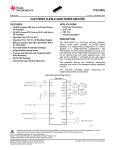
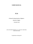
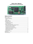
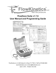
BarrettHand
Control GUI Manual
Version 4.4.3
BarrettHand Control GUI Manual
[email protected]
www.barrett.com
Table of Contents
List of Figures/Equations..............................................................................................3
1 INTRODUCTION...........................................................................................................4
2 CONFIGURE TAB..........................................................................................................5
2.1 CONFIGURATION.............................................................................................................6
2.2 TEST DELAYS................................................................................................................7
2.3 UPLOAD FIRMWARE TO HAND..........................................................................................9
3 SUPERVISE TAB..........................................................................................................11
3.1 TERMINAL...................................................................................................................12
3.2 CONTROL PANEL..........................................................................................................14
3.2.1 Parameters..................................................................................................16
4 REAL TIME TAB..........................................................................................................17
4.1 REAL TIME CONTROL...................................................................................................18
4.1.1 Expression Syntax.....................................................................................21
4.1.2 Data From File...........................................................................................23
5 REAL TIME PLOT DATA TAB....................................................................................25
5.1 PLOT DATA.................................................................................................................25
6 VISUAL TAB................................................................................................................27
6.1 VISUAL CONTROL........................................................................................................28
© 2010 Barrett Technology ®, Inc
back to top
2 of 31
BarrettHand Control GUI Manual
[email protected]
www.barrett.com
List of Figures/Equations
Figure 1 – Configure Tab.....................................................................................................5
Figure 2 – Configure Tab – Configuration...........................................................................6
Figure 3 – Configure Tab – Test Delays..............................................................................7
Figure 4 – Configure Tab – Upload Firmware to Hand.......................................................9
Figure 5 – Configure Tab – BH8-262 Upload Firmware Message Box..............................9
Figure 6 – Configure Tab – BH8-280 Upload Firmware Message Box............................10
Figure 7 – Configure Tab – Uploading Firmware Complete.............................................10
Figure 8 – Supervise Tab....................................................................................................11
Figure 9 – Supervise Tab – Terminal.................................................................................12
Figure 10 – Supervise Tab – Control Panel.......................................................................14
Figure 11 – Supervise Tab – Properties Box......................................................................16
Figure 12 – Real Time Tab.................................................................................................17
Figure 13 – Real Time Tab – Real Time Control Box.......................................................18
Equation 1 – Real Time Tab – Real Time Velocity Control...............................................18
Figure 14 – Real Time Tab – Data From File Box.............................................................23
Figure 15 – Real Time Tab – Data From File as Control Velocity....................................24
Figure 16 – Real Time Plot Data Tab.................................................................................25
Figure 17 – Real Time Plot Data Tab – Save Plot.............................................................26
Figure 18 – Visual Tab.......................................................................................................27
Figure 19 – Visual Tab – Multiple Selection.....................................................................28
Figure 20 – Visual Tab – OpenGL Window Features........................................................29
Figure 21 – Visual Tab – Strain and Pressure Profile Sensors...........................................31
© 2010 Barrett Technology ®, Inc
back to top
3 of 31
BarrettHand Control GUI Manual
[email protected]
www.barrett.com
1 Introduction
The BarrettHand Control GUI is a cross-platform software application designed
for the BarrettHand. This software provides functionality of the BarrettHand API
through an intuitive graphical user interface (GUI). The BarrettHand Control GUI can be
used to help develop, test, and debug projects related to the BarrettHand.
This application includes five sections:
1. Configure – Initialize communication with the hand, test transmission delays, and
upload firmware.
2. Supervise – Issue supervisory mode commands, test command sequences, load
previously saved command sequences, and generate C++ code along with a
makefile for standalone programs.
3. Real Time – Issue RealTime mode commands, test control laws, load previously
saved control laws, and generate C++ code along with a makefile for standalone
programs.
4. Real Time Plot Data – Run RealTime mode commands specified in the Real Time
tab, graph real-time plot data based on feedback and control signals, and save plot
data to a .csv file.
5. Visual – Visualize the hand and interact with hand components. Control fingers
simultaneously by selecting multiple components.
The BarrettHand Control GUI is programmed using the wxWidgets Library.
Toolbars, buttons, text windows, etc. are native to the operating system currently being
used. The BarrettHand Control GUI contains tabs corresponding to each section,
allowing for easy navigation within the GUI. When the application starts the GUI will
not be able to do much until the hand is initialized. Once the hand is initialized, the tabs
and buttons will be enabled.
Note: The minimum recommended resolution for the BarrettHand Control GUI is
1024x768.
© 2010 Barrett Technology ®, Inc
back to top
4 of 31
BarrettHand Control GUI Manual
[email protected]
www.barrett.com
2 Configure Tab
Figure 1 – Configure Tab
© 2010 Barrett Technology ®, Inc
back to top
5 of 31
BarrettHand Control GUI Manual
[email protected]
www.barrett.com
2.1 Configuration
Figure 2 – Configure Tab – Configuration
The Configuration box initializes the BarrettHand with the necessary
communication settings after the Initialize Library button is clicked.
Model Num:
The user needs to identify the model number of the hand that they will use by selecting
either the BH8-262 or BH8-280 hand in this list box.
CAN/Serial:
Serial communication is the only available option for the BH8-262 hand. CAN
communication is the default option for the BH8-280 hand. The support for serial
communication for the new BH8-280 hand is limited.
Auto-Init Hand:
If Auto-Init Hand is checked, the BarrettHand will automatically initialize its motors after
initializing the library. If Auto-Init Hand is unchecked, motors will need to be initialized
manually through the Supervisory Tab.
Com Port:
The Com Port determines the serial port to use to communicate with the BarrettHand.
Once the BarrettHand is initialized changing the Com Port selection will have no effect.
Baud Rate:
The Baud Rate specifies the bits of data per second sent over serial. The default value for
the Baud Rate is 9600. Setting this before initializing library will change the baud rate
that the GUI uses to connect to the hand. Increasing the baud rate after will change the
both the hand and the rate that the GUI connects to the hand immediately.
© 2010 Barrett Technology ®, Inc
back to top
6 of 31
BarrettHand Control GUI Manual
[email protected]
www.barrett.com
Initialize Library:
This button initializes the BarrettHand Library. Once clicked, it initializes
communication port parameters, resets internal variables, clears all buffers, and starts a
low-level communications thread.
Reset Defaults:
This button issues a reset command to the hand and resets the Baud Rate to the default
value of 9600. Resetting the hand does not re-initialize the library, however. Motors will
need to be re-initialized if the BarrettHand is reset; the GUI will automatically reinitialize
motors if Auto-Init Hand is checked when Reset Defaults is clicked.
2.2 Test Delays
Figure 3 – Configure Tab – Test Delays
The Test Delays box records communication delay with the BarrettHand in
RealTime mode. Communication delay is the actual time measured for a control loop
update. This is the period between a control block being sent and a feedback block being
received if using serial. If CAN is used, this is the amount of time it takes to send control
data and receive feedback data. Library communication delay, CPU processing, and hand
processing are also part of the communication delay. One-hundred delays are measured.
The delay times will vary depending on which parameters are selected within the Test
Delays box. When recording is over, a Delay Histogram is rendered to display a
distribution of delay times.
© 2010 Barrett Technology ®, Inc
back to top
7 of 31
BarrettHand Control GUI Manual
[email protected]
www.barrett.com
Motors:
These check boxes specify which motors will be enabled in RealTime mode while the
communication delays are being tested. Selected motors will be included in each control
loop update so motor control data will be sent and motor feedback data will be received.
Control:
The velocity check box specifies a control velocity to be sent to the BarrettHand in a
control loop update. More options may exist such as a proportional control gain for the
BH8-262 hand. These control settings can be enabled by checking the boxes. Invalid
input in the text window for velocity control will default to 0. Proportional Gain is
currently set at 8 for the BH8-262 hand. Although there may be other control references
such as torques or positions for the BH8-280 these are not listed.
Feedback:
These check boxes specify parameters the BarrettHand can return in a feedback block.
Checked parameters will be sent from the BarrettHand in RealTime mode. Note that
delta position feedback is only an option for the BH8-262.
Test Delays:
In order to use Test Delays, first select desired motors. Next, enable desired control and
feedback parameters. Once Test Delays is clicked, the GUI will enable RealTime mode
on the BarrettHand and measure one-hundred delays. RealTime mode is stopped once
the delays are measured.
Results:
The Results Box displays minimum delay time (Min), maximum delay time (Max),
average delay time (Avg.).
Delay Histogram:
The Delay Histogram displays a bar graph representing the number of delays recorded at
each time interval. The graph features panning, zooming, scaling, etc. All features are
shown by right clicking anywhere in the Delay Histogram window and selecting “Show
Mouse Commands”.
© 2010 Barrett Technology ®, Inc
back to top
8 of 31
BarrettHand Control GUI Manual
[email protected]
www.barrett.com
2.3 Upload Firmware to Hand
Figure 4 – Configure Tab – Upload Firmware to Hand
During library initialization, the program will show an error message if the
BarrettHand has an outdated or invalid .S19 file. If an older version of the firmware is
detected or the memory on the BH8-262 BarrettHand has decayed, valid firmware will be
required for the BarrettHand to operate correctly. The selected model number in the
Configuration group box will determine which hand to upload firmware to.
Browse:
This button will open a file dialog box. Once the file dialog is open, the user can find and
select a firmware file to upload to the hand. Firmware files have a .S19 extension for the
BH8-262 and .TEK for the BH8-280. The Current Path and Current File fields in the GUI
will update accordingly.
Upload:
This button will upload firmware to the hand. When clicked, a dialog box will prompt
the user to power off the BH8-262 BarrettHand. Once the BarrettHand is powered off
and the user clicks “Ok”, a message will appear, signaling the user to power the
BarrettHand back on. If the bootloader is configured for the BH8-280 hand then then no
power cycle is required and the hand only needs to be powered up for a few seconds.
Figure 5 – Configure Tab – BH8-262 Upload Firmware Message Box
© 2010 Barrett Technology ®, Inc
back to top
9 of 31
BarrettHand Control GUI Manual
[email protected]
www.barrett.com
Figure 6 – Configure Tab – BH8-280 Upload Firmware Message Box
Once the user powers the BH8-262 BarrettHand back on or clicks the OK button of the
BH8-280 message box, the GUI will disable all features and the progress bar will update
accordingly. Do NOT attempt to power off the hand or close the program while the
firmware is uploading to the BarrettHand as potential damage could be caused to the
hardware. The user should not multi-task while uploading firmware because this may
cause problems uploading firmware. Therefore, the user should leave the GUI as the top
Window. If the progress bar does not move for 30 seconds then the connection is
probably broken so the GUI and the firmware upload should be restarted. Once the
firmware upload is complete, the GUI will be re-activated. If the library was not
initialized before uploading firmware to the hand, click the Initialize Library button after
the firmware has been uploaded. Once the library is initialized, the Firmware On Hand
field will display the current version of the firmware on the hand.
If the library was already initialized for the BH8-262 before uploading firmware, then the
motors need to be initialized again (they can be initialized through the Supervise Tab). If
the BH8-280 hand was already initialized then the GUI needs to be restarted to wake up
the pucks with Initialize Library button.
Figure 7 – Configure Tab – Uploading Firmware Complete
© 2010 Barrett Technology ®, Inc
back to top
10 of 31
BarrettHand Control GUI Manual
[email protected]
www.barrett.com
3 Supervise Tab
Figure 8 – Supervise Tab
© 2010 Barrett Technology ®, Inc
back to top
11 of 31
BarrettHand Control GUI Manual
[email protected]
www.barrett.com
3.1 Terminal
Figure 9 – Supervise Tab – Terminal
From the Terminal Box the user can send supervisory commands in the Command
Buffer text window (non – RealTime commands) to the BarrettHand. Supervisory
commands, in ASCII format, are parsed and call BarrettHand functions.
Command Buffer:
The Command Buffer text window handles all information sent to the hand. The user can
populate the window with commands by either clicking buttons in the Supervise Control
Panel or typing in commands manually. Each time a command is executed, it will be
transferred from the Command Buffer window to the Session History window.
Session History:
The Session History text window records all commands issued from the Command
Buffer window. The Session History window can toggle between ASCII or C++ versions
of the supervisory commands.
Run:
The Run button will execute all commands from the Command Buffer window one at a
time. Supervisory commands will continue executing until the Command Buffer window
is empty or an error is returned.
Abort:
This button will stop the command buffer from running any more commands.
© 2010 Barrett Technology ®, Inc
back to top
12 of 31
BarrettHand Control GUI Manual
[email protected]
www.barrett.com
Auto Run:
If the Auto Run check box is enabled, hitting <Enter> key while in the Command Buffer
window will automatically run all supervisory commands currently listed. Also, any
buttons clicked from the Control Panel box will automatically execute. If Auto Run is
not checked, buttons clicked from the Control Panel box will accumulate in the
Command Buffer window. The Command Buffer's contents can be executed by clicking
the Run button. Toggling the Auto Run box to be checked is the same as hitting the Run
button.
Clear Session / Clear Buffer:
Each button clears its respective window.
Load / Save:
These buttons load and save “.bh” files, which are a list of ASCII commands. Commands
can be loaded to or saved from the Command Buffer in this format. Loading a file will
completely overwrite the contents previously stored in the Command Buffer window.
Copy:
Copying of files can be done in two methods. Keyboard shortcuts for copy <Ctrl-C> and
then paste <Ctrl-V> can be used to copy text from the Session History window to the
Command Buffer window. Note, the Session History window is read-only. The
alternative method is using the Copy button. If no text is selected, pressing the copy
button will copy all the contents of the Session History window into the Command
Buffer. Otherwise, the copy button will only copy selected text into the Command Buffer
window. The Copy button is usable only when the ASCII radio button is selected.
Generate C++:
This button will generate a C++ program that executes the sequence of supervisory
commands listed in the Session History window. The program will initialize the
BarrettHand and the library, along with handling errors accordingly. A corresponding
Makefile will be generated as well. For example, if a “file.cpp” is generated, a Makefile
named “file.mak” will also be created.
The Makefile links automatically to the location of the BHControl's BarrettHand Library
(assuming BHControl was run from BHControl, BHControl/bin/Debug,
BHControl/bin/Release, or BHControl/bin). To make the file, navigate to where the
“file.cpp” is located (via a terminal or a windows command prompt) and simply type in:
make -f file.mak
(for Linux)
mingw32-make -f file.mak ARCH=windows
(for Windows)
or
© 2010 Barrett Technology ®, Inc
back to top
13 of 31
BarrettHand Control GUI Manual
[email protected]
www.barrett.com
3.2 Control Panel
Figure 10 – Supervise Tab – Control Panel
The Control Panel contains all the buttons corresponding to Supervisory mode
command provided by the BarrettHand library. The buttons on the left side of the
Control Panel contain the commands that move the motors. First, select which motors to
control and then press the desired command button. At least one motor must be selected
to enable the command buttons.
Buttons:
Function
Initialize
Stop Motor
Initializes the selected motors
Idles the selected motors
Open
Actuates selected motors to open corresponding fingers or spread
Close
Actuates selected motors to close corresponding fingers or spread
Torque Open
Commands velocity of motors that opens the corresponding fingers
or spread with control of motor torque at stall
Torque Close
Commands velocity of motors that closes the corresponding fingers
or spread with control of motor torque at stall
Go Home
Opens all fingers and the spread, regardless of motors selected
Go Default
Moves selected motors to the default position, DP
Default
Loads the default parameters from the EEPROM for the selected
motors
© 2010 Barrett Technology ®, Inc
back to top
14 of 31
BarrettHand Control GUI Manual
[email protected]
www.barrett.com
Buttons (cont'd):
Function
Load
Loads the active parameters from the EEPROM for the selected
motors
Save
Saves the active parameters to EEPROM for the selected motors
Go Position
Moves the selected motors to the position indicated by the above
text window
Moves the selected motors in the open direction by the number of
encoder counts in the above text window
Step Open
Step Close
Moves the selected motors in the close direction by the number of
encoder counts in the above text window
Delay
Inserts a delay sequence equal to the number of milliseconds
specified by the corresponding text window
Temperature
Shows the present temperature of the internal electronic boards of
the BarrettHand
© 2010 Barrett Technology ®, Inc
back to top
15 of 31
BarrettHand Control GUI Manual
[email protected]
www.barrett.com
3.2.1 Parameters
Figure 11 – Supervise Tab – Properties Box
The Properties box is able to get and set hand properties. The category list box
helps divide the available properties into a smaller number identified by a category label.
Available properties will depend on the hand model number. A desired property can be
chosen first selecting the category and then the property from the list boxes. The user can
enable and disable selected motor values of get/set by toggling the check boxes.
Get:
This button gets parameters for the selected motors. Regardless of the Auto Run check
box state, the selected motors' text windows will update accordingly with the value of the
selected parameter. If Auto Run is unchecked, the supervisory commands to get the
values will appear in the command buffer as well.
Set:
This button sets parameters for the selected motors. If Auto Run is selected, the values of
selected motors' chosen parameter will be set to the values in the text windows.
Otherwise, the command buffer will append the supervisory commands to set the motors'
chosen parameter. Some parameters are read-only; the Set Button will be enabled only if
the user is allowed to change the value of the chosen parameter.
Set DP and Go:
This button functions the same as the Set button. It is only usable if the Default Position
(DP) parameter is selected. Set DP and Go will both set the selected motors' default
position to values specified and then the selected motors will move to the new default
position immediately.
© 2010 Barrett Technology ®, Inc
back to top
16 of 31
BarrettHand Control GUI Manual
[email protected]
www.barrett.com
4 Real Time Tab
Figure 12 – Real Time Tab
© 2010 Barrett Technology ®, Inc
back to top
17 of 31
BarrettHand Control GUI Manual
[email protected]
www.barrett.com
4.1 Real Time Control
Figure 13 – Real Time Tab – Real Time Control Box
The Real Time Control Panel is used to create control laws for the fingers and
spread. Real Time control is useful when immediate control of the motor velocity is
desired. Unlike supervisory mode, the Real Time mode allows the user to change the
velocity while the motors are still moving. The eight expression fields (top right) define
the Control Velocity and Control Proportional Gain signals to be sent to the motors at
each time step. The Control Proportional Gain and Real Time Multiplier parameters are
only available on the BH8-262. Select the desired motors and control parameters by
checking the motor number, Control Velocity, and Control Proportional Gain check
boxes. Enter an expression in the enabled fields. The expressions can include feedback
variables, time, constants, and numeric sequences loaded from a file, see Section 4.1.1.
The BH8-262 velocity of a given motor will respond according to the control law in
Equation 1.
Mcn = (K/4) * Yn
Equation 1 – Real Time Tab – Real Time Velocity Control
Where:
MCn is the motor command output.
K is the proportional gain calculated from the Control Proportional Gain expression.
Yn is the (Control Velocity expression * CVel Multiplier – Actual Velocity).
© 2010 Barrett Technology ®, Inc
back to top
18 of 31
BarrettHand Control GUI Manual
[email protected]
www.barrett.com
Velocity control for the BH8-280 hand is implemented with a position controller
updated at a kilohertz. Each servo loop, the velocity reference (in units of ticks/ms) is
added to the present commanded position.
After the chosen expression windows have been filled in, select the desired
feedback parameters and multipliers in the Real Time Parameters section. Multipliers
will only have an affect on the BH8-262 hand. The following is a list of the parameters
and their definitions:
Parameter:
Definition
Position
Motor Position Feedback
Velocity
Motor Velocity Feedback
Strain
Delta
Finger Strain Gauge Feedback
Motor Delta Position Feedback (BH8-262 only)
FVel Multiplier
The BarrettHand divides the Actual Veloctiy by FVel Multiplier
before sending the Velocity Feedback to the host computer.
Velocity Feedback = Actual Velocity / FVel Multiplier
Delta Multiplier
The BarrettHand divides the Actual Delta Position by Delta
Multiplier before sending the Delta Position Feedback to the host
computer.
Delta Position Feedback = Actual Delta Position / Delta Multiplier
CVel Multiplier
After receiving the Control Velocity, the BarrettHand multiplies
the Control Velocity by CVel Multiplier to determine the
Command Velocity to control the BarrettHand.
Control Velocity * CVel Multiplier = Command Velocity
After the Real Time Parameters have been set, a Termination Condition must be
provided. Real Time mode will stop running once the Termination Condition evaluates to
TRUE. The Termination Condition can include all the variables supported by the Control
Velocity and Control Proportional Gain expressions (refer to Section 4.1.1).
Execute Before / Execute After:
These two text windows on the left side of the Real Time Control box support
supervisory ASCII commands. If Execute Before is checked, the supervisory commands
in that text window will be executed before Real Time control is started. If Execute After
is checked, the supervisory commands in that text window will be executed after Real
Time control is complete. Commands can be entered into these text windows via typing
directly or loading from a file created within the Supervise Tab. See the BarrettHand
User Manual for more information on specific BarrettHand commands.
© 2010 Barrett Technology ®, Inc
back to top
19 of 31
BarrettHand Control GUI Manual
[email protected]
www.barrett.com
Data From File:
Values loaded from a file can be used in the expressions in Real Time mode. Refer to
Section 4.1.2 for more information regarding file format.
Run:
Once run is clicked, if Execute Before is checked, those supervisory commands will be
run. The expressions will be parsed into a tree and variables will be substituted
recursively through the nodes of the tree. If any syntax errors are found, Real Time mode
will stop. At each time step the program evaluates the enabled expressions to obtain
desired control signals, sends them to the hand, and reads the feedback variables that
have been activated. The Termination Condition (always required) is evaluated at each
time step. If the Termination Condition is true, real time mode is aborted. Then, if
Execute After is checked, the corresponding supervisory commands are issued. If at any
time any error occurs, the entire process will stop immediately and Run will need to be
hit again to restart the process.
Abort:
The Abort button will stop the Run process immediately as well.
The combination of settings in the Real Time Control box defines a user “program” that a
built-in interpreter executes in real-time to control the hand.
Save Code:
This button saves the settings/expressions of the Real Time Control box to a file.
Load Code:
This button loads the settings/expressions from a file into the Real Time Control box.
Clear Code:
This button clears the settings/expressions of the Real Time Control box to its defaults.
Generate C++:
This button will generate a C++ program that translates the Real Time Control box
settings into a C++ program along with Execute Before and Execute After supervisory
commands. The program will initialize the BarrettHand and the library, along with
handling errors accordingly. A corresponding makefile will be generated as well. For
example, if “file.cpp” is generated, a makefile named “file.mak” will also be created.
The makefile links automatically to the location of the BHControl's BarrettHand Library
(assuming BHControl was run from BHControl, BHControl/bin, BHControl/bin/Debug,
BHControl/bin/Release). To make the file, navigate to where “file.cpp” is located via a
terminal or a windows command prompt and simply type in:
© 2010 Barrett Technology ®, Inc
back to top
20 of 31
BarrettHand Control GUI Manual
[email protected]
www.barrett.com
make -f file.mak
(for Linux)
mingw32-make -f file.mak ARCH=windows
(for Windows)
or
4.1.1 Expression Syntax
The expressions used for Real Time control follow a C-style syntax. The program
will return an error if the syntax is incorrect. The expressions are checked when the user
attempts to Run the program. All activated fields must have expressions entered.
The expressions are made of variables, functions, and operators. All variables
(predefined) are internally stored as integers. At the beginning of each update, they are
converted to double-precision floating point numbers used in all expression evaluations.
The resulting evaluation is rounded to the nearest integer.
Variables:
D
F
N
P
S
T
V
Delta Positon
File Data (0 is no file is opened)
Update Number
Position
Strain
Time elapsed in milliseconds since RealTime control began
Velocity
Each variable can be used with a subscript. For example, P1 refers to the position
of finger 1 in all expression fields. If the variable does not include a subscript, its value
will correspond to the motor value of the text window it is located in. For example, if P
is used in the Motor 2 Velocity Control expression field, then P refers to P2 – the position
of motor 2. If a variable is used without a subscript in the Termination Condition, it will
default to motor 1's value. Although lower case variables can be used, only upper case
variables will correctly translate into a generated C++ file.
Functions:
abs(x)
acos(x)
asin(x)
atan(x)
ceil(x)
cos(x)
exp(x)
floor(x)
log(x)
ln(x)
Returns the absolute value of x
Returns the Arc-Cosine of x
Returns the Arc-Sin of x
Returns the Arc-Tax of x
Returns the smallest integer greater than x
Returns the Cosine of x
Returns the value e^x
Returns the largest integer smaller than x
Returns the Log, base 10, of x
Returns the Natural Log of x
© 2010 Barrett Technology ®, Inc
back to top
21 of 31
BarrettHand Control GUI Manual
random(x)
round(x)
sin(x)
sqrt(x)
tan(x)
[email protected]
www.barrett.com
Generates a uniformly distributed real number between zero and x
Returns the integer closest to x
Returns the Sine of x
Returns the square root of x
Returns the Tangent of x
Note: All trigonometric functions are in radians
Arithmetic Operators (in order of precedence):
^
*
/
%
+
–
Exponentiation
Multiplication
Division
Modulus (A % B = remainder of A divided by B) (works for floats)
Addition
Subtraction
Parentheses can be used to change precedence. Note, in order to negate values, an
extra set of parentheses must be included around the value that is to be negated. For
example, “5 + -5” must be entered in the expression window as “5 + (-5)”.
Logical Operators:
!
&&
||
Not
And
Or
Parentheses should be used to explicitly define expressions. For example, the
expression 50 && 25 > 10 can evaluate to both TRUE and FALSE. The expression
(50 && 25) > 10 will yield FALSE and 50 && (25 > 10) will yield TRUE.
Comparison Operators:
>=
Greater than or equal to
<=
Less than or equal to
!=
Not equal to
<
Less than
>
Greater than
==
Equal to
Once again, use Parentheses to explicitly define the two values being compared.
Conditional Expression Operator:
expression ? value1 : value2
If the expression is true, the statement evaluates to value1, otherwise to value2.
Parentheses must be used to denote the fields expression, value1, and value2.
© 2010 Barrett Technology ®, Inc
back to top
22 of 31
BarrettHand Control GUI Manual
[email protected]
www.barrett.com
4.1.2 Data From File
Figure 14 – Real Time Tab – Data From File Box
The user can specify a data file to be used in expressions by loading a file into the
Real Time Tab. The format of the file, Real Time Data (.rtd), should contain a table of
numbers with four tab-delimited columns and any number of rows, N. The variable F1
will evaluate to column 1, row number equal to the present update step. F2 will evaluate
to column 2, row number equal to the present update step, etc. If the update step is
larger than the last row, the update number = update number % total rows in the file.
Here is an example:
File Data:
30
30
50
50
50
100
100
100
40
40
0
0
0
0
0
35
35
35
35
35
© 2010 Barrett Technology ®, Inc
back to top
23 of 31
BarrettHand Control GUI Manual
[email protected]
www.barrett.com
Set Control Velocity / Proportional Gain expressions accordingly:
Figure 15 – Real Time Tab – Data From File as Control Velocity
Note that for the BH8-262, there must be some Proportional Gain for the motors
to move (refer to Equation 1). Also, not all expression windows have to be enabled to
use Data From File variables. Each time control velocities are sent to the BarrettHand as
follows:
Update Step
1
2
3
4
5
6
7
8
9
10
etc.
© 2010 Barrett Technology ®, Inc
F1
30
30
50
50
50
30
30
50
50
50
etc.
F2
100
100
100
40
40
100
100
100
40
40
etc.
F3
0
0
0
0
0
0
0
0
0
0
etc.
back to top
F4
35
35
35
35
35
35
35
35
35
35
etc.
24 of 31
BarrettHand Control GUI Manual
[email protected]
www.barrett.com
5 Real Time Plot Data Tab
Figure 16 – Real Time Plot Data Tab
5.1 Plot Data
The Real Time Plots tab is an optional feature usable with Real Time mode. This
tab allows users to visualize data more readily. The Real Time Plots tab plots control and
feedback variables in Real Time as soon as data is received onto the four corresponding
motor graphs. The top graph represents motor one, the second graph represents motor
two, the third graph represents motor three, the fourth graph represents the spread motor.
The graphs resize themselves automatically to get the best fit of the plot data, but the user
is free to pan, zoom, scale to suit his or her needs. Right click on any graph and select
“Show mouse commands...” for instructions.
© 2010 Barrett Technology ®, Inc
back to top
25 of 31
BarrettHand Control GUI Manual
[email protected]
www.barrett.com
List Box:
The list box to the right shows all available variables that can be plotted. Variables in the
list box can be toggled on and off at any time, even while Real Time control is running.
Each variable is plotted in a different color; up to 8 variables can be plotted in the same
graph at once.
Run:
The Run Button is a shortcut that will run programs created in the Real Time Control
panel from within the Real Time Plots panel.
Abort:
Aborts Real Time mode immediately.
Lock Aspect:
This check box will lock/unlock the aspect ratio for all graphs. For variables such as
Time Stamp and Position, it is best to have the aspect ratio unlocked. Lock Aspect is
toggled off by default.
Save Plot:
Save Plot will save all the graph data into a comma separated value “.csv” file. If the N
= and To text windows are non-zero, the “.csv” value will only contain values for that
range of update steps. By default, all values from all update steps are saved to the file.
Inactive motors will have the value of zero for all parameters.
Figure 17 – Real Time Plot Data Tab – Save Plot
An example “.csv” file is as follows:
N, Ctrl_Vel1, Ctrl_Vel2, Ctrl_Vel3, Ctrl_Vel4, Ctrl_Gain1,
0, 6.503930, -5.606993, -64.217316, 0.000000, 40.000000,
1,
8.012341, -7.115150, -64.058426, 0.000000, 40.000000,
2, 9.677564, -8.780029, -63.841507, 0.000000, 40.000000,
3, 11.336661, -10.438716, -63.581650, 0.000000, 40.000000,
4, 12.988526, -12.090102, -63.279037, 0.000000, 40.000000,
5, 14.684925, -13.785931, -62.922020, 0.000000, 40.000000,
© 2010 Barrett Technology ®, Inc
back to top
Ctrl_Gain2,
40.000000,
40.000000,
40.000000,
40.000000,
40.000000,
40.000000,
Ctrl_Gain3,
40.000000,
40.000000,
40.000000,
40.000000,
40.000000,
40.000000,
Ctrl_Gain4
0.000000
0.000000
0.000000
0.000000
0.000000
0.000000
26 of 31
BarrettHand Control GUI Manual
[email protected]
www.barrett.com
6 Visual Tab
Figure 18 – Visual Tab
© 2010 Barrett Technology ®, Inc
back to top
27 of 31
BarrettHand Control GUI Manual
[email protected]
www.barrett.com
6.1 Visual Control
The Visual Tab provides an OpenGL window to interact with the hand. Graphics
drivers are highly recommended in order to have the visual run at a decent frame rate and
will be required to be able to drag fingers inside the OpenGL visual. The BarrettHand
OpenGL model moves and behaves in a similar fashion to the real BarrettHand. Simple
bounding-sphere collision detection, a basic shading model, and rigid-body animation are
implemented in this visualizer.
Users can move the fingers of the hand by right-clicking and holding on a given
finger and then moving the mouse up or down. The finger will close if the mouse is
moved up or vice versa. If the base of fingers 1 or 2 is right-clicked, moving the mouse
left or right will open or close the spread for the hand in the visual, respectively. Release
the right mouse button to have the spread go to the position shown in the visual.
Multiple fingers can be moved simultaneously as well. If the Control key is held
while right clicking on a finger, the finger will change to a shade of blue. Control and
right-clicking on a blue finger will revert the finger back to gray.
Figure 19 – Visual Tab – Multiple Selection
© 2010 Barrett Technology ®, Inc
back to top
28 of 31
BarrettHand Control GUI Manual
[email protected]
www.barrett.com
Show Kinematics:
Checking the Show Kinematics box will display spheres and cylinders that represent the
endpoints contained in the wrist to tool matrices. See the user manual to understand how
to compute these. Move the joints in the visual and watch as the kinematics in OpenGL
windows change. Note that the model and kinematics may only be accurate before
breakaway. In future revisions of the software, we may choose to model both the inner
and outer finger links.
Show Trackball:
To help visualize the rotation, checking the Show Trackball box will display a sphere to
show how mouse movement is associated with the three-dimensional rotations.
Camera/Interact:
The Camera and Interact toggle buttons determine the function of the scroll wheel. If the
Interact button is toggled (on by default), scrolling the mouse wheel up will incrementally
close all selected (blue) fingers. Likewise, scrolling the mouse wheel down will open all
selected (blue) fingers. If the Camera button is toggled, the mouse scroll will zoom the
camera viewing the OpenGL scene in or out.
The OpenGL window also implements trackball rotation, which allows the user to
freely rotate the BarrettHand model in three-dimensions using two-dimensional mouse
movement (implemented with quaternions). Left-clicking and dragging the mouse will
rotate the BarrettHand model.
Here is a screen shot demonstrating camera zoom, multiple finger movement,
camera rotation, and with the Show Trackball check box checked:
Figure 20 – Visual Tab – OpenGL Window Features
© 2010 Barrett Technology ®, Inc
back to top
29 of 31
BarrettHand Control GUI Manual
[email protected]
www.barrett.com
The OpenGL window can interact with the BarrettHand directly. There are two
Supervisory buttons that allow the user to update the hand or the OpenGL model of the
hand.
Go Supervisory:
This button will move the real-life BarrettHand to match the orientation of the OpenGL
model.
Refresh OpenGL:
This button will Refresh the OpenGL window to match the orientation of the real-life
BarrettHand.
The BarrettHand can also be controlled in the Visual tab while the OpenGL model
updates in real-time. This mode is activated by clicking on the Start RTControl toggle
button. In velocity mode, the fingers are controlled in RealTime with position-mode PID
controllers for fingers that compute desired control velocities. Spread is controlled in
position mode and is commanded to change position when the slider for spread is
released or the right mouse button is released after the spread position has changed.
Start RTControl/Abort RTControl:
This button will first enter Real Time mode and move the real-life BarrettHand to match
the orientation of the BarrettHand OpenGL model. Then, any movements made within
the OpenGL model will be mimicked by the real-life BarrettHand. This button functions
as a toggle button to start and abort RealTime control of the BarrettHand in the Visual
tab. Parameters for RealTime control of the hand are updated when this toggle button is
pressed to start RealTime control.
RealTime Control Parameters:
The user may set proportional and derivative (PD) gains for the position controller that is
used to control the fingers velocities. For the 262 hand RTGain is a proportional control
gain for the hand motors that amplifies the actual control velocity. LCV (loop control
velocity) is also a proportional control gain that will amplify the actual control velocity.
Visual mode:
In general, the hand should be controlled with velocities in the visual tab for smoothest
movement and is the only option for a 262 hand. A 280 hand may be visually controlled
in velocity, position, or torque mode. Reference positions for the model are submitted to
another thread that executes with high priority so that the servo-rate is much higher than
it would be otherwise. Position mode may have non-smooth movement because the
model itself gets updated with slower mouse movements. Torque and position modes are
mainly implemented to illustrate how the user may get started writing their own position
or torque controllers in a separate thread.
© 2010 Barrett Technology ®, Inc
back to top
30 of 31
BarrettHand Control GUI Manual
[email protected]
www.barrett.com
RealTime Control Sliders:
Dragging these sliders will update the positions of the fingers in RealTime or give the
spread a new position to go to. These sliders will also be updated with position changes
to the hand when dragging the fingers and spread in the OpenGL window.
Display Options:
Display options should be selected before entering RealTime control of the hand.
Strain is visually represented on the model of the hand by a line segment drawn near the
finger tips that is proportional in length to the amount of strain. Tare the strain
measurement by clicking on the button near the strain check box.
Figure 21 – Visual Tab – Strain and Pressure Profile Sensors
Pressure Profile Sensors (PPS) are available as an option on the 280 hand only. The
visual will let users visualize these sensors whether or not the user really has these
sensors. The fingertips and palm will be dark blue and light up based on the amount of
pressure applied.
© 2010 Barrett Technology ®, Inc
back to top
31 of 31