1
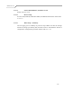
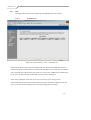
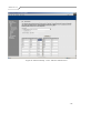
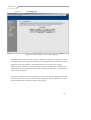
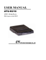
USER MANUAL
ATU-R210
ADSL2+ Bridge/Router
With 4-ports switch HUB
Manual Ver1.01
Table of Contents
1.
INTRODUCTION......................................................................................................................5
2.
INSTALLATION........................................................................................................................6
FRONT PANEL ....................................................................................................................................6
REAR PANEL......................................................................................................................................6
CONNECTING THE HARDWARE .................................................................................7
Step 1. Connect the ADSL cable and optional telephone. .............................................8
Step 2. Connect the Ethernet cable. ....................................................................................8
Step 3. Attach the power connector.....................................................................................8
Step 4. Turn on the ATU-R210 and power up your systems. ........................................8
Step 5. Configure the ATU-R210 through the WEB interface ......................................8
Step 6. Save the configurations and Reboot. ....................................................................8
3.
CONFIGURATION ...................................................................................................................9
3.1
SETUP ...................................................................................................................................9
3.2
ESTABLISH THE CONNECTION ...............................................................................................9
3.3
QUICK SETUP ......................................................................................................................12
3.3.1
PPPover Ethernet (PPPoE) Configuration ...............................................................13
3.3.1.1
3.3.1.2
3.3.1.3
3.3.1.4
ATM PVC Configuration .......................................................................................13
Connection Type and Encapsulation Mode............................................................14
PPP Username and Password.................................................................................15
Enable IGMP Multicast, and WAN service ...........................................................16
3.3.1.5 Device Setup ..........................................................................................................17
3.3.1.6 WAN Setup – Summery.........................................................................................18
3.3.2
IP over ATM (IPoA) Configuration ...........................................................................19
3.3.2.1 ATM PVC Configuration .......................................................................................19
3.3.2.2
3.3.2.3
3.3.2.4
3.3.2.5
Connection Type ....................................................................................................20
WAN IP Settings ....................................................................................................21
NAT, IGMP Multicast, and WAN service ..............................................................22
Device Setup ..........................................................................................................23
3.3.2.6 WAN Setup – Summary.........................................................................................24
3.3.3
Bridge Configuration .................................................................................................25
3.3.3.1 ATM PVC Configuration .......................................................................................25
3.3.3.2 Connection Type ....................................................................................................26
3.3.3.3
WAN Service..........................................................................................................27
-2-
Manual Ver1.01
3.3.3.4 Device Setup ..........................................................................................................28
3.3.3.5 WAN Setup – Summery.........................................................................................29
3.3.4
MAC Encapsulation Routing (MER) Configuration..................................................30
3.3.4.1 ATM PVC Configuration .......................................................................................30
3.3.4.2
3.3.4.3
3.3.4.4
3.3.4.5
Connection Type ....................................................................................................31
WAN IP Settings ....................................................................................................32
NAT, IGMP Multicast, and WAN service ..............................................................33
Device Setup ..........................................................................................................33
3.3.4.6 WAN Setup – Summery.........................................................................................33
3.3.5
PPP over ATM (PPPoA) Configuration ....................................................................34
3.3.5.1 ATM PVC Configuration .......................................................................................34
3.3.5.2 Connection Type ....................................................................................................34
3.3.5.3
3.3.5.4
3.3.5.5
3.3.5.6
PPP Username and Password.................................................................................34
IGMP Multicast, and WAN service........................................................................34
Device Setup ..........................................................................................................34
WAN Setup – Summery.........................................................................................34
3.4
ADVANCED SETUP ...............................................................................................................35
3.4.1
WAN ...........................................................................................................................36
3.4.2
LAN ............................................................................................................................36
3.4.3
NAT ............................................................................................................................37
3.4.3.1 Virtual Servers........................................................................................................37
3.4.3.2 Port Triggering .......................................................................................................39
3.4.3.3 DMZ Host ..............................................................................................................41
3.4.4
Security.......................................................................................................................42
3.4.4.1 Outgoing IP Filtering .............................................................................................42
3.4.4.2 Incoming IP Filtering .............................................................................................43
3.4.4.3 MAC Filtering........................................................................................................44
3.4.5
Routing .......................................................................................................................46
3.4.5.1 Default Gateway ....................................................................................................46
3.4.5.2 Static Route ............................................................................................................47
3.4.5.3 RIP .........................................................................................................................49
3.4.6
DNS Server.................................................................................................................50
3.4.7
DSL ............................................................................................................................52
3.5
DIAGNOSTICS ......................................................................................................................54
3.6
MANAGEMENT ....................................................................................................................54
3.6.1
Settings–Backup/Update Settings and Reset to Default.............................................55
3.6.2
3.6.3
System Log .................................................................................................................57
SNMP Agent ...............................................................................................................58
-3-
Manual Ver1.01
3.6.4
3.6.5
3.6.6
Access Control–Services, IP addresses, and Passwords............................................59
Update Software.........................................................................................................62
Save / Reboot..............................................................................................................63
-4-
Manual Ver1.01
1. Introduction
Congratulations on becoming the owner of the ATU-R210 ADSL Ethernet bridge/router. Your
LAN (local area network) will now be able to access the Internet using your high-speed ADSL
connection. This User Guide will show you how to install and set up your ATU-R210 ADSL
Bridge/Router.
Features
¾ Internal ADSL modem for high speed internet access
¾ 10/100Base-T Ethernet router to provide Internet connectivity to all
computers on your LAN
¾
¾
¾
Network Address Translation (NAT) and IP filtering functions to provide
firewall protection for your computers
Network configuration through DHCP
Configuration program you access via an HTML browser
System Requirements
In order to use your ATU-R210 ADSL/Ethernet router, you must have the following:
¾ ADSL service up and running on your telephone line, with at least one public
¾
¾
Internet address for your LAN
One or more computers each containing an Ethernet 10Base-T/100Base-T
network interface card (NIC)
For system configuration using the supplied web-based program: a web
browser such as Internet Explorer v5.0 or later, or Netscape v4.7 or later
-5-
Manual Ver1.01
2. Installation
In addition to this document, your ATU-R210 should arrive with the following:
¾
¾
One standalone desktop ATU-R210 ADSL Ethernet Bridge/Router
One power adapter
¾
¾
¾
One Ethernet cable
One RJ-11 to RJ-11 telephone Cable
One splitter
Front Panel
The front panel contains lights called LEDs that indicate the status of the unit.
Label
Color
ALARM
Red
Function
Flashes on/off rapidly during the training mode.
Flashes on/off slowly: No ADSL link
Off: ADSL link established and active
ADSL
LINK*
Green
ADSL
ACT
Green
LAN1-4
Green
PWR
Green
On: ADSL link established and active
Off: No ADSL link
Flashes on/off during ADSL data transfer.
On: No data transfer.
On: LAN link established and active
Off: No LAN link
Flashes during data transfer
On: Unit is powered on
Off: Unit is powered off
Rear Panel
The rear panel contains the ports for the unit's data and power connections.
Label
Function
ADSL
RJ-11 connector: Connects the device to a telephone
jack using the supplied cable
On/Off
Switches the unit on and off
PWR
Connects to the supplied power converter cable
LAN1-4
RJ-45 connector:.Connects the device to your PC's
Ethernet port, or to the uplink port on your LAN's hub,
using the cable provided
-6-
Manual Ver1.01
Connecting the Hardware
You connect the device to the phone jack, the power outlet, and your computer or network.
WARNING
Before you begin, turn the power off for all devices. These
include your computer(s), your LAN hub/switch (if applicable),
and the ATU-R210.
Figure 1 illustrates the hardware connections. The layout of the ports on your
device may vary from the layout shown. Refer to the steps that follow for
specific instructions.
Telephone
PSTN
To PC Ethernet
10/100Base-T NIC
Power
Power Switch
Figure 1. Overview of Hardware Connections
-7-
Manual Ver1.01
Step 1. Connect the ADSL cable and optional telephone.
Connect one end of the provided phone cable to the port labeled ADSL on the rear panel of the
device. Connect the other end to your wall phone jack.
You can attach a telephone line to the device. This is helpful when the ADSL line uses the only
convenient wall phone jack. If desired, connect the telephone cable to the port labeled PHONE.
WARNING
Although you use the same type of cable, The ADSL and
PHONE ports are not interchangeable. Do not route the ADSL
connection through the PHONE port.
[CT1]: This warning
assumes that the board
contains an internal filter on
the POTS line. If an external
filter is used instead,
Step 2. Connect the Ethernet cable.
document that step here
and remove this warning
If you are connecting a LAN to the ATU-R210 ADSL/Ethernet router, attach one end of a provided Ethernet cable
(with an external filter, the
to a regular hub port and the other to the Ethernet port on the ATU-R210.
ADSL and PHONE ports
are interchangeable).
Step 3. Attach the power connector.
Connect the AC power adapter to the PWR connector on the back of the device and plug in the
adapter to a wall outlet or power strip.
Step 4. Turn on the ATU-R210 and power up your systems.
Press the Power switch on the back panel of the device to the ON position.
Turn on and boot up your computer(s) and any LAN devices such as hubs or switches.
Step 5. Configure the ATU-R210 through the WEB interface
The detail step3 would be described in Chapter3. It would help you configure the ATU-R210 to
meet your need.
Step 6. Save the configurations and Reboot.
To make the settings you made on ATU-R210 take effect.
-8-
Manual Ver1.01
3. Configuration
3.1
3.2
Setup
z Step 1: Connect the ATU-R and PC with a cross-over/straight Ethernet cable.
z
Step 2: Power on the ATU-R.
z
Step 3: The default IP of the ATU-R is 192.168.1.1.
Establish The Connection
z Enter the IP address (default is 192.168.1.1) of ATU-R from the Web Browser..
z
A Dialogue Box will be popped up to request the user to login. (Figure 1)
Figure 1. Authentication
z
Please enter the management username/password into the fields then click on the
OK button (default username/password is admin/admin).
z
If the authentication passes, the home page “Device Info - Summary” will be
displayed on the browser. (Figure 2)
-9-
Manual Ver1.01
Figure 2. ATU-R Home Page
- 10 -
Manual Ver1.01
Link State – Statistics – ADSL
- 11 -
Manual Ver1.01
3.3
Quick Setup
The system administrator can configure the ATU-R remotely or locally via a Web
Browser. Network configuration need to be planned and decided before starting the
configuration procedure.
Quick Setup allows system administrator to select the appropriate operation mode and
configure the corresponding settings step by step to create a connection. The following
five operation modes are supported :
z
PPP over Ethernet (PPPoE)
z
IP over ATM (IPoA)
z
Bridging
z
MAC Encapsulation Routing (MER)
z
PPP over ATM (PPPoA)
- 12 -
Manual Ver1.01
3.3.1
PPPover Ethernet (PPPoE) Configuration
Click on “Quick Setup” in the left frame, and follow the steps below to create a
PPP over Ethernet (PPPoE) connection.
3.3.1.1
ATM PVC Configuration
Figure 3. Quick Setup – ATM PVC Configuration
Give the VPI/VCI values. Please contact you ISP for the information.
Click on “Next” to go to next step.
- 13 -
Manual Ver1.01
3.3.1.2
Connection Type and Encapsulation Mode
Figure 4. Quick Setup – Connection Type and Encapsulation Mode
Select “PPP over Ethernet (PPPoE)”, and the “Encapsulation Mode”. Please
contact you ISP for the information.
Click on “Next” to go to next step.
- 14 -
Manual Ver1.01
3.3.1.3
PPP Username and Password
Figure 5. Quick Setup – PPP Username and Password
Give “PPP Username”, “PPP Password”, “PPPoE Service Name”, and select
“Authentication Method” (AUTO/PAP/CHAP/MSCHAP). Please contact you
ISP for the information.
The “Dial on demand (with idle timeout timer)” function, if checked, a new
setup parameter “Inactivity Timeout (minutes) [1-4320]” will appear for
ATU-R210 to tear down the PPP link automatically if there is no outgoing
packet for the programmed period of time. ATU-R210 set up PPPoE connection
automatically when there does not exist the PPPoE connection in it and user
wants to send traffic to ISP
The users is able to assign some specific ATM PVC(s) to run PPPoE, when
ATU-R210 is with multiple ATM PVC connection
Click on “Next” to go to next step.
- 15 -
Manual Ver1.01
3.3.1.4
Enable IGMP Multicast, and WAN service
Figure 6. Quick Setup – IGMP Multicast, WAN service
Check to Enable/Disable IGMP Multicast and WAN Service.
Click on “Next” to go to next step.
- 16 -
Manual Ver1.01
3.3.1.5
Device Setup (LAN Setup)
Figure 7. Quick Setup – Device Setup
Give IP (LAN IP, default 192.168.1.1) and Subnet Mask (default 255.255.255.0)
to the device.
Select to Disable/Enable DHCP Server, use DHCP Server Relay, and configure
related settings for that mode.
Note that Network Address Translation function (NAT) is default enabled and is
not showing on the page to prevent it from being disabled.
Click on “Next” to go to next step.
- 17 -
Manual Ver1.01
3.3.1.6
WAN Setup – Summery
Figure 8. Quick Setup – WAN Setup – Summary
The last page gives a summary of previous steps. Make sure that the settings
match the settings provided by ISP, and then click on “Save/Reboot” button to
complete the configuration procedure.
- 18 -
Manual Ver1.01
3.3.2
IP over ATM (IPoA) Configuration
Click on “Quick Setup” in the left frame, and follow the steps below to create a
IP over ATM (IPoA) connection.
3.3.2.1
ATM PVC Configuration
Figure 9. Quick Setup – ATM PVC Configuration
Give the VPI/VCI values. Please contact you ISP for the information.
Click on “Next” to go to next step.
- 19 -
Manual Ver1.01
3.3.2.2
Connection Type
Figure 10. Quick Setup – Connection Type and Encapsulation Mode
Select “IP over ATM (IPoA)”, and the “Encapsulation Mode”. Please contact
you ISP for the information.
Click on “Next” to go to next step.
- 20 -
Manual Ver1.01
3.3.2.3
WAN IP Settings
Figure 11. Quick Setup– WAN IP Settings
WAN IP/Subnet Mask, default gateway, and DNS server settings. Please contact
you ISP for the information.
Click on “Next” to go to next step.
- 21 -
Manual Ver1.01
3.3.2.4
NAT, IGMP Multicast, and WAN service
Figure 12. Quick Setup – IPoA – NAT, IGMP Multicast, WAN service
Check to Enable/Disable NAT and Firewall functions.
Use Advanced Setup/Firewall to assign filter rules. Check to Enable/Disable
IGMP Multicast, and WAN Service.
Click on “Next” to go to next step.
- 22 -
Manual Ver1.01
3.3.2.5
Device Setup (LAN Setup)
Figure 13. Quick Setup – Device Setup
Give IP (LAN IP, default 192.168.1.1) and Subnet Mask (default 255.255.255.0)
to the device.
Select to Disable/Enable DHCP Server, use DHCP Server Relay, and configure
related settings for that mode.
Click on “Next” to go to next step.
- 23 -
Manual Ver1.01
3.3.2.6
WAN Setup – Summary
Figure 14 Quick Setup – WAN Setup – Summary
The last page gives a summary of previous steps. Make sure that the settings
match the settings provided by ISP, and then click on “Save/Reboot” button to
complete the configuration procedure.
- 24 -
Manual Ver1.01
3.3.3 Bridge Configuration
Click on “Quick Setup” in the left frame, and follow the steps below to create a Bridging
connection.
3.3.3.1
ATM PVC Configuration
Figure 15. Quick Setup – ATM PVC Configuration
Give the VPI/VCI values. Please contact you ISP for the information.
Click on “Next” to go to next step.
- 25 -
Manual Ver1.01
3.3.3.2
Connection Type
Figure 16. Quick Setup – Connection Type and Encapsulation Mode
Select “Bridging”, and the “Encapsulation Mode”. Please contact you ISP for
the information.
Click on “Next” to go to next step.
- 26 -
Manual Ver1.01
3.3.3.3
WAN Service
Figure 17. Quick Setup – WAN Service
Give a service name (default setting is br_0_33) and check the box to enable
this wan service.
Click on “Next” to go to next step.
- 27 -
Manual Ver1.01
3.3.3.4
Device Setup
Figure 18. Quick Setup – Device Setup
Give LAN IP (default 192.168.1.1) and Subnet Mask (default 255.255.255.0).
Click on “Next” to go to next step.
- 28 -
Manual Ver1.01
3.3.3.5
WAN Setup – Summery
Figure 19 Quick Setup – WAN Setup – Summary
The last page gives a summary of previous steps. Make sure that the settings
match the settings provided by ISP, and then click on “Save/Reboot” button to
complete the configuration procedure.
- 29 -
Manual Ver1.01
3.3.4
MAC Encapsulation Routing (MER) Configuration
Click on “Quick Setup” in the left frame, and follow the steps below to create a
MAC Encapsulation Routing (MER) connection.
3.3.4.1
ATM PVC Configuration
Figure 20. Quick Setup – ATM PVC Configuration
Give the VPI/VCI values. Please contact you ISP for the information.
Click on “Next” to go to next step.
- 30 -
Manual Ver1.01
3.3.4.2
Connection Type
Figure 21. Quick Setup – Connection Type and Encapsulation Mode
Select “MAC Encapsulation Routing (MER)”, and the “Encapsulation Mode”.
Please contact you ISP for the information.
Click on “Next” to go to next step.
- 31 -
Manual Ver1.01
3.3.4.3
WAN IP Settings
Figure 22. Quick Setup – WAN IP Settings
WAN IP/Subnet Mask, Default Gateway, and DNS Server can either be
obtained automatically or set manually.
Click on “Next” to go to next step.
- 32 -
Manual Ver1.01
3.3.4.4
NAT, IGMP Multicast, and WAN service
Please refer to 3.3.2.4.
3.3.4.5
Device Setup
Set device IP(LAN IP) and Subnet Mask, and DHCP related items. Please refer
to 3.3.1.5.
3.3.4.6
WAN Setup – Summery
The last page gives a summary of previous steps. Make sure that the settings
match the settings provided by ISP, and then click on “Save/Reboot” button to
complete the configuration procedure. Please refer to 3.3.1.6.
- 33 -
Manual Ver1.01
3.3.5
PPP over ATM (PPPoA) Configuration
Click on “Quick Setup” in the left frame, and follow the steps below to create a
PPP over ATM (PPPoA) connection. The following setting steps are all the
same as PPP over Ethernet (PPPoE) steps.
3.3.5.1
ATM PVC Configuration
Give the VPI/VCI values. Please refer to 3.3.1.1.
3.3.5.2
Connection Type
Select “PPP over ATM (PPPoA)”. Please refer to 3.3.1.2
3.3.5.3
PPP Username and Password
Give “PPP Username”, “PPP Password”, and select “Authentication Method”
(AUTO/PAP/CHAP/MSCHAP). Please contact you ISP for the information.
Please refer to 3.3.1.3.
3.3.5.4
IGMP Multicast, and WAN service
Please refer to 3.3.1.4
3.3.5.5
Device Setup
Set device IP (LAN IP) and Subnet Mask, and DHCP related items. Please refer
to 3.3.1.5.
3.3.5.6
WAN Setup – Summery
The last page gives a summary of previous steps. Make sure that the settings
match the settings provided by ISP, and then click on “Save/Reboot” button to
complete the configuration procedure. Please refer to 3.3.1.6.
- 34 -
Manual Ver1.01
3.4
Advanced Setup
Advanced Setup allows system administrator to configure the following topics:
z
WAN
z
LAN
z
NAT
z
Security
z
Routing
z
DNS
z
DSL
- 35 -
Manual Ver1.01
3.4.1
WAN
Figure 23. Advanced Setup – WAN
This page shows the current existing WAN interfaces in the system. User can
choose Add, Edit, or Remove to configure WAN interfaces. For detail about
Add and Edit procedure, please refer to 3.3 Quick Setup.
3.4.2
LAN
Please refer to 3.3.1.5.
- 36 -
Manual Ver1.01
3.4.3
NAT
Including Virtual Servers, Port Triggering, and DMZ Host function settings.
3.4.3.1
Virtual Servers
Figure 24. Advanced Setup – NAT – Virtual Servers
Virtual Server allows you to direct incoming traffic from WAN side (identified by Protocol
and External port) to the Internal server with private IP address on the LAN side. The Internal
port is required only if the external port needs to be converted to a different port number used
by the server on the LAN side. A maximum 32 entries can be configured.
Click on the Add button, select the service you need for this server, then give the
external/internal port and protocol rules(system will show you default configuration for this
service). Click on the Save/Apply button to finish and apply the new setting.
- 37 -
Manual Ver1.01
Figure 25. Advanced Setup – NAT – Add new Virtual Server
- 38 -
Manual Ver1.01
3.4.3.2
Port Triggering
Figure 26. Advanced Setup – NAT – Port Triggering
Some applications require that specific ports in the Router's firewall be opened for access by
the remote parties. Port Trigger dynamically opens up the 'Open Ports' in the firewall when an
application on the LAN initiates a TCP/UDP connection to a remote party using the
'Triggering Ports'. The Router allows the remote party from the WAN side to establish new
connections back to the application on the LAN side using the 'Open Ports'. A maximum 32
entries can be configured.
Click on the Add button, select the application you need, then give the trigger/open port and
protocol rules(system will show you the default configuration for this application). Click on
the Save/Apply button to finish and apply the new setting.
- 39 -
Manual Ver1.01
Figure 27. Advanced Setup – NAT – Add new Port Triggering
- 40 -
Manual Ver1.01
3.4.3.3
DMZ Host
Figure 28. Advanced Setup – NAT – DMZ Host
The DSL router will forward IP packets from the WAN that do not belong to any of the
applications configured in the Virtual Servers table to the DMZ host computer
Enter the computer's IP address and click "Save/Apply" to activate the DMZ host.
Clear the IP address field and click "Save/Apply" to deactivate the DMZ host.
- 41 -
Manual Ver1.01
3.4.4
Security
Two functions are supported in Security, Outgoing IP Filtering and Incoming
IP Filtering.
3.4.4.1
Outgoing IP Filtering
By default, all outgoing IP traffic from LAN is allowed, but some IP traffic can
be blocked by setting up filters. Choose Add or Remove to configure outgoing
IP filters.
Figure 29. Advanced Setup – Firewall – Outgoing IP Filtering Setup
Click on Add to create a filter to identify the outgoing IP traffic by specifying at
least one condition below. If multiple conditions are specified, all of them take
effect
- 42 -
Manual Ver1.01
Figure 30. Advanced Setup – Firewall – Add new Outgoing IP Filter
3.4.4.2
Incoming IP Filtering
By default, all incoming IP traffic from the WAN is blocked when the firewall
is enabled. However, some IP traffic can be Accepted by setting up filters.
Refer to 3.4.4.1 Outgoing IP Filtering, follow the same principle to add a new
filter rule.
- 43 -
Manual Ver1.01
3.4.4.3
MAC Filtering
MAC Filtering is only effective on ATM PVCs configured in Bridge mode.
FORWARD means that all MAC layer frames will be FORWARDED except
those matching with any of the specified rules in the following table.
BLOCKED means that all MAC layer frames will be BLOCKED except those
matching with any of the specified rules in the following table.
Figure 31. Advanced Setup – Firewall – MAC Filtering Setup
Click on Add to create a filter to identify the MAC layer frames by specifying at
least one condition below. If multiple conditions are specified, all of them take
effect.
- 44 -
Manual Ver1.01
Figure 32. Advanced Setup – Firewall – Add new MAC Filter
- 45 -
Manual Ver1.01
3.4.5
Routing
Three routing information related settings are included.
3.4.5.1
Default Gateway
If Enable Automatic Assigned Default Gateway checkbox is selected, this router
will accept the first received default gateway assignment from one of the
PPPoA, PPPoE or MER/DHCP enabled PVC(s). If the checkbox is not selected,
enter the static default gateway AND/OR a WAN interface. Click 'Save/Apply'
button to save it.
NOTE: If changing the Automatic Assigned Default Gateway from unselected
to selected, You must reboot the router to get the automatic assigned default
gateway.
Figure 33. Advanced Setup – Routing – Default Gateway
- 46 -
Manual Ver1.01
3.4.5.2
Static Route
Figure 34. Advanced Setup – Routing – Static Route
Click on Add to create a new Static Route. Enter the destination network
address, subnet mask, gateway AND/OR available WAN interface then click
"Save/Apply" to add the entry to the routing table
- 47 -
Manual Ver1.01
Figure 35. Advanced Setup – Routing – Add new Static Route
- 48 -
Manual Ver1.01
3.4.5.3
RIP
Figure 36. Advanced Setup – Routing – RIP
To activate RIP for the device, select the 'Enabled' radio button for Global RIP
Mode. To configure an individual interface, select the desired RIP version and
operation, followed by placing a check in the 'Enabled' checkbox for the
interface. Click the 'Save/Apply' button to save the configuration, and to start or
stop RIP based on the Global RIP mode selected
- 49 -
Manual Ver1.01
3.4.6
DNS Server
Figure 37. Advanced Setup – DNS Server
If Enable Automatic Assigned DNS checkbox is selected, this router will accept
the first received DNS assignment from one of the PPPoA, PPPoE or
MER/DHCP enabled PVC(s) during the connection establishment. If the
checkbox is not selected, enter the primary and optional secondary DNS server
IP addresses. Click 'Save' button to save it. You must reboot the router to make
the new configuration effective
- 50 -
Manual Ver1.01
3.4.7
DSL
Figure 38. Advanced Setup – DNS Server
This page allows you to select the DSL modulation support, phone line pair
setting, and DSL capability. DSL knowledge is required to configure these
settings. Consult your ISP, make sure that the settings match the settings
provided by it.
- 52 -
3.4.8
Port Mapping
Manual Ver1.01
3.5
Diagnostics
This page allows users to test the Ether port connection, DSL port connection,
connection to the Internet Service Provider. If a test displays a fail status, click “Test”
again to make sure the fail status is consistent. If the test continues to fail, click “Help”
to follow the troubleshooting procedure.
3.6
Management
The system administrator can do the following functions to manage the configurations,
events, SNMP information, user accounts, and software update of the ATU-R.
z
Settings - Backup/Update Settings and Reset to Default
z
System Log
z
SNMP Agent
z
Access Control – Services, IP addresses, and Passwords
z
Update Software
z
Save / Reboot
- 54 -
Manual Ver1.01
3.6.1
Settings–Backup/Update Settings and Reset to Default
System Administrator can do the ATU-R settings backup, update, and restore
here. The settings can be saved from ATU-R to PC. The saved setting file can
also be loaded from PC to ATU-R. These 2 functions can help the system
administrator to manage large amount of ATU-Rs efficiently. Restore Default
would set the ATU-R with the factory default configuration.
Click “Backup Settings” to save the settings to a file on the Local PC.
- 55 -
Manual Ver1.01
Browser
Click “Browse” to locate the setting file saved on the Local PC. Then, “Update Settings”
would apply the settings to the ATU-R according to the setting file.
Click “Restore Default Settings” and then confirm the action.
- 56 -
Manual Ver1.01
3.6.2
System Log
This allows System Administrator to view the System Log and configure the
System Log options.
Configure the System Log option. There’re 8 levels of Log Level and Display Level, Emergency,
Alert, Critical, Error, Warning, Notice, Informational, Debugging. The Log Level implies that what
log level is applied to ATU-R to do the log. The Display Level would just show the users the log
message that they want to know. As a result, Display Level was just a subset of the retrieved from
the total log message which was logged according to the setting of the Log Level. If the “Mode” is
set to “Remote” or “Both”, the log messages would be sent to the specified UDP port of the
specified log server.
- 57 -
Manual Ver1.01
3.6.3
SNMP Agent
System Administrator could enable or disable the embedded SNMP Agent here.
SNMP Agent would allow a management application to retrieve statistics and
status from ATU-R.
Enable or Disable the SNMP Agent. The detail function of the The Read Community, Set
Community, System Name, System Location, System Contact, Trap Manager IP would not be
described here.
- 58 -
Manual Ver1.01
3.6.4
Access Control–Services, IP addresses, and Passwords
The “Services” list the service daemons (including FTP, HTTP, ICMP, SNMP,
TELNET) that can be enabled for LAN side, WAN side, or both.
Mark the Enable of the WAN and LAN for each service. FTP, HTTP, ICMP, SNMP, TELNET are
supported in the ATU-R.
- 59 -
Manual Ver1.01
The IP Address Access Control mode, if enabled, permits access to local management services from
IP addresses contained in the Access Control List. If the Access Control mode is disabled, the
system will not validate IP addresses for incoming packets. The services are the system applications
listed in the Service Control List.
Click “Add” to add an IP address to the Access Control List. Mark the Remove option of the
specified IP address, then click “Remove” to remove the IP address from the ACL.
- 60 -
Manual Ver1.01
Access to your DSL router is controlled through three user accounts: admin, support, and user.
The user name "admin" has unrestricted access to change and view configuration of your DSL
Router.
The user name "support" is used to allow an ISP technician to access your DSL Router for
maintenance and to run diagnostics.
The user name "user" can access the DSL Router, view configuration settings and statistics, as well
as, update the router's software.
- 61 -
Manual Ver1.01
3.6.5
Update Software
The new released software could be update via HTTP. Click the “Browse” to
locate the new software image file in the PC. Then, “Update Software” to
proceed the software update. The procedure takes about 2 minutes (do NOT
power off the unit during the period).
Browser
- 62 -
Manual Ver1.01
3.6.6
Save / Reboot
Click “Save/Reboot” to reboot the ATU-R. The ATU-R would automatically
save the configuration before reboot, so that modified settings would take
effect after reboot.
- 63 -
Transmission Series
CTC Union Technologies Co., Ltd.
Far Eastern Vienna Technology Center
(Neihu Technology Park)
8F, No.60, Zhouzi Street
Neihu, Taipei, Taiwan
Phone:(886) 2.2659.1021
Fax:(886) 2.2799.1355
E-mail: [email protected]
http://www.ctcu.com