1
Start Here Guide
for the HDL Designer SeriesTM
Software Version 2008.1
September 18, 2008
© 1996-2008 Mentor Graphics Corporation
All rights reserved.
This document contains information that is proprietary to Mentor Graphics Corporation. The original recipient of this
document may duplicate this document in whole or in part for internal business purposes only, provided that this entire
notice appears in all copies. In duplicating any part of this document, the recipient agrees to make every reasonable
effort to prevent the unauthorized use and distribution of the proprietary information.
This document is for information and instruction purposes. Mentor Graphics reserves the right to make
changes in specifications and other information contained in this publication without prior notice, and the
reader should, in all cases, consult Mentor Graphics to determine whether any changes have been
made.
The terms and conditions governing the sale and licensing of Mentor Graphics products are set forth in
written agreements between Mentor Graphics and its customers. No representation or other affirmation
of fact contained in this publication shall be deemed to be a warranty or give rise to any liability of Mentor
Graphics whatsoever.
MENTOR GRAPHICS MAKES NO WARRANTY OF ANY KIND WITH REGARD TO THIS MATERIAL
INCLUDING, BUT NOT LIMITED TO, THE IMPLIED WARRANTIES OF MERCHANTABILITY AND
FITNESS FOR A PARTICULAR PURPOSE.
MENTOR GRAPHICS SHALL NOT BE LIABLE FOR ANY INCIDENTAL, INDIRECT, SPECIAL, OR
CONSEQUENTIAL DAMAGES WHATSOEVER (INCLUDING BUT NOT LIMITED TO LOST PROFITS)
ARISING OUT OF OR RELATED TO THIS PUBLICATION OR THE INFORMATION CONTAINED IN IT,
EVEN IF MENTOR GRAPHICS CORPORATION HAS BEEN ADVISED OF THE POSSIBILITY OF
SUCH DAMAGES.
RESTRICTED RIGHTS LEGEND 03/97
U.S. Government Restricted Rights. The SOFTWARE and documentation have been developed entirely
at private expense and are commercial computer software provided with restricted rights. Use,
duplication or disclosure by the U.S. Government or a U.S. Government subcontractor is subject to the
restrictions set forth in the license agreement provided with the software pursuant to DFARS 227.72023(a) or as set forth in subparagraph (c)(1) and (2) of the Commercial Computer Software - Restricted
Rights clause at FAR 52.227-19, as applicable.
Contractor/manufacturer is:
Mentor Graphics Corporation
8005 S.W. Boeckman Road, Wilsonville, Oregon 97070-7777.
Telephone: 503.685.7000
Toll-Free Telephone: 800.592.2210
Website: www.mentor.com
SupportNet: supportnet.mentor.com/
Send Feedback on Documentation: supportnet.mentor.com/user/feedback_form.cfm
TRADEMARKS: The trademarks, logos and service marks ("Marks") used herein are the property of
Mentor Graphics Corporation or other third parties. No one is permitted to use these Marks without the
prior written consent of Mentor Graphics or the respective third-party owner. The use herein of a thirdparty Mark is not an attempt to indicate Mentor Graphics as a source of a product, but is intended to
indicate a product from, or associated with, a particular third party. A current list of Mentor Graphics’
trademarks may be viewed at: www.mentor.com/terms_conditions/trademarks.cfm.
Table of Contents
Chapter 1
Introduction. . . . . . . . . . . . . . . . . . . . . . . . . . . . . . . . . . . . . . . . . . . . . . . . . . . . . . . . . . . . . . .
The HDL Designer Series . . . . . . . . . . . . . . . . . . . . . . . . . . . . . . . . . . . . . . . . . . . . . . . . . . .
HDL Author . . . . . . . . . . . . . . . . . . . . . . . . . . . . . . . . . . . . . . . . . . . . . . . . . . . . . . . . . . . .
HDL Designer. . . . . . . . . . . . . . . . . . . . . . . . . . . . . . . . . . . . . . . . . . . . . . . . . . . . . . . . . . .
Documentation. . . . . . . . . . . . . . . . . . . . . . . . . . . . . . . . . . . . . . . . . . . . . . . . . . . . . . . . . . . .
Help and Manuals . . . . . . . . . . . . . . . . . . . . . . . . . . . . . . . . . . . . . . . . . . . . . . . . . . . . . . . .
Support and Training . . . . . . . . . . . . . . . . . . . . . . . . . . . . . . . . . . . . . . . . . . . . . . . . . . . . .
Release Management . . . . . . . . . . . . . . . . . . . . . . . . . . . . . . . . . . . . . . . . . . . . . . . . . . . . .
Searching Documentation. . . . . . . . . . . . . . . . . . . . . . . . . . . . . . . . . . . . . . . . . . . . . . . . . .
Dialog Box Help . . . . . . . . . . . . . . . . . . . . . . . . . . . . . . . . . . . . . . . . . . . . . . . . . . . . . . . . .
Customer Support . . . . . . . . . . . . . . . . . . . . . . . . . . . . . . . . . . . . . . . . . . . . . . . . . . . . . . . . .
5
5
5
7
7
9
12
13
13
14
14
Chapter 2
Invoking HDL Designer Tools . . . . . . . . . . . . . . . . . . . . . . . . . . . . . . . . . . . . . . . . . . . . . . . .
Invoking on Windows . . . . . . . . . . . . . . . . . . . . . . . . . . . . . . . . . . . . . . . . . . . . . . . . . . . . . .
Invoking on UNIX or Linux . . . . . . . . . . . . . . . . . . . . . . . . . . . . . . . . . . . . . . . . . . . . . . . . .
Command Line Switches . . . . . . . . . . . . . . . . . . . . . . . . . . . . . . . . . . . . . . . . . . . . . . . . . . . .
Team Member Mode . . . . . . . . . . . . . . . . . . . . . . . . . . . . . . . . . . . . . . . . . . . . . . . . . . . . . . .
HDS Setup Assistant Wizard . . . . . . . . . . . . . . . . . . . . . . . . . . . . . . . . . . . . . . . . . . . . . . . . .
Starting the Wizard . . . . . . . . . . . . . . . . . . . . . . . . . . . . . . . . . . . . . . . . . . . . . . . . . . . . . . .
Using the HDS Setup Wizard . . . . . . . . . . . . . . . . . . . . . . . . . . . . . . . . . . . . . . . . . . . . . . .
The Default Project . . . . . . . . . . . . . . . . . . . . . . . . . . . . . . . . . . . . . . . . . . . . . . . . . . . . . . . .
Example Libraries. . . . . . . . . . . . . . . . . . . . . . . . . . . . . . . . . . . . . . . . . . . . . . . . . . . . . . . .
Shared Libraries . . . . . . . . . . . . . . . . . . . . . . . . . . . . . . . . . . . . . . . . . . . . . . . . . . . . . . . . .
Using the Example Designs . . . . . . . . . . . . . . . . . . . . . . . . . . . . . . . . . . . . . . . . . . . . . . . .
15
15
16
16
17
17
17
18
26
26
27
28
Appendix A
UART Example Design. . . . . . . . . . . . . . . . . . . . . . . . . . . . . . . . . . . . . . . . . . . . . . . . . . . . . .
Overview . . . . . . . . . . . . . . . . . . . . . . . . . . . . . . . . . . . . . . . . . . . . . . . . . . . . . . . . . . . . . . . .
Design Description (uart_top) . . . . . . . . . . . . . . . . . . . . . . . . . . . . . . . . . . . . . . . . . . . . . . . .
UART Interface . . . . . . . . . . . . . . . . . . . . . . . . . . . . . . . . . . . . . . . . . . . . . . . . . . . . . . . . .
UART Structure . . . . . . . . . . . . . . . . . . . . . . . . . . . . . . . . . . . . . . . . . . . . . . . . . . . . . . . . .
Test Bench (uart_tb) . . . . . . . . . . . . . . . . . . . . . . . . . . . . . . . . . . . . . . . . . . . . . . . . . . . . . . .
Simulation Results . . . . . . . . . . . . . . . . . . . . . . . . . . . . . . . . . . . . . . . . . . . . . . . . . . . . . . .
UART Specification. . . . . . . . . . . . . . . . . . . . . . . . . . . . . . . . . . . . . . . . . . . . . . . . . . . . . . . .
UART Registers . . . . . . . . . . . . . . . . . . . . . . . . . . . . . . . . . . . . . . . . . . . . . . . . . . . . . . . . .
UART Application . . . . . . . . . . . . . . . . . . . . . . . . . . . . . . . . . . . . . . . . . . . . . . . . . . . . . . .
Reading from a UART Register . . . . . . . . . . . . . . . . . . . . . . . . . . . . . . . . . . . . . . . . . . . . .
Writing to a UART Register . . . . . . . . . . . . . . . . . . . . . . . . . . . . . . . . . . . . . . . . . . . . . . . .
Transmitting Data . . . . . . . . . . . . . . . . . . . . . . . . . . . . . . . . . . . . . . . . . . . . . . . . . . . . . . . .
Receiving Data . . . . . . . . . . . . . . . . . . . . . . . . . . . . . . . . . . . . . . . . . . . . . . . . . . . . . . . . . .
31
31
32
32
33
38
39
41
41
41
42
42
42
43
Start Here Guide, V2008.1
September 18, 2008
3
Table of Contents
Appendix B
Environment Variables . . . . . . . . . . . . . . . . . . . . . . . . . . . . . . . . . . . . . . . . . . . . . . . . . . . . .
List of Variables. . . . . . . . . . . . . . . . . . . . . . . . . . . . . . . . . . . . . . . . . . . . . . . . . . . . . . . . . . .
Setting Environment Variables . . . . . . . . . . . . . . . . . . . . . . . . . . . . . . . . . . . . . . . . . . . . . . .
45
46
50
Index
End-User License Agreement
4
Start Here Guide, V2008.1
September 18, 2008
Chapter 1
Introduction
The HDL Designer Series . . . . . . . . . . . . . . . . . . . . . . . . . . . . . . . . . . . . . . . . . . . . . . . . . .
HDL Author . . . . . . . . . . . . . . . . . . . . . . . . . . . . . . . . . . . . . . . . . . . . . . . . . . . . . . . . . . . .
HDL Designer. . . . . . . . . . . . . . . . . . . . . . . . . . . . . . . . . . . . . . . . . . . . . . . . . . . . . . . . . . .
Documentation . . . . . . . . . . . . . . . . . . . . . . . . . . . . . . . . . . . . . . . . . . . . . . . . . . . . . . . . . . .
Help and Manuals . . . . . . . . . . . . . . . . . . . . . . . . . . . . . . . . . . . . . . . . . . . . . . . . . . . . . . . .
Support and Training . . . . . . . . . . . . . . . . . . . . . . . . . . . . . . . . . . . . . . . . . . . . . . . . . . . . .
Release Management . . . . . . . . . . . . . . . . . . . . . . . . . . . . . . . . . . . . . . . . . . . . . . . . . . . . .
Searching Documentation. . . . . . . . . . . . . . . . . . . . . . . . . . . . . . . . . . . . . . . . . . . . . . . . . .
Dialog Box Help . . . . . . . . . . . . . . . . . . . . . . . . . . . . . . . . . . . . . . . . . . . . . . . . . . . . . . . . .
Customer Support . . . . . . . . . . . . . . . . . . . . . . . . . . . . . . . . . . . . . . . . . . . . . . . . . . . . . . . .
5
5
7
7
9
12
13
13
14
14
The HDL Designer Series
The HDL Designer Series TM (HDS) is a family of tools for electronic system design which
fully support the VHDL and Verilog hardware description languages.
The HDL Designer Series design environment helps you to manage the complexity of growing
ASIC and FPGA designs by providing:
•
A predictable and flexible design process
•
Rapid design development
•
Practical intellectual property and design reuse
•
Powerful design analysis
•
Automated design communications
For full information about the HDL Designer Series including brochures, datasheets and a
product feature configuration matrix visit the Web site:
http://www.mentor.com/hdldesigner/
HDL Author
The HDL Author TM tool is based on a design manager which provides an advanced
environment for HDL design creation and the management of complex hierarchical designs.
Start Here Guide, V2008.1
September 18, 2008
5
Introduction
The HDL Designer Series
The design manager provides design management facilities including a project manager,
multiple design explorers, version management interfaces, template and task managers.
The project manager allows you to manage the library mapping that specifies the location of
your design data. Projects can be created or modified and stored as individual user or shared
team resources.
You can open multiple design explorers to display your design data as design units, HDL files
or logical design objects. The full design hierarchy beneath any design object can be explored in
a separate hierarchy subwindow. Additional subwindows can be used to explore source design
side data and downstream data.
The version management interface supports the GNU Revision Control System (RCS), GNU
Concurrent Versions System (CVS), Rational ClearCase, Synchronicity DesignSync, Cliosoft
SoS and the Microsoft or Mainsoft Visual SourceSafe version control systems. RCS and CVS
are included in the distribution or the other systems can be selected when they are available on
your file system.
The task manager supports customizable interfaces to downstream tools and design flows.
Default tasks are provided to support the generation of HDL from graphical source views and
compilation, simulation or synthesis using a range of industry standard tools.
The default tasks include interfaces for the ModelSim®, Cadence NC-Sim and Synopsys VCS or
VCSi simulators, LeonardoSpectrumTM, Precision® Synthesis, Synopsys Design Compiler or
Synplify synthesis tools, Altera MegaWizard, Xilinx CORE generator and Atrenta SpyGlass
design rule checker. The tasks are defined using Tcl (tool control language) which can be
copied or modified to create your own custom tool or to run an external program or Tcl script.
The template manager provides default templates for HDL text views which can be edited to
support your local design standards including multiple alternative templates for each view type.
The design manager supports tasks and templates maintained by each individual user and as
shared team resources maintained by a team administrator.
The design manager includes an integrated DesignPad language sensitive text editor for the
creation and maintenance of HDL text designs or can be configured to use a range of supported
external text editors.
Graphical design is supported by tabular IO and graphical symbol interface editors. The
interconnections between design units in a hierarchical design can be maintained using a
graphical block diagram editor or in tabular format using an interface-based designTM (IBD)
view. Leaf-level views can be defined using HDL text views or using the state diagram, flow
chart and truth table editors which allow an entire design to be represented graphically.
Existing HDL designs can be imported into the HDL Designer Series data model while
preserving any file structure and design data integrity.
6
Start Here Guide, V2008.1
September 18, 2008
Introduction
Documentation
Any text or graphical view can be printed or (on Windows only) directly included in a
documentation tool using object linking and embedding (OLE).
A ModuleWare library provides a range of standard components which can be instantiated in a
graphical or HDL text design (when you are using the DesignPad editor).
A simulation analyzer interface provides error cross-referencing and animation facilities to
assist with design debug operations. Full debug support is provided for the ModelSim or
Cadence NC-Sim simulator tasks but invocation only for Synopsys VCS or VCSi.
HDL Designer
The HDL Designer TM tool includes the facilities provided by HDL Author. In addition, it is a
visualization and debug tool including HDL2Graphics TM which can import any complete or
partial HDL text based design and convert the design into a hierarchy of graphical or tabular
views. The design structure can be represented as graphical block diagrams or tabular IBD
views. Primitive leaf-level views can be viewed as state diagram, flow chart or HDL text views.
Non-logical changes can be made to any graphical view and they can be printed or exported as
HTML Web pages for use in design documentation. On Windows systems, graphical views can
be directly included in a documentation tool using the object linking and embedding (OLE)
feature.
Version management is available for your imported HDL text and rendered graphical views.
Design explorers can be used to explore the relationship between design units. However, design
management operations and logical edits which would modify design behavior are disabled.
Documentation
The HDL Designer Series documentation (including this guide) can be accessed through the
InfoHub in the Help menu in any of the application windows. The InfoHub is opened by
selecting Help and Manuals from the menu.
The InfoHub is the Mentor Graphics information center. From the InfoHub, you can access all
locally installed HDL Designer Series documentation, release management information, and
tutorials. The InfoHub also provides direct access to SupportNet site to check for software
updates, technical notes, and application notes.
Start Here Guide, V2008.1
September 18, 2008
7
Introduction
Documentation
The HDS InfoHub comprises mainly of the following tabs:
8
•
Help and Manuals
•
Support and Training
•
Release Management.
Start Here Guide, V2008.1
September 18, 2008
Introduction
Documentation
Note
The Help button on the right most side of the InfoHub opens an HTML page that
provides useful information on the InfoHub and how to use it efficiently. For example, it
includes a list of supported browsers, essential browser settings, in addition to the method
of adding custom tabs to the InfoHub.
Help and Manuals
This tab provides all the documents covering the different editors in HDL Designer Series. To
open a document, select the required document, and then click on one of the following buttons:
•
Open HTML — opens an HTML version of the document for browsing.
The HTML page has a navigation pane on the left hand side consisting of the Contents,
Index and Search tabs through which you can navigate through the document.
o
Content — this tab has a list of all the topics available in the opened document.
o
Index — this tab has a number of alphabetically ordered keywords. You can view
the index of the current opened document only or the entire HDS Online Library.
Start Here Guide, V2008.1
September 18, 2008
9
Introduction
Documentation
o
Search — this tab enables you to search the current opened document only, the
entire HDS Online Library, or SupportNet.
Also, a button bar is available in the topic pane through which you can browse the
HTML documentation.
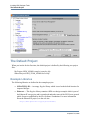
Table 1-1. HTML Button Bar
Button
Description
Hide the navigation pane.
Show the navigation pane.
Highlight current topic in Contents tab.
Display the title page of current document.
Display previous topic.
Display next topic.
Opens the InfoHub help.
Opens a PDF version of the document.
Prints the current topic.
Sends feedback on documentation.
•
Open PDF — opens a PDF (Adobe Acrobat portable document format) version of the
document for printing.
The documents are categorized as follows: What’s New, Quick Reference Index, Manuals,
Application Notes, and Other Documents.
What’s New
This section includes a link to a list of “What’s New” presentations covering the features that
have been introduced in various HDL Designer Series releases, starting from release 2003.1 up
to release 2007.1.
Quick Reference Index
This section provides a link to a list of various quick reference topics.
Manuals
The manuals listed in this section are as follows:
•
10
The HDL Designer Series User Manual describes general user procedures for the HDL
Author and HDL Designer tools.
Start Here Guide, V2008.1
September 18, 2008
Introduction
Documentation
•
The Graphical Editors User Manual describes procedures for using the graphical
symbol, tabular IO, block diagram, IBD view, flow chart and truth table editors.
•
The State Machine Editors User Manual describes procedures for using the state
diagram and algorithmic state machine editors.
•
The DesignPad Text Editor User Guide describes procedures for using the integrated
DesignPad HDL text editor.
•
The DesignChecker User Guide describes procedures for using the integrated
DesignChecker TM static checker.
•
The ModuleWare Reference Guide describes a library of HDL model generators which
can be instantiated in a design and used to implement a large range of standard logic or
arithmetic functions for VHDL or Verilog. Descriptions of each generator in the library
in a HTML version of this manual can be accessed directly from each part in the library.
•
The HDL Designer Series Tcl Reference Manual describes procedures for using the
HDS library contents API and HDS Tcl API commands.
•
The Start Here Guide for the HDL Designer Series (this document) which gives you
introductory information on the HDL Designer Series tools and describes procedures for
invoking them.
Application Notes
The following application notes are available:
•
Designing with Altera’s NIOSII Embedded Processor
•
Designing with Xilinx Embedded Processor
•
Predicting the Output of Finite State Machines
•
PSL Flow
•
Running DesignChecker in Batch Mode
Other Documents
This section includes miscellaneous documents as follows:
•
Enscript Manual Pages
•
GNU Utilities for Comparing and Using Files
•
RCS Manual Pages
•
Version Management using CVS
Start Here Guide, V2008.1
September 18, 2008
11
Introduction
Documentation
Support and Training
This tab provides links to support and training resources, both locally installed and on
SupportNet. This tab comprises of the following sections:
•
Search HDS SupportNet
•
Technical Support and Downloads
•
Tutorials
•
Self-running Demos
•
Contact Us
Search HDS SupportNet
This section allows a natural language search of SupportNet. This powerful search enables you
to enter a complete question, not just keywords. The search on SupportNet covers all HDS
documentation, in addition to technical notes, application notes, and release notes for update
releases and patches.
Technical Support and Downloads
This section provides access to the product microsite to get downloads, product information,
and patches. It also provides a shortcut to signing-up for SupportPro Newsletter, viewing
TechNotes, and viewing AppNotes.
Tutorials
This section provides access to locally installed tutorials which include the following:
12
•
The Interface-Based Design Tutorial is an introduction to interface-based design (IBD)
for users of the HDL Author or HDL Designer tools which uses HDL import, tabular
IO, an IBD view and ModuleWare parts to capture a VHDL or Verilog text design.
Simulation and synthesis design flows are illustrated using the ModelSim and
LeonardoSpectrum tools.
•
The Design Exploration Tutorial is an introduction to the HDL Designer tool. This
tutorial shows how this tool can be used to import an existing VHDL or Verilog text
design, visualize the design using graphical views and export these views in HTML
format.
•
The DesignChecker Tutorial is an introduction to the DesignChecker tool. This tutorial
shows how to configure DesignChecker settings, analyze a design, and investigate the
analysis results.
•
The SystemVerilog for AVM 2.0 and QuestaSim 6.2g and SystemVerilog for AVM 3.0
and QuestaSim 6.3.
Start Here Guide, V2008.1
September 18, 2008
Introduction
Documentation
Self-Running Demos
This section includes the following “How to” demos:
•
DesignChecker Demos
•
Interface-Based Design Demos
Contact Us
This section provides a shortcut to opening a service request, providing feedback on the
documentation, and providing access to the list of worldwide sales offices.
Release Management
This tab includes the Release Notes for the HDL Designer Series which includes information
about new features, the Release Notes for Licensing Mentor Graphics Software and the
Transition Guide for the HDL Designer Series which includes information about updating from
a previous HDL Designer Series release.
Searching Documentation
There are two search tools embedded in the InfoHub:
•
A keyword search of locally installed HTML content.
•
A comprehensive, natural language search of SupportNet that includes all
documentation, release notes, technical notes, and application notes.
The following search methods can be performed through the InfoHub:
•
Searching a Single HTML Document — this takes place by opening a specific HTML
document and running a search through the Search tab in the navigation pane.
•
Searching a Single PDF Document — this takes place by opening a specific PDF
document and running a search through the Acrobat Reader.
•
Searching the Entire HTML Library from a Document — this takes place by
opening any HTML document, selecting the HDS Online Library option in the Search
tab and then running a search.
•
Searching the Entire HTML Library from the InfoHub — this takes place by
opening the InfoHub and running a local search in the banner text box.
•
Searching SupportNet — the SupportNet can be searched through the InfoHub banner
text box, through the Support and Training tab in the InfoHub, or through the Search tab
of an opened HTML document while setting the SupportNet option.
Start Here Guide, V2008.1
September 18, 2008
13
Introduction
Customer Support
The Help button on the right most side of the InfoHub opens an HTML page that provides more
details on the above search methods.
Dialog Box Help
Most of the Help buttons on dialog boxes are linked to single-page mini-PDF files which
provide links to other related dialog box descriptions and a direct link to the corresponding
section in the user manual.
Customer Support
For information about customer support, please choose How to obtain support from the
Support cascade of the Help menu.
If you have a problem with the HDL Designer Series software, you can use the Generate
Support Info from the Support cascade of the Help menu to create a text file containing
information which may help customer support diagnose the problem.
14
Start Here Guide, V2008.1
September 18, 2008
Chapter 2
Invoking HDL Designer Tools
Invoking on Windows . . . . . . . . . . . . . . . . . . . . . . . . . . . . . . . . . . . . . . . . . . . . . . . . . . . . .
Invoking on UNIX or Linux . . . . . . . . . . . . . . . . . . . . . . . . . . . . . . . . . . . . . . . . . . . . . . . .
Command Line Switches. . . . . . . . . . . . . . . . . . . . . . . . . . . . . . . . . . . . . . . . . . . . . . . . . . .
Team Member Mode . . . . . . . . . . . . . . . . . . . . . . . . . . . . . . . . . . . . . . . . . . . . . . . . . . . . . .
HDS Setup Assistant Wizard . . . . . . . . . . . . . . . . . . . . . . . . . . . . . . . . . . . . . . . . . . . . . . .
Starting the Wizard . . . . . . . . . . . . . . . . . . . . . . . . . . . . . . . . . . . . . . . . . . . . . . . . . . . . . . .
Using the HDS Setup Wizard . . . . . . . . . . . . . . . . . . . . . . . . . . . . . . . . . . . . . . . . . . . . . . .
The Default Project . . . . . . . . . . . . . . . . . . . . . . . . . . . . . . . . . . . . . . . . . . . . . . . . . . . . . . .
Example Libraries. . . . . . . . . . . . . . . . . . . . . . . . . . . . . . . . . . . . . . . . . . . . . . . . . . . . . . . .
Shared Libraries . . . . . . . . . . . . . . . . . . . . . . . . . . . . . . . . . . . . . . . . . . . . . . . . . . . . . . . . .
Using the Example Designs . . . . . . . . . . . . . . . . . . . . . . . . . . . . . . . . . . . . . . . . . . . . . . . .
15
16
16
17
17
17
18
26
26
27
28
Invoking on Windows
On Windows, the HDL Designer Series tools are normally invoked from shortcuts in the
Windows Start menu or desktop (which are created during installation):
HDL Author
HDL Designer
These shortcuts invoke the hdldesigner.exe executable with an appropriate switch for the
licensed configuration you have chosen.
You can also double-click over the executable hdldesigner.exe file in the Windows Explorer,
explicitly enter hdldesigner.exe in the Run dialog box from the Start menu or double-click on
the icon for any HDL Designer Series design object. When invoked in this way, the application
attempts to find a valid license and invokes with the configuration supported by that license.
Note
You can also invoke on Windows by double clicking on a recognized HDL Designer
Series file type in the Windows explorer. For example, by clicking on a block diagram or
IBD view file.
Start Here Guide, V2008.1
September 18, 2008
15
Invoking HDL Designer Tools
Invoking on UNIX or Linux
Invoking on UNIX or Linux
When you install HDL Designer Series products on UNIX or Linux systems, invoke scripts are
created for each tool you selected in the install program as shown in the table below. The scripts
and corresponding shortcut links are located in the bin subdirectory of your installation.
The invocation commands are summarized in the following table:
Table 2-1. HDS Invocation Commands
Tool
Invoke Script
Shortcut
HDL Author
HDL Designer
hdl_author
hdl_designer
hdla
hds
For example, you can invoke HDL Author using either of the commands:
<install_dir>/bin/hdl_author
or
<install_dir>/bin/hdla
Note
All required environment variables are automatically set within the invoke script and
need not be explicitly set if you use these scripts to invoke the tools.
Command Line Switches
Command line switches can be used with any of the invocation commands when you invoke a
HDL Designer Series tool from a shell, batch script or Windows shortcut.
Command line switches can be used to run a Tcl command file or to set invoke options. You can
display a full list of supported switches by using the -help switch or opening the Quick
Reference Index from the Help and Manuals tab of the HDS InfoHub. To open the InfoHub,
select Help and Manuals from the Help menu.
The -teamprefsfile (or -teamprefs) and -prefsfile (or -prefs) switches are supported to allow
migration of the preferences from a previous release.
Refer to “Preferences and Resource Files” in the Transition Guide for the HDL Designer Series
for information about migrating preference files.
If errors are encountered when you use a command line switch, messages are sent to standard
output on UNIX but are not reported on Windows unless you pipe the command output to a file.
16
Start Here Guide, V2008.1
September 18, 2008
Invoking HDL Designer Tools
Team Member Mode
Team Member Mode
The HDL Designer Series tools are normally invoked in single-user mode. In this mode, all
preferences, tasks and templates are stored in writable resource files as defined in the “Resource
Files” appendix in the HDL Designer Series User Manual.
Alternatively, you can invoke in team member mode by using the -team_home command line
switch or the HDS_TEAM_HOME environment variable to specify the location of a shared
hds_team resources directory.
You can also set team member mode and the location of hds_team as preferences in the
General tab of the Main Settings dialog box as described in the “User and Team Preferences”
section of the HDL Designer Series User Manual.
In team member mode, the shared team resources are read-only although users with write access
permissions can edit these resources by selecting Team Administrator mode.
The team resources include version management settings, generated HDL file naming rules,
generation properties, file registration, team tasks, team templates, remote simulation directory
location, project synthesis properties and custom code generation scripts.
HDS Setup Assistant Wizard
The HDS Setup Assistant Wizard guides you through the configuration of HDL Designer Series
tool.
Starting the Wizard
The wizard is started when you invoke a HDL Designer Series tool for the first time. If you
choose to cancel the wizard HDS starts with the default examples project, VHDL as the default
language and all the available flows and tools.
If you choose to click Finish before going through the wizard HDS starts with a new project and
library, VHDL as the default language and all the available flows and tools. You can click
Finish at any step to exit the wizard.
You can invoke the wizard at any time by choosing HDS Setup Assistant from the Help menu
in the Design Manager window.
Start Here Guide, V2008.1
September 18, 2008
17
Invoking HDL Designer Tools
HDS Setup Assistant Wizard
Using the HDS Setup Wizard
The left pane of the wizard displays a tree whose nodes represent the settings to be configured.
These include Language, Type of Design, Simulator, Synthesis, Other Flows, Project Setup,
Design Library and Version Management.
The first time the wizard is invoked you have to use the Next button to navigate through the left
pane tree nodes. On moving to a new node the previous one is enabled.
The right pane of the wizard displays a page where you can configure the settings of the selected
node.
18
Start Here Guide, V2008.1
September 18, 2008
Invoking HDL Designer Tools
HDS Setup Assistant Wizard
Language Page
The language page enables you to specify the most frequently used language in creating new
views. You can later change the default language used. Refer to “Main settings” in the HDL
Designer Series User Manual. You can also specify a language for each new view created.
Refer to “Design Content Creation Wizard” in the HDL Designer Series User Manual.
Design Page
You can optionally specify the type of designs you want to create as ASIC or FPGA. If you
choose FPGA you can further specify the FPGA technology libraries as Altera, Xilinx, Actel or
Lattice.
Start Here Guide, V2008.1
September 18, 2008
19
Invoking HDL Designer Tools
HDS Setup Assistant Wizard
The tasks pane is automatically updated according to the design type you specify.
ASIC Default Task Pane
20
FPGA Default Task Pane
Start Here Guide, V2008.1
September 18, 2008
Invoking HDL Designer Tools
HDS Setup Assistant Wizard
Simulator Page
HDS automatically detects the presence of any installed simulators. The simulator page displays
a list of the detected simulators and sets the default.
Alternatively you can specify a new simulator by clicking New Simulator.
Start Here Guide, V2008.1
September 18, 2008
21
Invoking HDL Designer Tools
HDS Setup Assistant Wizard
Synthesis Page
HDS automatically detects the presence of any installed synthesis tools. The synthesis page
displays a list of the detected synthesis tools and sets the default.
Alternatively you can specify a new synthesis tool by clicking New Synthesis Tool.
22
Start Here Guide, V2008.1
September 18, 2008
Invoking HDL Designer Tools
HDS Setup Assistant Wizard
Other Flows Page
The Other Flows page provides you with the option to select the flows you would like to use.
You can add flows and tasks later.
Project Setup Page
The Project Setup page gives you the option to start with a new project. You can alternatively
choose to view one or all of the designs of the examples project.
To start with a new project:
1. Select New project.
2. Do one of the following:
•
Specify the Project name and location.
•
Click Advanced Setup to display the Project Setup Assistant.
Start Here Guide, V2008.1
September 18, 2008
23
Invoking HDL Designer Tools
HDS Setup Assistant Wizard
To start with the examples project:
1. Select examples to view a list of the design libraries included in the project.
2. Select a design library or the whole project to view.
Design Library Page
The Design Library page is active only if you had chosen to create a new project on the Project
Setup page. It gives you the option to create a new library to save your design files.
24
Start Here Guide, V2008.1
September 18, 2008
Invoking HDL Designer Tools
HDS Setup Assistant Wizard
To start with a new design library:
1. Select Yes.
2. Do one of the following:
•
Specify the Design library name and location. The default location is mapped to the
project location specified on the Project setup page.
•
Click Advanced Setup to display the Design Library Setup Assistant.
Version Management Page
You can choose to enable version management. You can also specify the version management
tool settings.
To enable version management:
1. Select Yes to display a dropdown list of the version management interfaces.
2. Select the version management tool.
3. Specify the version management settings if any.
Start Here Guide, V2008.1
September 18, 2008
25
Invoking HDL Designer Tools
The Default Project
The Default Project
When you invoke for the first time, the default project is defined by the following two project
files:
My Project:$HDS_HOME\examples\examples.hdp
Shared Project:$HDS_TEAM_HOME\shared.hdp
Example Libraries
The following libraries are defined in the examples project:
•
SCRATCH_LIB — An empty Regular library which is used as the default location for
imported designs.
•
Ethernet — This Regular library contains a HDL text design example which is part of
the Ethernet IP core project and is reproduced under the terms of the GNU lesser general
public license as published by the Free Software Foundation. For more information
about the Ethernet IP project, see the web site:
http://www.opencores.org/projects/ethmac/
26
Start Here Guide, V2008.1
September 18, 2008
Invoking HDL Designer Tools
The Default Project
The Ethernet design is defined by a mixture of VHDL and Verilog views and includes a
test bench which can be used to simulate the design.
•
Sequencer_vhd and Sequencer_vlg — These Regular libraries contain VHDL and
Verilog versions of the Fibonacci sequencer design which is shown in many of
illustrations used in this manual.
The Sequencer design is also used for the procedures described in the Design
Exploration Tutorial.
•
TIMER_Vhdl and TIMER_Vlog — These Regular libraries contain completed VHDL
and Verilog versions of a design which implements a timer design using block diagrams,
a re-usable component defined by a HDL text view, a hierarchical state machine and
truth table. The examples include a test bench controlled by a flow chart.
•
UART_TXT, UART, UART_V and UART_V2K— These Regular libraries contain
an example of a universal asynchronous receiver transmitter design with a test bench
which can be used to verify the design if a HDL simulator is available on your system.
The UART_TXT library contains a HDL text version of the design described by a
mixture of VHDL and Verilog views and can be edited using any of the HDL Designer
Series tools.
The UART library contains a graphical version of the design described by VHDL views
using block diagrams, IBD views, state machines, truth tables, flow charts and HDL text
views.
The UART_V library contains an alternative graphical version of the design described
by Verilog.
The UART_V2K library contains an alternative graphical version of the design
described by Verilog 2005.
The UART design is described in “UART Example Design” on page 31.
•
tinycache_sv_lib— This library includes a SystemVerilog design.
Shared Libraries
The following libraries are defined in the default shared project:
•
exemplar — A Regular library containing VHDL packages which support the
LeonardoSpectrum synthesis tool.
•
hds_package_library — A Regular library containing VHDL packages which support
automatic type conversion within the HDL Designer Series tools. This library also
contains packages which support the ModuleWare random value based waveform
generator.
Start Here Guide, V2008.1
September 18, 2008
27
Invoking HDL Designer Tools
The Default Project
•
renoir_package_library — This Regular library is provided for compatibility with
older designs which used the type conversion packages. New designs should use the
conversion functions in the hds_package_library.
•
moduleware — This Protected library contains HDL function generators which can be
instantiated as components in block diagram, IBD or HDL text views. The ModuleWare
models are described in the ModuleWare Reference Guide.
•
std — This Protected library contains STANDARD and TEXTIO standard VHDL
packages.
•
ieee — This Protected library contains the IEEE standard VHDL packages which are
recognized by most downstream simulation tools.
•
std_developerskit — This Protected library contains VHDL packages which support
the development of VHDL models using the ModelSim simulation tools.
•
synopsys — This Protected library contains VHDL packages to support the Synopsys
Design Compiler synthesis tool.
•
verilog — This Protected library contains definitions for the standard Verilog types.
The hds_package_library (or renoir_package_library) and exemplar package libraries must be
compiled to make them available for use.
You should add downstream mapping for these libraries to a location where you have write
permission. After compiling these libraries, they should be changed to Protected libraries to
avoid accidental regeneration or recompilation.
The contents of the standard VHDL packages are described in the “VHDL Standard Libraries”
section of the HDL Designer Series User Manual.
Using the Example Designs
The example designs can be opened as read-only reference examples. Windows users typically
have write access to these designs. However, it is recommended that you copy the design to a
suitable directory for user data.
The directories for source data, generated HDL and downstream data can be anywhere on your
file system. Typically, you may use separate subdirectories within the same tree. For example,
the UART libraries are mapped to hds, hdl and work directories beneath a common uart (or
uart_v) directory.
If you want to use the GNU Concurrent Versions System (CVS), the source data must be in a
directory which exactly matches the name of the library. Refer to “Creating a Library Mapping”
in the HDL Designer Series User Manual for more information.
Use the following procedure to make a copy of the example library:
28
Start Here Guide, V2008.1
September 18, 2008
Invoking HDL Designer Tools
The Default Project
1. Set library mapping (including HDL HDS source, and downstream directories to which
you have write permission) for a new empty library.
2. Select the new library and the library you want to copy in the project manager. Choose
Explore Library from the File or popup menu to open both libraries in a new design
explorer window.
3. Select the top level design unit in the example library and drag it over the new library
name with the
mouse button.
4. Choose Copy Special Here from the popup menu which is displayed when you release
the mouse button to display the Copy Special Options dialog box.
5. Select Copy Through Components, Copy to target library and All levels in the
dialog box.
6. Confirm the dialog box.
A complete logical copy of the origin library is made in the target library. All references in the
new library to objects in the original library are updated to reference the new library.
Note that, HDL filenames are derived from the logical names of the HDL text views. (For
example, if you copy the TIMER_Vlog library, the BCDCounter view is copied to a new file
named BCDCounter.v.)
Start Here Guide, V2008.1
September 18, 2008
29
Invoking HDL Designer Tools
The Default Project
You can also copy a library by selecting the library name in the design explorer and choosing
Copy Contents from the popup menu and then using the Paste command to make a physical
copy in the new library.
When you use these commands, all the files in the origin library are copied. (For example, if
you copy the TIMER_Vlog library, the BCDCounter view is copied to a new file named
Timer_BCDCounter.v, preserving the original file name used in the origin library.)
The new library can be browsed, edited, generated, compiled, simulated, animated or
synthesized without any impact on the original examples.
If you want to animate any flow charts and state diagrams in an example design, you should set
Instrument HDL for animation in the properties for the state machine and flow chart and then
regenerate the HDL through components.
30
Start Here Guide, V2008.1
September 18, 2008
Appendix A
UART Example Design
The Universal Asynchronous Receiver Transmitter (UART) design is provided as a mixed
VHDL and Verilog HDL text design and as separate graphical VHDL and Verilog versions to
illustrate the key design creation facilities provided by the HDL Designer Series products.
Overview
The design is a UART which provides serial communications between a CPU (such as an ARM
processor) and a Serial Device. The full specification for the device can be found at the end of
this document.
•
Different baud rates can be set for the transmit/receive clock divider. This can be done
by writing the most significant and least significant divide values into the divmsb and
divlsb registers.
•
Data is transmitted by writing the 8 bit value into the xmitdt register. The interrupt line
(int) goes high when the transmit cycle is completed. The data is placed on the serial out
line (sout) with the appropriate start and stop bits.
•
Serial data is received into the recvdt register. The interrupt line (int) goes high when a
correctly constructed word has been received.
•
Any internal register can also be read by the CPU.
•
A Status Register contains flags to indicate when transmission or receiving is in
progress or completed.
•
The status register and hence the interrupt can be cleared by reading register address 7.
Two graphical versions of the design are provided in the libraries UART (VHDL) and UART_V
(Verilog). Both of these graphical designs are partitioned as follows:
UART
uart_tb (struct - block diagram)
tester (flow - flow chart)
uart_top (struct - block diagram)
clock_divider (flow - flow chart)
cpu_interface (intconx - IBD; struct - block diagram)
data_out_mux (embedded HDL text)
control_operation (fsm - hierarchical state diagram)
serial_interface (struct - block diagram)
convert (embedded flow chart)
zeros (ModuleWare)
status_registers (spec - hand-written HDL)
ser_out_mux (ModuleWare)
Start Here Guide, V2008.1
September 18, 2008
31
UART Example Design
Design Description (uart_top)
xmit_rcv_control (fsm - concurrent state diagram)
address_decode (tt - truth table)
Note
The CPU interface is described by an IBD view but an alternative block diagram view is
also provided.
A third UART_TXT library describes the UART using a mixture of VHDL and Verilog HDL
text views without any graphical views:
UART_TXT
uart_tb (rtl - Verilog text)
tester (rtl - Verilog text)
uart_top (rtl - VHDL text)
clock_divider (rtl - Verilog view)
cpu_interface (rtl - VHDL text)
control_operation (rtl - VHDL text)
serial_interface (rtl - VHDL text)
status_registers (rtl - VHDL text))
xmit_rcv_control (rtl - VHDL text)
address_decode (rtl - VHDL text)
Design Description (uart_top)
The starting point for the design is the top-level block diagram. This diagram describes the toplevel functional blocks of the device. A component symbol can be automatically created from
the block diagram. Alternatively, the symbol can be created first, from the input/output
specification and the top-level block diagram created as an underlying description.
The CPU has the ability to reset the UART and to read to and write from the registers in the
UART. The Serial Device can either be receiving data from the UART or transmitting data to
the UART.
UART Interface
The UART interface is designed for use with an ARM processor and consists of the following
signals:
32
•
data_in[7:0] — This is the 8-bit input data bus which carries the data which the CPU
writes to the UART registers.
•
data_out[7:0] — This is the output data bus which carries the data from the selected
UART register.
•
addr[2:0] — This is the address bus which is connected to the CPU. This signal
indicates which register is being written or read by the CPU.
•
sin — This is the serial input signal from the external serial device. When serial data is
being read, the register rcvdt is loaded with individual bits from this signal.
Start Here Guide, V2008.1
September 18, 2008
UART Example Design
Design Description (uart_top)
•
sout — This is the serial output signal to the external serial device. The contents of
xmitdt register is output one bit at a time.
•
int — This signal indicates that serial data has been transmitted or received successfully
and requests an interrupt from the CPU.
•
cs — This Chip Select signal is asserted low to enable transmit and receive cycles.
•
nrw — notRead/Write. ’0’ indicates a Read operation, ’1’ indicates Write.
•
clk — The main system clock. 50% duty cycle. Typically 100ns clock period.
•
rst — Active low asynchronous reset.
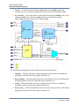
UART Structure
The four top-level blocks are:
•
address_decode — Uses the lowest 3 bits of the CPU address bus to determine which
register is being addressed.
•
clock_divider — Provides a sampling clock for transmitting and receiving serial data.
The baud rate is determined by the two-byte divisor value (divlsb, divmsb) used to
divide down the main system clock.
•
cpu_interface — This block controls whether the UART is transmitting, receiving or
clearing the status flags (and interrupt). It also provides CPU access to the internal
UART register information.
•
serial_interface — Performs the actual transmission and receiving of serial data. It also
stores the status flags and generates the interrupt. This block also provides the
transmit/receive register information to the cpu_interface.
Address Decode
The address_decode block is defined as a truth table. It decodes the last 3 bits of the address bus
(addr) to provide a set of enable signals indicating which register is being addressed:
•
clk_div_en — This is set if either divlsb(0) or divmsb(1) of the clock divider registers
is being addressed.
•
xmitdt_en — Indicates transmit register (xmitdt) is being addressed.
•
ser_if_select — Contains the last two bits of the address bus which are used to select the
register to output onto the ser_if_data bus.
Start Here Guide, V2008.1
September 18, 2008
33
UART Example Design
Design Description (uart_top)
•
clr_int_en — A "pseudo register" which, when read, causes the status flags and
interrupt flag to be cleared.
Clock Divider
The clock_divider is described as a flow chart. The divider can be asynchronously reset
otherwise the divider either loads in the 2-byte divider value or counts clock edges. The
resulting output signal ‘sample’ is a 50% duty cycle divided clock. This is used as the clock for
transmission and receiving operations.
CPU Interface
The cpu_interface is described by an IBD view which performs two operations:
34
•
control_operation — determines which mode of operation the UART is in (transmit,
receive, clearing).
•
data_out_mux — places the clock divider value (div_data) or serial interface register
information (ser_if_data) onto the CPU data_out bus depending on the value of
clk_div_en.
Start Here Guide, V2008.1
September 18, 2008
UART Example Design
Design Description (uart_top)
Control Operation
The register operations of the UART are controlled by the signals nrw and the chip select flow,
cs. The control_operation component is described as a hierarchical state machine which
consists of a top-level state waiting (also the reset state) and two hierarchical states for transmit
(TX) and receive (RX).
The following states can be implied from the UART specification:
•
waiting — No register read or write operations have been requested by the CPU.
•
TX/writing_to_reg — Output enable_write is set. Data is being taken from the
data_out bus and is being written to the register indicated by the address bus (addr).
•
TX/xmitting — Output start_xmit is set. The UART is transmitting data to the serial
output flow (sout). This occurs after the xmitdt register (4) has been written.
•
RX/reading_from_reg — Data is being taken from the register indicated by the address
bus (addr) and is being written to the data_out bus.
•
RX/clearing_flags — Output clear_flags is set. The UART is clearing the status
register (status) and resetting the interrupt flag (int). This occurs after register 7 has
been read.
The outputs from the control_operation component are:
•
enable_write — Indicates that a register should be written; data should be taken from
the input data bus (data_in).
•
start_xmit — Indicates that serial data transmission should commence.
•
clear_flags — Indicates that the internal flags (associated with transmitting and
receiving) should be cleared.
Data Out Mux
•
The data_out_mux is described by an embedded HDL text block. The output placed on
the CPU data_out bus is determined by the clk_div_en signal. If clk_div_en is ’1’, the
clock divider value (div_data) from the clock_divider block is output, otherwise the
serial interface information from the serial_interface block is output.
Serial Interface
The serial_interface block consists of four main functions:
•
xmit_rcv_control — Controls the transmitting and receiving of serial data to/from the
external serial device.
•
status_registers — Stores the transmit and receive status flags, composes the status
byte and produces the interrupt (int).
Start Here Guide, V2008.1
September 18, 2008
35
UART Example Design
Design Description (uart_top)
•
convert — Loads the transmit data from data_out into the xmitdt register and
composes the receive register (recvdt) from the incoming serial data stream (sin).
•
ser_out_mux — places the contents of the transmit data register (xmitdt) or the receive
register (recvdt) or the status byte (status) onto the serial interface data bus
(ser_if_data) depending on the value of ser_if_select.
The following internal signals provide communication between the blocks:
36
•
xmitting — Indicates that data is being transmitted to the serial device and that the
appropriate status bit of the status register should be set.
•
done_xmitting — Indicates that transmission to the serial device has just finished and
that the appropriate status bit of the status register should be set.
•
rcving — Indicates that data is being received from the serial device and that the
appropriate status bit of the status register should be set.
•
done_rcving — Indicates that data has been received from the serial device and that the
appropriate status bit of the status register should be set.
Start Here Guide, V2008.1
September 18, 2008
UART Example Design
Design Description (uart_top)
•
read_bit — Indicates that one bit of data should be loaded into part of the receiving
register (recvdt).
•
rcv_bit_cnt — Indicates the bit position into which the serial data should be read.
•
xmitdt — Contains the data which will be transmitted to the serial device.
Xmit Rcv Control
The UART specification describes, step-by-step, how serial data is transmitted and received.
These operations are performed by two concurrent state machines, one for the transmitting of
data (Xmit), and one for the receiving of data (Rcv). Although both machines run with the
system clock (clk) the transmit and receive baud rate is determined by the divided clock
"sample".
•
Transmit (Xmit)
After register 4 (xmitdt) is written, control_operation sets start_xmit which causes
serial transmission to commence. After sending an initial ’0’ start bit, the transmit clk
(sample) is enabled and the xmitting flag set.
The contents of the xmitdt register is placed on the serial line (sout) one bit at a time on
the rising edge of sample. Once all 8 bits have been transmitted, a ’1’ stop bit is sent, the
done_xmitting is flag set and the sample clock is disabled.
•
Receive (Rcv)
Serial data is received when the serial input flow sin goes low (and remains low for a
specified amount of time). If lock is achieved, the receive clock (sample) is enabled and
the receiving flag set.
The signal read_bit is set/reset for the following 8 rising/falling edges of sample. The
stop bit is skipped, the done_rcving flag is set and the sample clock is disabled.
Status Registers
The status_registers block is described directly in HDL. This block registers the transmit and
receive status flags (xmitting, done_xmitting, rcving, done_rcving) and to compose the 8-bit
status byte from these flags. Once the done flags are set, they remain at ’1’ until cleared. The
interrupt signal (int) is set if the done_xmitting or done_rcving flags are set. The status flag
registers (and hence the status byte and interrupt) are cleared by either the clear_flags signal
from control_operation or by the system reset (rst).
Convert
The convert embedded block is described as a flow chart. This block loads and stores the
xmitdt and recvdt registers. Both registers are cleared by the system reset (rst) asynchronously.
On the system clock edge (clk), if xmitdt_en and enable_write are both set, the transmit
register (xmitdt) is loaded with the value from the CPU on the data_in bus. Otherwise, if
Start Here Guide, V2008.1
September 18, 2008
37
UART Example Design
Test Bench (uart_tb)
read_bit is set, then the current serial input value (sin) is loaded into the appropriate bit of the
receive register (recvdt).
Ser Out Mux
The serial output multiplexer block ser_out_mux consists of an 8-bit constant (constvec)
providing an all zero output vector and a 4-input, 8-bit multiplexer (mux4) implemented by
ModuleWare components. The output ser_if_data is assigned the value of the xmitdt, recvdt
or status registers depending on the value of the ser_if_select signal. ser_if_data is connected
to the data_out_mux in the cpu_interface for output to the CPU data_out bus.
Test Bench (uart_tb)
The design library includes a test bench component, uart_tb. This is a block diagram containing
an instance of the uart itself (uart_top) with all inputs and outputs connected to a tester block
(tester). The tester block is described using a flow chart, which is well-suited to the
procedural/sequential nature of test functions. The tester performs the following test sequence:
•
Initialize inputs and perform system reset
•
Test serial data transmission:
•
38
o
Write "06" into clock divider LSB
o
Write "00" into clock divider MSB
o
Write "5A" into the transmit register (xmitdt)
o
Check interrupt (int) is asserted after serial transmission
o
Clear interrupt (int) by reading register 7
Test serial data receive:
Start Here Guide, V2008.1
September 18, 2008
UART Example Design
Test Bench (uart_tb)
•
o
Place start bit (’0’) onto serial input line (sin)
o
Place serial data "CE" (11001110) onto serial input line (sin) starting with the least
significant bit
o
Place stop bit (’1’) onto serial input line (sin)
o
Clear interrupt (int) by reading register 7
o
Read receive register (rcvdt)
o
Check value in receive register is same as the serial data sent to the UART ("CE")
Test status:
o
Read status register (status)
o
Check all bits are zero
The tester flow chart description also contains a clock generator in the concurrent statements
section and procedures in the process declaration section to perform the uart read and write
functions. The declarations include constants for the system clock period (100ns) and the test
transmit and receive data.
Simulation Results
The simulation results should be similar to those shown overleaf.
Start Here Guide, V2008.1
September 18, 2008
39
UART Example Design
Test Bench (uart_tb)
40
Start Here Guide, V2008.1
September 18, 2008
UART Example Design
UART Specification
UART Specification
UART Registers
The UART contains 6 registers, each 8 bits wide:
0
1
2
3
4
5
6
DIVLSB
DIVMSB
Unused
Unused
XMITDT
RECVDT
STATUS
7
CLRINT
Contains Least Significant bits of Clock Divider
Contains Most Significant bits of Clock Divider
Contains data to be transmitted
Contains received data
Contains UART Status
bit 0
Indicates transmitting in progress
bit 1
Indicates receiving is in progress
bit 2
Indicates transmission is done
bit 3
Indicates receiving is done
When read from, clears the interrupt flag as well
as receive and transmit done flags
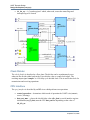
UART Application
cs
data_in(7:0)
data_out(7:0)
CPU
addr(2:0)
nRW
int
UART
sin
sout
SERIAL
DEVICE
rst
clk
o Reset UART
o Read UART registers
o Write UART registers
Start Here Guide, V2008.1
September 18, 2008
o Transmit data
o Receive data
41
UART Example Design
UART Specification
Reading from a UART Register
addr(2:0)
nRW
cs
data_out
•
If cs is low and nRW is low, put the content of the UART register addressed by addr
onto the data_out bus.
•
If the address was 7 (CLRINT) then clear interrupt flag and transmit and receive done
bits in status register.
Writing to a UART Register
addr(2:0)
nRW
cs
data_in
•
If cs is low and nRW is high, save data_in in the UART register addressed by addr.
•
If the address was 4 (XMITDT) then start transmitting content of the xmitdt register to
the serial device.
Transmitting Data
If the last operation from the CPU was write to register number 4 (xmitdt) then start
transmitting content of xmitdt register, one bit at a time.
42
•
Set transmitting bit in the status register to one (bit 0 of status register).
•
Enable the transmit clock.
•
Send start bit (a zero bit half of the duration of the transmit clock).
•
Send content of register number 4 one bit at a time starting with least significant bit first.
Start Here Guide, V2008.1
September 18, 2008
UART Example Design
UART Specification
•
Send stop bit (a one bit).
•
Clear transmitting bit in the status register.
•
Set done transmitting bit in the status register to one (bit 2 of status register).
•
Set interrupt flag to one.
clk
nRW
cs
addr
data_in
start
1
1
stop
sout
xmitting
done_xmitting
int
Receiving Data
•
Wait for falling edge of sin.
•
Wait for half of receive clock (sample) cycle.
•
If sin is still low (start bit), start receiving data, otherwise abort operation and wait for
another falling edge of sin.
•
Set receiving bit in the status register to one (bit 1 of status register).
•
Enable the receive clock.
•
Receive data, one bit at a time starting with least significant bit (including stop bit).
Start Here Guide, V2008.1
September 18, 2008
43
UART Example Design
UART Specification
•
Save received data in register number 5 (recvdt), strip off the stop bit.
•
Clear receiving bit in the status register.
•
Set done receiving bit in the status register to one (bit 3 of status register).
•
Set interrupt flag to one.
clk
start
1
1
stop
sin
rcving
done_rcving
int
44
Start Here Guide, V2008.1
September 18, 2008
Appendix B
Environment Variables
Environment variables are used to locate the license server. There are also a number of
application environment variables which can be used to locate tasks and project files or to
enable specific features and a number of other general purpose variables are recognized if they
are set in your environment.
Licensing Variables:
LM_LICENSE_FILE
MGLS_CONN_TIMEOUT
MGLS_HOME
MGLS_LICENSE_FILE
MGLS_PKGINFO_FILE
HDL Designer Series Variables:
HDS_DEBUGFONTS
HDS_GENRULES_SCRIPT
HDS_HOME
HDS_INSTANCE_LIMIT
HDS_KANJI_DIALOGS
HDS_KEEPFILE
HDS_KEYS
HDS_LIB_MIGRATION
HDS_LIBS
HDS_LOG_TIMEOUT
HDS_MAX_ILOG_AREA
HDS_NEW_PROJECT_DIR
HDS_PLUGINS
HDS_PORT
HDS_PREFS
HDS_PROJECT_DIR
HDS_REPOSITORY
HDS_SIGNAL_LIMIT
HDS_TCL
HDS_TEAM_HOME
HDS_TEAM_VER
HDS_TEAMPREFS
HDS_USER_HOME
HDS_USER_VER
General Purpose Variables:
CDS_INST_DIR
CVE_HOME
CVSROOT
EDITOR
EXEMPLAR
LD_LIBRARY_PATH
MGC_HOME
Start Here Guide, V2008.1
September 18, 2008
MGC_LOCATION_MAP
MGC_WD
MODELSIM
SPYGLASS_HOME
SSDIR
TZ
45
Environment Variables
List of Variables
List of Variables
CDS_INST_DIR
Specifies a pathname to the location of a Cadence software tree. This variable can be used to
specify the installation directory containing the Cadence NC-Sim simulator executable.
CVE_HOME
Specifies a pathname to the location of the Seamless CVE software. This location is required for
library mapping when you instantiate a CVE model as an external HDL model in a block
diagram.
CVSROOT
Specifies the pathname of a directory used as the repository for CVS source control objects (for
example when setting up a CVS modules file outside the tool). It is set internally to the location
specified in the version management options.
EDITOR
Specifies the default editor for text files on UNIX or Linux systems. It is usually set to the name
of the editor and located using the default search path. This editor can be used for editing or
viewing HDL text views files if you set XTerm with Editor as the text editor command in your
preferences.
EXEMPLAR
Specifies a pathname to the installation directory containing the LeonardoSpectrum synthesis
tools. This variable is not required when LeonardoSpectrum is invoked from a HDL Designer
Series tool and may cause problems if set to an out-of-date location.
HDS_DEBUGFONTS
When set to any value, font mapping information is sent to standard error output.
HDS_GENRULES_SCRIPT
Specifies the pathname to a Tcl script used to expand view properties variables.
HDS_HOME
Specifies a pathname to the HDL Designer Series installation directory. This variable is used
internally to locate application resources in the installation directory.
HDS_INSTANCE_LIMIT
Specifies a default integer limit to the number of instance declarations found in a HDL file by the
HDL parser. The limit can be overidden by specifying a value in the Checks tab of the Main
Settings dialog box.
HDS_KANJI_DIALOGS
When set to a non integer value, such as ‘ON’, enables a font which allows the entry of Kanji
characters in the Comments dialog box.
46
Start Here Guide, V2008.1
September 18, 2008
Environment Variables
List of Variables
Note
Setting the HDS_KANJI_DIALOGS to any non-integer value prevents the text from
getting cut-off.
HDS_KEEPFILE
When set to any non zero value, the temporary list file created during HDL compilation is not
deleted when the compilation window is closed.
HDS_KEYS
Specifies a pathname to an alternative location for the hds.keys file. If not set, a keys file in the
wo is used (if it exists) or a keys file in your user directory. If not found in these locations, the
default hds.keys file in the resources/misc installation subdirectory is used. This variable is
ignored if the -keysfile command line switch is used to specify a keys file.
HDS_LIB_MIGRATION
When set to any value, the library migration wizard is available from the background popup
menu in the project manager. This wizard can be used to migrate libraries created using pre2003.1 releases to the hierarchical data model (HDM).
HDS_LIBS
Specifies the full pathname to the current user project file (hds.hdp). This variable is overridden
if the location is specified using the -hdpfile command line switch.
HDS_LOG_TIMEOUT
Specifies a timeout period in seconds for the log displayer process. This variable is not usually
required but can be used (set to a low value such as 5) to overcome a problem on Windows
workstations which prevents the simulator from being re-invoked.
HDS_MAX_ILOG_AREA
Specifies the maximum image area in pixels which is used when exporting a diagram as HTML.
If not set, defaults to 5000000 pixels square.
HDS_NEW_PROJECT_DIR
Specifies the pathname to the default location used to contain the folder for a new project.
HDS_PLUGINS
Specifies a list of pathnames to the location of directories containing "plug-in" drivers for
external tools. Multiple locations can be specified by separating the pathname strings by a colon
(on UNIX or Linux) or semi-colon (on a Windows PC). When set, a plug-in one of the specified
directories takes priority over a standard plug-in with the same name in the
HDS_HOME\resources\downstream\drivers directory.
HDS_PORT
Specifies an integer number for the IPC (inter-process communication) port used to
communicate with an external tool. This variable should be set when you want to setup two-way
communication between the HDL Designer Series source objects and HDL code displayed using
a server application such as the GNU Emacs editor. Typically, HDS_PORT should be set to
Start Here Guide, V2008.1
September 18, 2008
47
Environment Variables
List of Variables
<localhost>:<portnumber> where localhost is the name of your workstation and portnumber is
an unused IPC port number or TCP service name allocated by your system administrator.
HDS_PREFS
Specifies the full pathname to a pre-2003.1 user preferences file (.hdsPrefsV where V is the
software version number) which you want to be migrated to the latest release. This variable is
overridden if the -prefsfile command line switch is used to specify the preferences file.
HDS_PROJECT_DIR
This variable is set internally to the location containing the folder for the active project. It can be
used in the library mapping wizard to specify a root directory relative to the active project folder.
HDS_REPOSITORY
Specifies the pathname of a directory used as the repository for RCS source control objects. If
this variable is set and no location is already set in your preferences, it is used as the RCS
repository.
HDS_SIGNAL_LIMIT
Specifies a default integer limit to the number of signal declarations found in a HDL file by the
HDL parser. The limit can be overidden by specifying a value in the Checks tab of the Main
Settings dialog box.
HDS_TCL
Specifies the pathname of a Tcl script that is sourced at start up immediately before any file
specified with the -do switch.
HDS_TEAM_HOME
Specifies a pathname to the location of the hds_team directory and sets team member mode. The
hds_team directory contains the default shared resources project file (shared.hdp) and versioned
files for team preferences, tasks and templates. The default location is in the user directory or the
location from which team preferences for a previous release have been read. This variable is
ignored in single-user mode or if an existing location is specified using the -team_home
command line switch.
HDS_TEAM_VER
This variable is automatically derived at run time to specify the versioned directory containing
team preference, task and template files for the current release. For example:
$HDS_TEAM_HOME/hds_team/v2003
HDS_TEAMPREFS
Specifies the full pathname to a pre-2003.1 team preferences file (.hdsTeamPrefsV where V is the
software version number) which you want to be migrated to the latest release. This variable is
overridden if the -teamprefsfile command line switch is used to specify an old team preferences
file.
HDS_USER_HOME
Specifies the location of the hds_user directory containing the user resource files (including
versioned files for user preferences, tasks and templates). The default location is in the user
48
Start Here Guide, V2008.1
September 18, 2008
Environment Variables
List of Variables
directory or in the location from which user preferences for a previous release have been read.
This variable is ignored if an existing location is specified using the -user_home command line
switch.
Note
If the user directory contains special characters, such as ü or ä, you should change the
hds_user directory to another directory that does not contain any special characters.
HDS_USER_VER
This variable is automatically derived at run time to specify the versioned directory containing
user preference, task and template files for the current release. For example:
$HDS_USER_HOME/hds_user/v2004.
LD_LIBRARY_PATH
Specifies the location of directories containing some display libraries which are required on
UNIX or Linux systems.
LM_LICENSE_FILE
Specifies the location of the licensing file. Typically specified by a port number and host name in
the form: <portnumber>@hostname An evaluation license may be located by specifying the
pathname. Multiple locations can be separated by a : (colon) on UNIX or Linux or by a ; (semicolon) on Windows.
MGC_HOME
Specifies a pathname to the location of a Mentor Graphics software tree. This variable is not
required but may be useful if you want to use other Mentor Graphics tools. (For example, if you
want to read a default location map file in the MGC_HOME tree.)
MGC_LOCATION_MAP
Specifies a pathname to a Mentor Graphics location map file. When set, any valid location map
entry can be used to set a library mapping pathname.
MGC_WD
Specifies a pathname to the location of the working directory used by the tools installed in a
Mentor Graphics software tree. It is not used by the HDL Designer Series tools. However, if you
use the ModelSim downstream tools, the vmap utility checks for an existing modelsim.ini file in
this directory and if it exists, references this file for library mapping.
MGLS_CONN_TIMEOUT
Specifies a delay (in seconds) to wait for the license server to respond. The default is 10 but it
can be increased to reduce the risk of timeout due to slow response from the server.
MGLS_HOME
Specifies a pathname to the location of the Mentor Graphics licensing system on a UNIX or
Linux system.
Start Here Guide, V2008.1
September 18, 2008
49
Environment Variables
Setting Environment Variables
MGLS_LICENSE_FILE
Specifies the location of an alternative license file that is used in preference to the
LM_LICENSE_FILE variable for users who are already using other Mentor Graphics products.
MGLS_PKGINFO_FILE
Specifies a pathname to a directory containing an alternative mgc.pkginfo file which may be
required in an existing UNIX MGC licensing environment. If this variable is not set, HDS uses
the mgc.pkginfo file in the bin subdirectory of the HDS installation.
MODELSIM
Specifies a pathname to the initialization file (modelsim.ini) used by the ModelSim compiler and
simulator on UNIX or Linux systems. HDL Designer Series tools create this file in the compiled
library directory and the variable does not need to be set unless you invoke ModelSim
independently.
SPYGLASS_HOME
Specifies a pathname to the location of a SpyGlass software tree containing the Atrenta SpyGlass
RTL rule checker.
SSDIR
Specifies a pathname to the srcsafe.ini file in a Microsoft or Mainsoft Visual SourceSafe version
control system.
TZ
Specifies the time zone. Usually set to an alphabetic time zone name. For example: GB
Setting Environment Variables
An environment variable is a shell-level variable that lets you communicate with your program
and to set its internal states as it is executing. The names of these variables and the values that
you assign to them are case sensitive.
Environment variables can be set on UNIX systems using the set or setenv shell commands. For
example:
setenv HDS_REPOSITORY /usr1/hds_repository_directory
User and system environment variables can be set on Windows systems using the Advanced tab
of the System dialog box which can be accessed from the Windows Control Panel. To enter a
new user variable, check that no existing variable is selected and enter the new variable name
and value. For example:
Variable: HDS_REPOSITORY
Value: C:\Designs\hds_repository_directory
50
Start Here Guide, V2008.1
September 18, 2008
Environment Variables
Setting Environment Variables
Note
Take care that an existing system variable is not selected when using the dialog box. New
user variables are available when you apply the dialog box but accidental changes to a
system variable may cause problems later when rebooting your machine.
Start Here Guide, V2008.1
September 18, 2008
51
Environment Variables
Setting Environment Variables
52
Start Here Guide, V2008.1
September 18, 2008
A B C D E F G H I J K L M N O P Q R S T U V W X Y Z
Index
Index
—C—
Command line switches, 16
list of switches
see the Quick Reference Index
—D—
DesignPad, 6
—E—
Environment variables
CDS_INST_DIR, 46
CVE_HOME, 46
CVSROOT, 46
EDITOR, 46
EXEMPLAR, 46
HDS_DEBUGFONTS, 46
HDS_GENRULES_SCRIPT, 46
HDS_HOME, 46
HDS_INSTANCE_LIMIT, 46
HDS_KANJI_DIALOGS, 46
HDS_KEEPFILE, 47
HDS_KEYS, 47
HDS_LIB_MIGRATION, 47
HDS_LIBS, 47
HDS_LOG_TIMEOUT, 47
HDS_MAX_ILOG_AREA, 47
HDS_NEW_PROJECT_DIR, 47
HDS_PLUGINS, 47
HDS_PORT, 47
HDS_PREFS, 48
HDS_PROJECT_DIR, 48
HDS_REPOSITORY, 48
HDS_SIGNAL_LIMIT, 48
HDS_TCL, 48
HDS_TEAM_HOME, 17, 48
HDS_TEAM_VER, 48
HDS_TEAMPREFS, 48
HDS_USER_HOME, 48
HDS_USER_VER, 49
LD_LIBRARY_PATH, 49
Start Here Guide, V2008.1
September 18, 2008
LM_LICENSE_FILE, 49
MGC_HOME, 49
MGC_LOCATION_MAP, 49
MGC_WD, 49
MGLS_CONN_TIMEOUT, 49
MGLS_HOME, 49
MGLS_LICENSE_FILE, 50
MGLS_PKGINFO_FILE, 50
MODELSIM, 50
setting, 50
SPYGLASS_HOME, 50
SSDIR, 50
TZ, 50
—H—
HDL Author, 5
invoking, 15
HDL Designer, 7
invoking, 15
HDL Designer Series, 5
invoking, 15
HDL2Graphics, 7
—L—
Library
Ethernet, 26
exemplar, 27
hds_package_library, 27
ieee, 28
moduleware, 28
renoir_package_library, 28
SCRATCH_LIB, 26
Sequencer_vhd, 27
Sequencer_vlg, 27
std, 28
std_developerskit, 28
synopsys, 28
TIMER_Vhdl, 27
TIMER_Vlog, 27
UART, 27
53
A B C D E F G H I J K L M N O P Q R S T U V W X Y Z
UART_TXT, 27
UART_V, 27
verilog, 28
—M—
ModuleWare, 7
—O—
Online help, 14
—P—
Product features, 5
Project
example, 26
shared, 27
—Q—
Quick Reference Index, 10
—U—
UART
address_decode, 33
clock_divider, 33, 34
control_operation, 35
convert, 37
cpu_interface, 33, 34
data_out_mux, 35
interface, 32
overview, 31
ser_out_mux, 38
serial_interface, 33, 35
simulation results, 39
specification, 41
status_registers, 37
test bench, 38
tester, 38
top-level block diagram, 32
xmit rcv control, 37
54
Start Here Guide, V2008.1
September 18, 2008
End-User License Agreement
The latest version of the End-User License Agreement is available on-line at:
www.mentor.com/terms_conditions/enduser.cfm
IMPORTANT INFORMATION
USE OF THIS SOFTWARE IS SUBJECT TO LICENSE RESTRICTIONS. CAREFULLY READ THIS
LICENSE AGREEMENT BEFORE USING THE SOFTWARE. USE OF SOFTWARE INDICATES YOUR
COMPLETE AND UNCONDITIONAL ACCEPTANCE OF THE TERMS AND CONDITIONS SET FORTH
IN THIS AGREEMENT. ANY ADDITIONAL OR DIFFERENT PURCHASE ORDER TERMS AND
CONDITIONS SHALL NOT APPLY.
END-USER LICENSE AGREEMENT (“Agreement”)
This is a legal agreement concerning the use of Software between you, the end user, as an authorized
representative of the company acquiring the license, and Mentor Graphics Corporation and Mentor Graphics
(Ireland) Limited acting directly or through their subsidiaries (collectively “Mentor Graphics”). Except for license
agreements related to the subject matter of this license agreement which are physically signed by you and an
authorized representative of Mentor Graphics, this Agreement and the applicable quotation contain the parties'
entire understanding relating to the subject matter and supersede all prior or contemporaneous agreements. If you
do not agree to these terms and conditions, promptly return or, if received electronically, certify destruction of
Software and all accompanying items within five days after receipt of Software and receive a full refund of any
license fee paid.
1.
GRANT OF LICENSE. The software programs, including any updates, modifications, revisions, copies, documentation
and design data (“Software”), are copyrighted, trade secret and confidential information of Mentor Graphics or its
licensors who maintain exclusive title to all Software and retain all rights not expressly granted by this Agreement.
Mentor Graphics grants to you, subject to payment of appropriate license fees, a nontransferable, nonexclusive license to
use Software solely: (a) in machine-readable, object-code form; (b) for your internal business purposes; (c) for the license
term; and (d) on the computer hardware and at the site authorized by Mentor Graphics. A site is restricted to a one-half
mile (800 meter) radius. Mentor Graphics’ standard policies and programs, which vary depending on Software, license
fees paid or services purchased, apply to the following: (a) relocation of Software; (b) use of Software, which may be
limited, for example, to execution of a single session by a single user on the authorized hardware or for a restricted period
of time (such limitations may be technically implemented through the use of authorization codes or similar devices); and
(c) support services provided, including eligibility to receive telephone support, updates, modifications, and revisions.
2.
EMBEDDED SOFTWARE. If you purchased a license to use embedded software development (“ESD”) Software, if
applicable, Mentor Graphics grants to you a nontransferable, nonexclusive license to reproduce and distribute executable
files created using ESD compilers, including the ESD run-time libraries distributed with ESD C and C++ compiler
Software that are linked into a composite program as an integral part of your compiled computer program, provided that
you distribute these files only in conjunction with your compiled computer program. Mentor Graphics does NOT grant
you any right to duplicate, incorporate or embed copies of Mentor Graphics' real-time operating systems or other
embedded software products into your products or applications without first signing or otherwise agreeing to a separate
agreement with Mentor Graphics for such purpose.
3.
BETA CODE. Software may contain code for experimental testing and evaluation (“Beta Code”), which may not be used
without Mentor Graphics’ explicit authorization. Upon Mentor Graphics’ authorization, Mentor Graphics grants to you a
temporary, nontransferable, nonexclusive license for experimental use to test and evaluate the Beta Code without charge
for a limited period of time specified by Mentor Graphics. This grant and your use of the Beta Code shall not be construed
as marketing or offering to sell a license to the Beta Code, which Mentor Graphics may choose not to release
commercially in any form. If Mentor Graphics authorizes you to use the Beta Code, you agree to evaluate and test the
Beta Code under normal conditions as directed by Mentor Graphics. You will contact Mentor Graphics periodically
during your use of the Beta Code to discuss any malfunctions or suggested improvements. Upon completion of your
evaluation and testing, you will send to Mentor Graphics a written evaluation of the Beta Code, including its strengths,
weaknesses and recommended improvements. You agree that any written evaluations and all inventions, product
improvements, modifications or developments that Mentor Graphics conceived or made during or subsequent to this
Agreement, including those based partly or wholly on your feedback, will be the exclusive property of Mentor Graphics.
Mentor Graphics will have exclusive rights, title and interest in all such property. The provisions of this section 3 shall
survive the termination or expiration of this Agreement.
4.
RESTRICTIONS ON USE. You may copy Software only as reasonably necessary to support the authorized use. Each
copy must include all notices and legends embedded in Software and affixed to its medium and container as received from
Mentor Graphics. All copies shall remain the property of Mentor Graphics or its licensors. You shall maintain a record of
the number and primary location of all copies of Software, including copies merged with other software, and shall make
those records available to Mentor Graphics upon request. You shall not make Software available in any form to any
person other than employees and on-site contractors, excluding Mentor Graphics' competitors, whose job performance
requires access and who are under obligations of confidentiality. You shall take appropriate action to protect the
confidentiality of Software and ensure that any person permitted access to Software does not disclose it or use it except as
permitted by this Agreement. Except as otherwise permitted for purposes of interoperability as specified by applicable
and mandatory local law, you shall not reverse-assemble, reverse-compile, reverse-engineer or in any way derive from
Software any source code. You may not sublicense, assign or otherwise transfer Software, this Agreement or the rights
under it, whether by operation of law or otherwise (“attempted transfer”), without Mentor Graphics’ prior written consent
and payment of Mentor Graphics’ then-current applicable transfer charges. Any attempted transfer without Mentor
Graphics' prior written consent shall be a material breach of this Agreement and may, at Mentor Graphics' option, result in
the immediate termination of the Agreement and licenses granted under this Agreement. The terms of this Agreement,
including without limitation, the licensing and assignment provisions shall be binding upon your successors in interest
and assigns. The provisions of this section 4 shall survive the termination or expiration of this Agreement.
5.
LIMITED WARRANTY.
5.1. Mentor Graphics warrants that during the warranty period Software, when properly installed, will substantially
conform to the functional specifications set forth in the applicable user manual. Mentor Graphics does not warrant
that Software will meet your requirements or that operation of Software will be uninterrupted or error free. The
warranty period is 90 days starting on the 15th day after delivery or upon installation, whichever first occurs. You
must notify Mentor Graphics in writing of any nonconformity within the warranty period. This warranty shall not be
valid if Software has been subject to misuse, unauthorized modification or improper installation. MENTOR
GRAPHICS' ENTIRE LIABILITY AND YOUR EXCLUSIVE REMEDY SHALL BE, AT MENTOR GRAPHICS'
OPTION, EITHER (A) REFUND OF THE PRICE PAID UPON RETURN OF SOFTWARE TO MENTOR
GRAPHICS OR (B) MODIFICATION OR REPLACEMENT OF SOFTWARE THAT DOES NOT MEET THIS
LIMITED WARRANTY, PROVIDED YOU HAVE OTHERWISE COMPLIED WITH THIS AGREEMENT.
MENTOR GRAPHICS MAKES NO WARRANTIES WITH RESPECT TO: (A) SERVICES; (B) SOFTWARE
WHICH IS LICENSED TO YOU FOR A LIMITED TERM OR LICENSED AT NO COST; OR
(C) EXPERIMENTAL BETA CODE; ALL OF WHICH ARE PROVIDED “AS IS.”
5.2. THE WARRANTIES SET FORTH IN THIS SECTION 5 ARE EXCLUSIVE. NEITHER MENTOR GRAPHICS
NOR ITS LICENSORS MAKE ANY OTHER WARRANTIES, EXPRESS, IMPLIED OR STATUTORY, WITH
RESPECT TO SOFTWARE OR OTHER MATERIAL PROVIDED UNDER THIS AGREEMENT. MENTOR
GRAPHICS AND ITS LICENSORS SPECIFICALLY DISCLAIM ALL IMPLIED WARRANTIES OF
MERCHANTABILITY AND FITNESS FOR A PARTICULAR PURPOSE AND NON-INFRINGEMENT OF
INTELLECTUAL PROPERTY.
6.
LIMITATION OF LIABILITY. EXCEPT WHERE THIS EXCLUSION OR RESTRICTION OF LIABILITY
WOULD BE VOID OR INEFFECTIVE UNDER APPLICABLE LAW, IN NO EVENT SHALL MENTOR GRAPHICS
OR ITS LICENSORS BE LIABLE FOR INDIRECT, SPECIAL, INCIDENTAL, OR CONSEQUENTIAL DAMAGES
(INCLUDING LOST PROFITS OR SAVINGS) WHETHER BASED ON CONTRACT, TORT OR ANY OTHER
LEGAL THEORY, EVEN IF MENTOR GRAPHICS OR ITS LICENSORS HAVE BEEN ADVISED OF THE
POSSIBILITY OF SUCH DAMAGES. IN NO EVENT SHALL MENTOR GRAPHICS' OR ITS LICENSORS'
LIABILITY UNDER THIS AGREEMENT EXCEED THE AMOUNT PAID BY YOU FOR THE SOFTWARE OR
SERVICE GIVING RISE TO THE CLAIM. IN THE CASE WHERE NO AMOUNT WAS PAID, MENTOR
GRAPHICS AND ITS LICENSORS SHALL HAVE NO LIABILITY FOR ANY DAMAGES WHATSOEVER. THE
PROVISIONS OF THIS SECTION 6 SHALL SURVIVE THE EXPIRATION OR TERMINATION OF THIS
AGREEMENT.
7.
LIFE ENDANGERING ACTIVITIES. NEITHER MENTOR GRAPHICS NOR ITS LICENSORS SHALL BE
LIABLE FOR ANY DAMAGES RESULTING FROM OR IN CONNECTION WITH THE USE OF SOFTWARE IN
ANY APPLICATION WHERE THE FAILURE OR INACCURACY OF THE SOFTWARE MIGHT RESULT IN
DEATH OR PERSONAL INJURY. THE PROVISIONS OF THIS SECTION 7 SHALL SURVIVE THE
EXPIRATION OR TERMINATION OF THIS AGREEMENT.
8.
INDEMNIFICATION. YOU AGREE TO INDEMNIFY AND HOLD HARMLESS MENTOR GRAPHICS AND ITS
LICENSORS FROM ANY CLAIMS, LOSS, COST, DAMAGE, EXPENSE, OR LIABILITY, INCLUDING
ATTORNEYS' FEES, ARISING OUT OF OR IN CONNECTION WITH YOUR USE OF SOFTWARE AS
DESCRIBED IN SECTION 7. THE PROVISIONS OF THIS SECTION 8 SHALL SURVIVE THE EXPIRATION OR
TERMINATION OF THIS AGREEMENT.
9.
INFRINGEMENT.
9.1. Mentor Graphics will defend or settle, at its option and expense, any action brought against you alleging that
Software infringes a patent or copyright or misappropriates a trade secret in the United States, Canada, Japan, or
member state of the European Patent Office. Mentor Graphics will pay any costs and damages finally awarded
against you that are attributable to the infringement action. You understand and agree that as conditions to Mentor
Graphics' obligations under this section you must: (a) notify Mentor Graphics promptly in writing of the action;
(b) provide Mentor Graphics all reasonable information and assistance to defend or settle the action; and (c) grant
Mentor Graphics sole authority and control of the defense or settlement of the action.
9.2. If an infringement claim is made, Mentor Graphics may, at its option and expense: (a) replace or modify Software so
that it becomes noninfringing; (b) procure for you the right to continue using Software; or (c) require the return of
Software and refund to you any license fee paid, less a reasonable allowance for use.
9.3. Mentor Graphics has no liability to you if infringement is based upon: (a) the combination of Software with any
product not furnished by Mentor Graphics; (b) the modification of Software other than by Mentor Graphics; (c) the
use of other than a current unaltered release of Software; (d) the use of Software as part of an infringing process; (e) a
product that you make, use or sell; (f) any Beta Code contained in Software; (g) any Software provided by Mentor
Graphics’ licensors who do not provide such indemnification to Mentor Graphics’ customers; or (h) infringement by
you that is deemed willful. In the case of (h) you shall reimburse Mentor Graphics for its attorney fees and other costs
related to the action upon a final judgment.
9.4. THIS SECTION IS SUBJECT TO SECTION 6 ABOVE AND STATES THE ENTIRE LIABILITY OF MENTOR
GRAPHICS AND ITS LICENSORS AND YOUR SOLE AND EXCLUSIVE REMEDY WITH RESPECT TO
ANY ALLEGED PATENT OR COPYRIGHT INFRINGEMENT OR TRADE SECRET MISAPPROPRIATION
BY ANY SOFTWARE LICENSED UNDER THIS AGREEMENT.
10. TERM. This Agreement remains effective until expiration or termination. This Agreement will immediately terminate
upon notice if you exceed the scope of license granted or otherwise fail to comply with the provisions of Sections 1, 2, or
4. For any other material breach under this Agreement, Mentor Graphics may terminate this Agreement upon 30 days
written notice if you are in material breach and fail to cure such breach within the 30 day notice period. If Software was
provided for limited term use, this Agreement will automatically expire at the end of the authorized term. Upon any
termination or expiration, you agree to cease all use of Software and return it to Mentor Graphics or certify deletion and
destruction of Software, including all copies, to Mentor Graphics’ reasonable satisfaction.
11. EXPORT. Software is subject to regulation by local laws and United States government agencies, which prohibit export
or diversion of certain products, information about the products, and direct products of the products to certain countries
and certain persons. You agree that you will not export any Software or direct product of Software in any manner without
first obtaining all necessary approval from appropriate local and United States government agencies.
12. RESTRICTED RIGHTS NOTICE. Software was developed entirely at private expense and is commercial computer
software provided with RESTRICTED RIGHTS. Use, duplication or disclosure by the U.S. Government or a U.S.
Government subcontractor is subject to the restrictions set forth in the license agreement under which Software was
obtained pursuant to DFARS 227.7202-3(a) or as set forth in subparagraphs (c)(1) and (2) of the Commercial Computer
Software - Restricted Rights clause at FAR 52.227-19, as applicable. Contractor/manufacturer is Mentor Graphics
Corporation, 8005 SW Boeckman Road, Wilsonville, Oregon 97070-7777 USA.
13. THIRD PARTY BENEFICIARY. For any Software under this Agreement licensed by Mentor Graphics from Microsoft
or other licensors, Microsoft or the applicable licensor is a third party beneficiary of this Agreement with the right to
enforce the obligations set forth herein.
14. AUDIT RIGHTS. You will monitor access to, location and use of Software. With reasonable prior notice and during
your normal business hours, Mentor Graphics shall have the right to review your software monitoring system and
reasonably relevant records to confirm your compliance with the terms of this Agreement, an addendum to this
Agreement or U.S. or other local export laws. Such review may include FLEXlm or FLEXnet report log files that you
shall capture and provide at Mentor Graphics’ request. Mentor Graphics shall treat as confidential information all of your
information gained as a result of any request or review and shall only use or disclose such information as required by law
or to enforce its rights under this Agreement or addendum to this Agreement. The provisions of this section 14 shall
survive the expiration or termination of this Agreement.
15. CONTROLLING LAW, JURISDICTION AND DISPUTE RESOLUTION. THIS AGREEMENT SHALL BE
GOVERNED BY AND CONSTRUED UNDER THE LAWS OF THE STATE OF OREGON, USA, IF YOU ARE
LOCATED IN NORTH OR SOUTH AMERICA, AND THE LAWS OF IRELAND IF YOU ARE LOCATED
OUTSIDE OF NORTH OR SOUTH AMERICA. All disputes arising out of or in relation to this Agreement shall be
submitted to the exclusive jurisdiction of Portland, Oregon when the laws of Oregon apply, or Dublin, Ireland when the
laws of Ireland apply. Notwithstanding the foregoing, all disputes in Asia (except for Japan) arising out of or in relation to
this Agreement shall be resolved by arbitration in Singapore before a single arbitrator to be appointed by the Chairman of
the Singapore International Arbitration Centre (“SIAC”) to be conducted in the English language, in accordance with the
Arbitration Rules of the SIAC in effect at the time of the dispute, which rules are deemed to be incorporated by reference
in this section 15. This section shall not restrict Mentor Graphics’ right to bring an action against you in the jurisdiction
where your place of business is located. The United Nations Convention on Contracts for the International Sale of Goods
does not apply to this Agreement.
16. SEVERABILITY. If any provision of this Agreement is held by a court of competent jurisdiction to be void, invalid,
unenforceable or illegal, such provision shall be severed from this Agreement and the remaining provisions will remain in
full force and effect.
17. PAYMENT TERMS AND MISCELLANEOUS. You will pay amounts invoiced, in the currency specified on the
applicable invoice, within 30 days from the date of such invoice. Any past due invoices will be subject to the imposition
of interest charges in the amount of one and one-half percent per month or the applicable legal rate currently in effect,
whichever is lower. Some Software may contain code distributed under a third party license agreement that may provide
additional rights to you. Please see the applicable Software documentation for details. This Agreement may only be
modified in writing by authorized representatives of the parties. Waiver of terms or excuse of breach must be in writing
and shall not constitute subsequent consent, waiver or excuse.
Rev. 060210, Part No. 227900