1
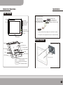
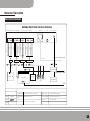
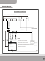
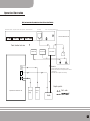
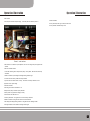
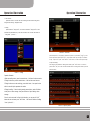
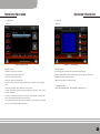
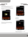
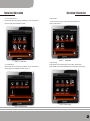
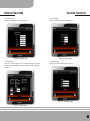
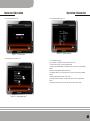
Operation Manual
Before operate our product, please read the manual carefully.
Keep the manual in good condition, for reference later.
波创
BC2- D10E/BC2- D07E
Digital Smart Home Touch Panel
www.18bc.com
Service hotline:0755-86368966
Shenzhen Bochuang Hi-Tech Co.,Ltd.
Preface
Digital smart home Touch panel is based on community smart home system
solution, combine multiple smart home system in the community together by the
community server and community application software, centralized management
and share the resources. Take advantage of the advanced computer techniques,
embedded system techniques, networking communication techniques, home
appliance techniques,RF control techniques, combine sub-system of home life
together. Through the general control, not only realize the community security
monitoring, but also combine home smart control, information and consuming
services together, make the home life more confortable, safer and effective,
provide smart life space to the residents. As the central product of smart home
system, didital smart home Touch panel integrate smart management and video
intercom, media amusement together. It is the perfect combination of modern
hi-tech and smart life and leads the trend of global smart home life.
01
Catalogue
1 Video intercom
18
5.3 timing control
31
1.1 calling
18
5.4 combination control
33
1.2 call record
20
5.5 temperature control
35
1.3 monitoring
21
1.4 management centre
21
6.1 user setting
37
2 Security
22
6.2 engineering setting
46
3 Multi-media
23
6.3 system status
62
3.1 digital frame
23
6.4 help
64
3.2 audio play
24
3.3 video play
24
7.1 telephone long-distance control
65
3.4 photo-taking and message-leaving
25
7.2 networking long-distance control
66
6 system setting
7 long-distance setting and control
37
65
4 community information
26
8 management centre
75
5 home appliance control
27
9 Appendix
76
5.1 scene control
27
10 After sales services
79
5.2 single control
29
03
Product Introduction
1.10.1/7.0"colorful LCD screen
2.Touch screen operation
3.Digital video intercom, no need networking devices
4.Home RF smart control
5.Based on TCP/IP security alarm, alarm linkage, snapshot image
6.Browse website, community service, on-line shopping
7.Home appliance, lighting long-distance control
8.Web-browsing
9.Home appliance, lighting control, scene control, timing control,
temperature control, linkage control
10.Multiple home video surveillance,long-distance monitoring
11.Photo-taking and message-leaving for master and guest
12.Door to door video intercom
13.Extended WIFI
14.Digital frame, audio playing, video playing
15.desk type/wall mounted type
05
Installation
Operation illuatrtion
Product illustration
Security remote controller
Camera
Power light
Networking light
Message light
Security light
Screen
Unlock/monitor
Management centre
Hang-up
In mode(press short)
/withdraw (press long)
Sleeping mode(press short)
/cancel alarm(press long)
Indication light
Out mode(press short)
/door bel(press long)
Emergency alarm(press long)
Attention:
A please make sure that pressing time is more than 2 seconds
B One panel can be equipped with at most 10 remote controllers.
Microphone
Installation illustration
Speaker
Speaker
Holder , can be pre - installed
Li battery box
Power interface
SD card interface
Reset
TV-OUT interface
Holder
RJ45 interface
USB interface
Fixed screw
Hang up the panel
External camera interface
Extened interface
Security extened interface
485 RF transmitter interface
07
Operation illustration
Panel interface Illustration
Bechamp Digital Panel inter face Illustration
485 RF transmitter interface
security module interface
extended interface
external camera interface
RJ45 interface
TV- OUT
Video 3
Video 3 earth
Video 2
Video 2 earth
Video 1
Video 1 earth
TX_O
RX_I
GND
Audio output
485+
Audio input
GND
485-
485+
GND
485-
12V output
Cat 5 cable
4 * 0.5
5 * 0.5
3 * 0.5
12V power interface( in+ / Out- )
Connect with networking switch
2 * 0.5
75-3 * 3
2 * 0.5
Panel power supply
Connect with AC 220V
RF transmitter module
Security module
Serial port device
Storage battery
Camera
PSTN
Bechamp digital panel interface illustration
Security module interface Connect with 5-wire interface of security module
Version
Ver 1.0
RF transmitting module
interface
Cascade at most 4 module
Drafting
Approval
External camera interface
Extended serial port
Connect with RS232 serial port device
Power supply interface
Connect with 12V power supply, in+ / out-
RJ45 interface
Connect with networking
Connect with at most 3 external cameras
09
Operation illuatrtion
Digital panel connection with security module illustration
485 RF transmitter interface
security module interface
extended serial port
external camera interface
RJ45 interface
TV-OUT
12V power supply interface ( in +/ out -)
Audio output
485 +
Audio input
GND
485 -
Connect with networking
Cat 5 cable
2 * 0.5
Door contact
IR detector
Emergency button
Illustration:
5 * 0 .5
1.Cable connection should be one- one correspondence;
12V power supply
2.Normal wireful detector has normal open and normal close;
3.Secruity resistor should be parallel connected between port and earth for normal open detector;
security resistor should be series connected between port and earth for normal close detector.
Security module
Telephone interface
Connect with AC220V
4.Adapted resistor should be 2.2K OM and 1W
PSTN
11
Operation illustration
Digital panel connection with apartment door station,villa door station illustration
485 RF transmitter interface
security module interface
extended port interface
external camera interface
RJ45 interface
TV-OUT
12V power supply interface ( in +/ out - )
Villa door station back view
Panel interface back view
Electric lock
12V power supply
Home switch
Illustration:
1.The
2.The
with
3.Use
cable between panel and door station is cat5 cable.
door station can provide 12V output which can be connected
eletric lock.
intranet switch to compose of the networking.
Graphic symbol:
Apartment door station back view
12V power
supply
Cat 5 cable
Electric
lock
Switch
13
Operation illustration
Product user's manual
15
Operation illustration
Operation illustration
Main interface
when the panel connects with power supply, it will enter panel main interface(picture 1):
Shortcut illustration:
security mode:sleep mode,go out mode,at home mode;
security withdraw:withdraw security mode.
Picture(1) main interface
Panel interface is the entrance of panel operation, the user can configure the panel by panel main
interface.
Panel main interface includes:
1.status bar:networking mark, battery electric quality, security status, SD card status,community
information,
missed call indication, photo-taking and message leaving indication,logo.
2.shortcut bar:three security modes and security withdraw.
3.System mani menu:video intercom, security, multi-media, community information, home
appliance control, system setting.
Status bar illustration:
networking mark:connect with network or not;
Battery electric quality:rest electric quality indication;
Security status:it will glitter when setting up security;
SD card status:insert SD card or not;
Community information: it will glitter there is some community information;
Missed call indication:it will glitter when there are some missed calls;
Photo-taking and message-leaving indication:it will glitter there are messages unread;
WIFI signal indication:it will indicate the strength of WIFI signal.
17
Operation illustration
Operation illustration
1. Video Intercom
press video intercom, it will enter sub-menu,including four main functions:calling friend,
calling records,minitoring, management centre.
1.1 Calling
press the button of "calling friend", it will enter the interface of "calling friend"; if friend
information has beed added,then you can click friend mark, then it will enter the interface of
"calling friend",(picture1-1):
Picture1-2
add friend
press name input box, it will popup key board such as picture1-3,press button "pingyin",you can
choose input method, press button "back", you can delete current input,other key is the same as
PC key, if input is over, press "enter" button or "close" button, it will save current input and quit
the key board display.
After configuring the parameter for adding friend interface, press "save" button, it will return to
previous menu, then you can see the friend information.Return to calling friend interface, press the
friend mark which
Picture 1-1 calling
you added a moment ago, then you can start calling.
Operation illustration:
1.When new calling enters, press the answer button, it will enter the intercom mode.
2.During the intercom, press the onhook button, it will end the current intercom.
3.During the intercom or web monitoring, press unlock button, it can open the door
which is controlled by the apartment door station.
4.During the calling, if there is nobody pressing answer button, panel will indicate
to take photo or leave message, then press the button of photo-taking to leave
message.
if there is no shortcut mark for friend in this interface, you can press the "edit"
button and enter sub-menu,press "add" button, it will enter the interface of adding
friend,(picture1-2):
Picture 1-3 input key board
19
Operation illustration
Operation illustration
1.2 Calling records
1.3 Monitoring
(picture 1-4):
(picture1-5):
Picture1-4 calling records
Picture 1-5
local minitoring
Operation illustration
Operation illustration
1.Missed call: calling list for missed call
local minitoring:press the camera name to realize local video minitoring.
2.Received call: calling list for received call
network mionitoring:press the name of web monitoring object to realize the monitoring for
3.Dialed call: calling list for dialed call
apartment door station and villa door station.
4.Black list: calling list for prohibited call
Public monitoring:without this function at present
5.delete: choose the record from calling record list,press “current delete" button, delete the
record
1.4 Management centre
6.clear:press "all delete" button, delete all the curent records
intercom with management centre, calling interface is simialr(picture 1-1)
7.Calling: choose the calling object from calling list(indoor phone and centre), press "calling"
button to call the object.
8.Add as friend:choose the calling object from calling list, press the button of "add as friend",
then this calling object becomes the friend for door to door
9.add to black list:choose the calling object from calling list, press the button of "add to black
list",then the calling object is added into black list.
21
Operation illustration
2. Security
Operation illustration
3. Multi-media
1.Each panel can be connected with at most 14 detectors.
include four functions: digital frame, audio play,video play,photo-taking and message-leaving
2.The user can revise/add, delete detector, each detector can choose alarm voice in accordance
with the alarm type.
3.Each detector can set up long-distance alarm(telephone alarm) and alarm delay, delay time
can setup from 1 to 255s. If it happens fault triggering, the user can cancel the alarm within the
3.1 Digital frame
include:security snapshot,minitor snapshot,digital frame(picture3-1)is the preview interface
of digital frame. Press any picture, it will enter browse interface.
preset time,avoid ocurring alarm information.
4.Each detector can realize image snapshot of alarming.
5.Security alarm can set up three modes: in, out, sleeping First need to set up security, refer
to 6.1.8 After completing the setup, you can use security module. It inlcudes two modules:set
up\withdraw and
alarm history.Setup/withdraw security includes four modes, press any of them, it can set up\
withdraw security.
Alarm history: main interface-->security--->alarm history(picture 2-1)
Picture 3-1 preview interface
The user can click the picture to full screen browse the picture and support touch screen slide
reading next pictures.
1.Security snapshot:when triggering alarm, snapshot the images by local camera and external
Picture 2-1 Alarm history
cameras.
2.Monitoring snapshot:local camera or external cameras;apartment door station or villa door
1.The user can check the saved alarm history.
2.The user can choose any alarm history(image snapshot), press the button to see the pictures
(one history can snapshot at most 4 pictures), it also can enter multi-media--->digital frame--->
station.
3.digital frame: support JPG,GIF,BMP,PNG...format
security snapshot to check the image snapshot.
3.press clear button, it will popup dialog box, after the user confirms, it will delete all the records.
4.choose any alarm history, click the delete button, it will popup dialog box, after user confirms
it, it will delete the history.
23
Operation illustration
Operation illustration
3.2 Play audio
3.4 Photo-taking and message-leaving
read the Mp3 file from SD card to play, include play/pause, stop,fast reverse, fact forward, void per,
photo-taking and message-leaving include:family and visitor(picture3-4):
void next, currently play, single cycle, all cycle and volumn adjustment.
1.play message:choose one record among the list, press play button to play.
2.stop playing:during the playing, press stop button to stop playing.
3.record/stop recording:press record button to start photo-taking and message-leaving,
during the recording, press the stop button to end the recording.The system will end
within 20 seconds.
4.clear message:press empty button, popup dialog box, confirm it, delete all the records.
5.delete message:choose the record, press delete button, popup dialog box, confirm it,delete
the record.
Picture 3-2 play audio
3.3 Play Video
read the AVI file from SD card to play(support RMVB/AVI/MP4/3GP/3G2/WMV...),include play, pause, stop,
void per, void next,single cycle,all cycle and volume adjustment.
Picture 3-4 photo-taking and message-leaving
Picture 3-3 play video
25
Operation illustration
Operation illustration
4. Community information
5. Electric control
1.press the button of community information of panel main interface, enter community information
Electric control includes:scene control, single control, timing control,linkage control,and temperature
interface. Community information includes:community message, resident notice, service for me,
control(picture 5-1):
convenience information and weather forecast, press any mark to check correspondence content
(this function is subject to install community service software on management centre server.)
2. Management centre sends community message/resident notice/convenience information/weather
forecast to resident, the resident only can browse;the residents look for help upon management
centre by service for me.
3.If there is community information unread, the status bar of main interface will indicate.
Picture 5-1 Electric control
5.1 Scene control
combination of several unique controls(picture 5-2):
Picture 4-1 community information
Picture 5-2 scene control
27
Operation illustration
Operation illustration
main interface-->system setting-->engineering setting(default password:2674)-->electric setting
Input name, time interval, choose unique control of left interface,press "add" button, the content
--->scene setting(picture 5-3):
will indicate in the list of right interface;if you choose wrong entry, you can choose it in the right
interface, then press "delete" button to delete it. After you complete the choosing, please press
"save"button and return to previous menu, it will indicate the added content in the list of scene
control name.
1.test:after adding scene control, press "test" button to test the results.
2.modify:choose the entry in the name list of scene setting, press "modify" button, enter modify
interface,
The user can modify it by himself, press "save" button, save modifying content and return to
previous menu
3.delete:choose the entry in the list of scene setting name, press "delete" button,delete the
setting content
5.2 Single control
It will apply to combination of scene control and linkage control,(picture 5-5):
Picture 5-3 scene setting
1. add : press " add "
2. enter
button of scene setting interface
the interface of
" add "(picture 5-4):
Picture 5-5 single control
Main interface-->system setting-->engineering setting(default password:2674)
-->electric setting-->single setting(picture 5-6):
Picture 5-4 add scene control
29
Operation illustration
Operation illustration
2.test:after adding single setting, press "test" button to test.
3.modify:choose the entry in the list of single setting name, press "modify" button,
enter "modify" interface, user can modify all the entries, press "save" button, the
modified content will be saved and return to previous menu.
4.delete:choose the entry in the list of single setting name,press "delete" button,this
single setting will be deleted.
5.3 timing control
All the lighting and home appliance can be timing controlled by preset on/off time.
(Picture 5-8):
Picture 5-6 single setting
1 .add:press "add" button of single setting interface, enter the interface of "add", user completes
all the content of entry, press "save" button and return to previous menu, indicate the added
content in the name list of single setting (picture 5-7)for example:ceiling lamp of living room is
on,can be added(name:living room ceiling lamp on,room:living
room,device:ceiling lamp, action:on)
Picture 5-8 timing control
Main interface-->system setting-->engineering setting(default password:2674)-->electric
setting-->timing setting(picture 5-9)
Picture 5-7 add single control
31
Operation illustration
Operation illustration
5.4 linkage control
System can control the home appliance by the signal which detected by the detector.(picture 5-11)
Picture 5-9 timing setting
1.add(picture 5-10):press "add" button of timing setting interface,enter "add" interface,the user
completes all contents, press"save" button and return to previous menu and indicate the added
content in the name list of timing setting control.
Picture 5-11 linkage control
Main interface-->system setting-->engineering setting(default password:2674)-->electric
setting-->linkage setting(picture 5-12):
Picture 5-10 add timing setting
2.modify:choose the name in the list of timing setting name,press "modify" button,enter the
interface of "modify". Modify all the entries, press "save" button, save the content and return
to previous menu.
3.delete: choose the name in the list of timing setting name, press "delete" button,delete the
Picture 5-12 Electric setting
timing setting.
33
Operation illustration
1. Add:(picture5-13):press "add" button of linkage setting interface,enter "add"interface
,complete all the content of the interface, press "save" button and return to previous menu
and indicate the added content in the name list of linkage setting.
Picture 5-13 add linkage setting
2.modify:choose the name in the name list of linkage setting,press "modify" button,enter
interface of modify,
Operation illustration
5.5 temperature control
System can inspect indoor temperature and adjust the working status of
home appliance in accordance with inspected parameter.(picture5-14)
Picture 5-14 temperature control
Main interface-->system setting-->engineering setting(default password:2674)-->electric
setting-->temperature setting(picture 5-15)
the user modify all the entries, press "save" button, save the modified content and return to
previous menu.
3.delete:choose the name in the name list of linkage setting, press "delete" button, the content
will be deleted.
Picture 5-15 temperature setting
35
Operation illustration
1.add(picture 5-16):press "add" button of temperature setting interface, enter "add" interface,
complete all the contents, press "save" button and return to previous menu, indicate added content
in the name list of temperature setting.
Operation illustration
6. System setting
6.1 user setting
main interface-->system setting-->user setting
this interface includes:intercom setting,time and volumn,password setting,
remote control,favorite setting,touch screen adjustment,language select and
security setting:(picture 6-1):
Picture 5-16
add temperature setting
2.modify:choose the name in the name list of temperature setting,press "modify" button,
enter "modify" interface, modify all the entries, press "save" button, save modified content
Picture 6-1 user setting
and return to previous menu.3.delete:choose the name in the name list of temperature setting,
press "delete" button, the conten will be deleted.
6.1.1 intercom setting
audio and video setting:
main interface-->system setting-->user setting-->intercom setting-->audio and video setting
(picture 6-2):
1.display local video or not.
2.setting for visitor's photo-taking and message-leaving(if you don't choose
it,the visitor can't take photo and leave message.
37
Operation illustration
Operation illustration
6.1.2 time and volumn
set date and time(picture 6-4):
main interface-->system setting-->user setting-->time and volumn
1.press input box for time setting, adjust the time.
2.press input box for date setting, adjust date.
3.volumn setting:user can press progress bar to adjust the volumn.
Picture 6-2 audio and video setting
Setting for DND(DND means don't disturb)
main interface-->system setting-->user setting-->intercom setting-->DND setting(picture 6-3):
1.calling setting
2.choose periods of time which refuse calling in and set the date for DND.
Picture 6-4 time and volumn
6.1.3 password setting
password setting:system login password and security password
main interface-->system setting-->user setting-->password setting(picture 6-5):
1.system login password setting: modify system login password(default password:123456).
2.security password setting:modify security password(default password:123).
Picture 6-3 DND setting
39
Operation illustration
Operation illustration
6.1.5 personalized setting
Style setting
main interface-->system setting-->user setting-->personalized setting-->style setting(picture6-7):
1.Subject style
2.ringtones setting:set the call-in ringtones for door station,management centre,door to door.
3.Screen protection type and time:set screen protection type for system standby.
Picture 6-5
password setting
6.1.4 long-distance control
main interface-->system setting-->user setting-->remote control(picture 6-6):
1.allow telephone long-distance control:whether set security control and modify ring bell time by
phone or not.
Picture 6-7 style setting
2.allow long-distance monitoring:whether set long-distance monitoring by web or not.
3.allow web control: whether set web operation and port modification or not.
Parameter for audio and video
main interface-->system setting-->user setting-->personalized setting-->parameter for video and
audio(picture6-8)
Picture 6-6 remote control
Picture 6-8
parameter for video and audio
41
Operation illustration
Operation illustration
6.1.6 touch screen adjustment
main interface-->system setting-->user setting-->touch screen adjustment(picture6-9):
press “touch screen adjustment", enter the interface of screen adjustment, system will indicate
cross light
mark on the upleft, downleft,upright,downright and middle of the screen,press the cross light
mark in proper order, complete the screen adjustment.
Picture 6-10
language select
6.1.8 security setting
detector time delay
main interface-->system setting-->user setting-->security setting-->detector time delay
(picture 6-11):
choose corresponding detector, if you choose alarm time delay, set corresponding time in the
input box.
Picture 6-9 touch screen adjustment
6.1.7 language select
main interface-->system setting-->user setting-->language select(picture6-10):
at present digital touch panel support three languages:simplified Chinese, Traditional Chinese, English.
Picture 6-11
detector time delay
43
Operation illustration
Operation illustration
Security mode
Alarm setting
main interface-->system setting-->user setting-->security setting-->security mode(picture6-12):
main interface-->system setting-->user setting-->security setting-->alarm setting(picture6-14):
set whether the detectors triger the alarm under in, out, sleeping mode or not.
1.alarm duration:set duration time for single alarm.
2.telephone alarm:user choose telephone alarm, input telephone number(set at most four
numbers),when the warning happens, the panel will dial the telephone in proper order.
Picture 6-12
security mode
Set security time delay
main interface-->system setting-->user setting-->security setting-->set security time delay
Picture 6-14 alarm setting
(picture 6-13):
set the time for set security time delay(set from 1 to255S),when the warning happened, alarm
will be triggered after the time which set for time delay.
Friendly panel setting(picture 6-15):
If resident has many panels, each panel adds other panels in proper order, if the warning
happens, panel can linkage alarm and withdraw security.
Picture 6-13, set security time delay
Picture 6-15
friendly panel setting
45
Operation illustration
Operation illustration
5.choose any scene mode,then adjust the lightings to preset status,press okay button.
6.2 engineering setting
main interface-->system setting-->engineering setting(default password:2674)
△attention:
this interface includes:code-checking setting, family address,home appliance setting, system
under such mode request to turn on the light,if the light is on before setting, need to turn off
testing, server setting,home setting, system update and networking setting(picture 6-16):
the light, then turn on the light;
under such mode request to turn off the light, if the light is off before setting, need to turn on
the light,then turn off the light.
6.press the “test" button of scene interface, test all the setting;press new scene button to set
other scene mode.
Picture 6-16
engineering setting
6.2.1 code-checking setting
scene code-checking
main interface-->system setting-->engineering setting(default password:2674)-->code-checking
Picture 6-17 scene code-checking
setting-->scene code-checking(picture 6-17):
Attention:
Single code-checking
A:each switch can save at most four scene codes and eight single codes and each switch only
main interface-->system setting-->engineering setting(default password:2674)-->code-checking
needs to check scene code once.(whatever one-gang,two-gang or three-gang switch)
setting-->single code-checking(picture6-18):
B:Only all the switches succeed in checking scene code can they set scene mode.
after complete single code-checking, user can use panel to control the home appliance.
C:After panel checks scene code with switch, panel can all-on/all-off the switch.
For example: panel check scene code with A6 switch:
1.press any key of the switch, don't loosen it until thd LED light is on.
2.press the code-checking button of panel scene code-checking interface
3.if the LED light glitters twice, it means successful; if the LED light glittersfour times, it means
failed and need to repeat the operation of step 1,2
4.as per above step to check scene code with other switch, then press “next" button and enter
scene mode setting
47
Operation illustration
Operation illustration
3.press any key of switch, don't loosen it until the LED light is on.
4.press "on" button(this step should be completed before the LED light is off).
5.If the LED light glitters twice, it means successful, user can use this button to control the light
which connects with the switch.
6.If the LED light glitters four times, it means failed and need to check code again.
B:panel check single code with A4 switch
1.choose the room in the single code-checking interface, then choose the device which needs to
check code
2.press "next " button to enter code-checking interface(picture 6-20)
Picture 6-18
single code-checking
A:Panel check single code with A6 switch
1.choose the room in the single code-checking interface,then choose the device which needs to
check code
2.press "next" button, enter code-checking(picture 6-19):
Picture 6-20
lighting control
3.press any key of the switch, don't loosen it until hear "BE" sound
4. Press "on" button
5. If you hear "BE" sound, it means successful, the user can use this button to control the light
which connects with the switch.
6.if you hear four "BE" sound, it means failed and you need to check code again.
Picture 6-19
lighting control
49
Operation illustration
Operation illustration
C:panel check single code with curtain controller
1.choose the room, then choose corresponding device
2.press "next" button, enter the code-checking(picture 6-21):
Picture 6-22 TV control
Picture 6-21
curtain control
3.press the "ON" key of curtain controller, don't loosen it until the LED light is on,press "on"
button of the panel( this step should be completed before the light is off).
4.if the LED light glitters twice, it means successful,user can use the panel to control the curtain
which connects with the curtain controller.
5.if the LED light glitters four times, it means failed and need to check code again.
6.after check code with "on" button, code-checking is completed.
D:panel check code with TV(picture 6-22):
(Panel must use IR trasceiver to control TV,IR transceiver should be installed in front of IR home
appliance)
1.after completing the installation of panel and IR transceiver, press RF button of transceiver,
don't loosen it until the blue LED light is on.
2.press the "code-checking" button of panel interface, if the red light and blue light of the
transceiver glitter twice at the same time, it means code-checking is successful, press "next"
button and enter IR code-checking;if the red light and blue light glitter four times, it means codechecking is failed and need to check code again.
3.press the IR key of transceiver, don't loosen it until the red light is on.
4.Aim the TV remote's IR transmitting part at IR receiving area of transceiver(the distance
between TV remote and transceiver should be less than 5cm),press X any key of TV remote, if
only the red light of the transceiver is on, it means successful,please follow the step5;if the red
light glitters twice and change to blue light, it means failed, please repeat this step.
5.press correspondence "X" key of panel TV key interface,if the blue light is on,it means
successful,button "X" function has been saved in the transceiver.
6.as per step 4,5, learn other key of the TV remote. After completing the code-checking,
panel can remote control the TV.
E:panel check code with amplifier(picture 6-23):(panel must use IR transceiver to control IR
home appliance, IR transceiver should be installed in front of IR home appliance)
This operation is the same as D(panel check code with TV), please refer to D step.
51
Operation illustration
Operation illustration
G:panel check code with Air-conditioner(picture6-25):
this step is the same as D(panel check code with TV), please refer to D step.
Picture 6-23
amplifier control
F:panel check code with DVD(picture6-24):
this operation is the same as D(panel check code with TV), please refer to D step.
Picture 6-25
air-conditioner control
Remote control code-checking
use remote controller to control the security-withdraw/security-set status of panel(each panel
can check code with at most 10 remote controllers.
Main interface --> system setting --> engineering setting ( default password : 2674 )--> code - checking
setting --> remote control code - checking ( picture 6-26)
1.press " start code-checking" button, press any key of remote controller within 12S to complete code-checking.
2.press " empty code-checking" button, it will empty the code-checking between panel and remote.
Picture 6-24
DVD control
53
Operation illustration
Operation illustration
6.2.3 system testing
main interface-->system setting-->engineering setting(default password:2674)-->system testing
(picture6-28):
1.indication light testing:test power light,networking light, message light and security light
2.screen protection testing:test screen protection program
3.speaker testing:test the speaker of panel
4.photo-taking and message-leaving testing:test photo-taking and message-leaving function
5.RF transmitting testing:test the RF transmitting of the module
Picture 6-26 remote control code-checking
6.2.2 family address
main interface-->system setting-->engineering setting(default password:2674)-->family address
(picture6-27):
set local address of panel,if resident has many panels or extensions,"local S/N" can't be repeated.
Picture 6-28
system testing
6.2.4 server setting
server modification
the user can complete the “add","modification" and "delete" for management centre,
apartment door station,villa door station and entrance door station.
Main interface-->system setting-->engineering setting(default password:2674)-->server
setting-->server modification(picture6-29):
1.add:press "add" button, enter add interface,name custom, choose correspondence device;
press the button of automatic generating device code, input address of added device, press
"save" button and return to previous menu;press IP address input box, add device's IP
address, press "save" button and return to previous menu.
Picture 6-27
family address
2.modify: press "modify" button,enter interface of modification, refer to "add" step.
3.delete: choose the entry, press "delete" button, popup confirmation box, press it and delete.
55
Operation illustration
Operation illustration
6.2.5 home setting
(1)room managment
room and device's add, modify and delete.
Main interface-->system setting-->engineering setting(default password:2674)-->home setting-->
room management(picture(6-31):
1.add room:press "add room" button, inout correspondence entry, press "save" button.
2.modify room:press "modify room" button, input correspondence entry, press "save" button.
3.delete room:choose room entry, press "delete room" button, popup dialog box,confirm to delete
room.
4.add device:choose the device in the name list of the room, press "add device" button, input entry,
press "save" button.
5.modify device:choose the device in the name list of device, press :modify device" button, modify
correspondence entry, press "save" button to save.
6.delete device:choose the device in the name list of device, press "delete device" button, popup
Picture 6-29 server midfication
dialog box, confirm to delete the device.
Register
7.choose any room in the name list of room, device name list will display all added devices in this
main interface-->system setting-->engineering setting(default password:2674)-->server setting-->
room.
register(picture 6-30)
1.activate registration:after completing setting server, press "activate registration" button, activate
registration.
2.registration status:display the registration status for aprtment door station, villa door station(if
registration is successful, then it can call.
Picture 6-31 room management
(2)detector management
the user can complete adding,modifying,deleting the detector.
Main interface-->system setting-->engineering setting(default password:2674)-->home management
-->detector management(picture 6-32):
Picture 6-30 registration
57
Operation illustration
Operation illustration
1.add:press "add" button, popup window, input entry,press "save" button, complete
Can choose to transmit by panel or by external RF transmitting module.
adding detector and return to previous menu.(detector name custom:choose correspondence
5.choose one in the RIU name list, it will display detailed information.
room type,this function only can use security module;port number should correspond to the port
of security module,S1-S14 of security module correspond to port 0-13 of panel.)
2.modify:press "modify" button, popup window, modify the entry, after completing modification,
press "save" button to save and return to previous menu.
3.delete:choose the detector in the name list of detector, press "delete" button,popup dialog box,
confirm to delete.
4.choose any one in the name list of detector,it will display detailed information for it.
Picture 6-33
RIU management
6.2.6 system update
configuration download
main interface-->system setting-->engineering setting(default password:2674)-->system update-->
configuration download(picture 6-34):
press configuration download, system will download the configuration for room, detector from
community server, display the download progress at the same time and indicate final results.
Picture 6-32
detector management
(3)RIU management
RIU management is to add RF extended moduel
main interface-->system setting-->engineering setting(default password:2674)-->home management
-->RIU management(picture 6-33):
1.add:press "add" button, popup window, input entry,press "save" button and return to previous
menu(RIU name custom;in terms of the number of actually add RF transmitting module, choose
to encode address code;RIU type choose RF extended module, regarding the address of RF
extended module, refer to user's manual for RF extended module)
2.modify:press "modify" button, popup window, input entry, press "save" button and return to
previous menu.
3.delete:choose the name in the name list of RIU, press "delete" button,popup dialog box,
confirm to delete.
4.set scene-coding RF module:when panel is in the control of scene mode,RF transmitting module
will choose to execute order.
Picture 6-34 configuration download
59
Operation illustration
Operation illustration
Software update
main interface-->system setting-->engineering setting(default password::2674)-->system
update-->software update(picture6-35):
press software update, system will download the update package from http server and update system
version, at the same time display update progress. The system will indicate final results.
Picture 6-36
local setting
Wireless networking
main interface-->system setting-->engineering setting(default password:2674)-->
networking setting-->wireless networking
1.access wireless networking:scan access point(press okay to start scanning, maybe need
Picture 6-35 software update
6.2.7 networking setting
local setting:
main interface-->system setting-->engineering setting(default password:2674)-->networking
setting-->local setting(picture 6-36):
1.automatically gain IP:system automatically gain IP address
2.manually gain IP:IP setting, please refer to the setting for PCIP address setting.
some time, press okay finally), appear scanned access point, choose correspondent router,
press "link", press "yes", indicate configuration is successful;
2.wireless broadcom IP setting is the same as local IP setting.
networking type:
main interface-->system setting-->engineering setting(default password:2674)-->
networking setting-->networking type(picture(6-37):
the system support IPV4 and IPV6(user can't revise the networking type easily.)
61
Operation illustration
Operation illustration
Networking information
main interface-->system setting-->system status-->system information(picture6-39)
networking information interface will display family address, IP address, gateway address,
community server address,connection status and networking type.
Picture 6-37
networking type
6.3 system status
system information
main interface-->system setting-->system status-->system information(picture6-38)
system informaiton interface will display body number, software version,flash,RAM,CPU
Picture 6-38
Picture 6-39
networking information
Security information
main interface-->system setting-->system status-->security information(picture 6-40)
security information interface will display the connection status of security moduel and RF
transmitting module
system information
Picture 6-40
security information
63
Operation illustration
Operation illustration
7 . Long - distance setting and control
6.4 help
main interface-->system setting-->help(picture 6-41)
help interface will simply introduce the function of video intercom, multi-media,security,
home appliance control,community information and photo-taking&message-leaving
Picture 6-41
help
7 . 1 telephone long - distance control
(this function needs to be supported by security module)(picture 7-1):
main interface-->system setting-->engineering setting(default password:2674)-->home
appliance setting-->telephone setting(voice fixed)
choose one function to press “modify", choose corresponding action,then save it.
Picture 7-1
telephone setting
65
Operation illustration
Operation illustration
7.2 networking long-distance control
visit in intranet:input networking IP address at IE address bar,e.g.http://192.168.123.101:101
(101 is default port, if you want to modify,please modify the content behand ":")
visit out of intranet:visit by domain, domain needs to apply additionally(add port number behind
domain),in accordance with the interface instruction, input gateway password(default password:
123456)(picture7-2):
Picture 7-3 web long-distance control main interface
7.2.1 home appliance control
7.2.1.1 centralized control
centralized control(picture 7-4):
Picture 7-2
login
Input correct login password, enter long-distance control main interface(picture 7-3):
panel long-distance control main interface include:home appliance control,system setting,
security alarm,long-distance monitoring.
Picture 7-4
centralized control
After panel check code with lighting, home appliance, the user can long-distance
control the lighting and home appliance by internet.
67
Operation illustration
7.2.1.2 scene control(picture 7-5):
after panel check scene code with lighting, home appliance, the user can long-distance
scene control lighting and home appliance by internet.
Picture 7-5
scene control
7.2.1.3 advanced control
after panel check code with home lighting, home appliance, the user can long-distance
control the lighting and home appliance by internet.(picture 7-6):
Operation illustration
7.2.2 security alarm
The user can set security mode,set security,withdraw security, browse alarm
records by internet(picture 7-7):
Picture 7-7
security alarm
7.2.3 syetem setting
system setting menu include networking setting, intercom setting, password setting
system information, system update,personalized setting and long-distance control(picture7-8):
Picture 7-8 system setting
Picture 7-6 advanced control
69
Operation illustration
7.2.3.1 networking setting
the user can set networking for panel by internet(picture7-9):
Picture 7-9 networking setting
7.2.3.2 intercom setting
the user can set intercome of panel by internet, including audio setting,door to door setting,
setting periods of time which refuse calling in and setting the date for DND, other settings.
(Picture7-10)
Operation illustration
7.2.3.3 password setting
the user can set password of panel by internet(picture 7-11):
Picture 7-11 password setting
7.2.3.4 pernalized setting
the user can set ringtones of panel by internet.( picture 7-12):
Picture 7-12
personalized setting
Picture 7-10 intercom setting
71
Operation illustration
7.2.3.5 system update(picture 7-13):
Picture 7-13
system update
7.2.3.6 long-distance control(picture 7-14):
Picture 7-14
Operation illustration
7.2.3.7 system information(picture 7- 15):
Picture 7-15
system information
7. 2. 4 long-distance minitoring
by login the panel, long-distance minitor home status( picture 7-16):
1. choose to enter main menu, press long-distance monitor
2. press login:input address( address is IP address for login or domain, don' t need to add port
number);
password is security password(default password is 123)
3. four different cameras, one is local camera built- in the panel, the other three are external
cameras.
4. choose corresponding camera,press “minitor" button
5. if you want to switch the camera, you need to press "stop" button, then switch another
camera
6. long-distance minitoring can't be used by more than two users at the same time.
long-distance control
73
Operation illustration
Operation illustration
8. Management centre
interface of management centre(picture 8-1)
press main interface, display or hide button, refer to picture 8- 2, minitor, system setting, resident
message, calling records and system information.
Picture 7-16 long-distance minitoring
Picture 8-1 management centre interface
Picture 8-2 management centre interface(including menu)
75
Operation illustration
9. Appendix
video player only support XVID\PCM decoding at present,in order to play more multi-media file
,need to transfer the format of media file. Suggest to use "super converter", support the conversion
for all current media format file. Please refer to below file:
1. Download super converter, install and run it on the PC:totalvideoconverter.exe
2.start "super converter", you will see below interface(picture9-1)
Operation illustration
4. Choose "AVI- ->XVIDAVI"(picture 9-3)
Picture 9-3
output format
5. set audio&video encode format(picture 9-4)
Picture 9-1
super converter
3.choose the file which needs to be converted,press "open" button(picture 9-2)
Picture 9-4 encode format
6.press "setting" button, set "audio choice" and modify parameter, then press
"confirm" button(picture 9-5)
Picture 9-2
leadin the file
77
Operation illustration
Operation illustration
10. After sales service
if you meet the problem which can't be solved during the use procedure, please contact
local engineering merchants or contact our technique support centre, contact telephone is
0755-86368966 or login www.18bc.com to look ofr technique help.
Picture 9-5 parameter for audio&video
7.choose "start conversion"(picture 9-6)
Picture 9-6 start conversion
8.copy the coverted file to SD card,video player can read AVI file in SD card
automatically and display it in the file list, choose one file and play it.
79