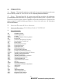
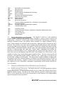
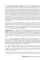
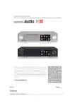
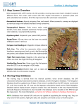
1
BELFORTINSTRUMENT 8009372353 www.DIGIWX.com DigiWx ® Automated Weather Observing System AWOS Operator Instruction Manual Proprietary Prepared in Response to FAA, Automated Weather Observing System (AWOS) Requirements July 2005 Table of Contents Operator Instruction Manual Paragraph Description 1.0 1.1 1.2 2.0 2.1 2.2 3.0 3.1 3.1.1 3.1.1.1 3.1.1.1.1 3.1.1.1.2 3.1.2 3.1.2.1 3.1.2.2 3.1.3 3.1.4 3.1.4.1 3.1.5 3.1.6.1 4.0 4.1 4.1.1 4.1.2 4.1.3 4.1.4 4.1.5 4.2 4.2.1 4.2.1.1 4.2.1.2 4.2.2 4.2.2.1 4.2.2.2 4.2.2.3 4.2.2.4 4.2.2.5 4.2.2.6 4.2.2.7 4.2.2.8 Page Introduction .................................................................................................. Purpose......................................................................................................... Scope............................................................................................................ Applicable Documents & List of Acronyms ................................................... Applicable Documents................................................................................... List of Acronyms........................................................................................... System Description and Overview ................................................................. Software and Peripheral Device Description and Capabilities......................... DigiWx Advisor™ Software ......................................................................... Data Speech Output Software ....................................................................... DigiWx Phone............................................................................................... DigiWx Voice ............................................................................................... Additional System Options ............................................................................ Central Data Store and Data Transmission..................................................... Website – Optional Service ........................................................................... DDR – Digital Data Receiver ........................................................................ RIF – Radio Interface.................................................................................... MCIF – Microphone Click Interface…………………………………………. DigiWx Advisor™ Display Screen................................................................. Charts ........................................................................................................... Operating Instructions................................................................................... Hand Held Display Unit................................................................................. Getting Started.............................................................................................. Detailed Description of Operator Controls and Functions .............................. Detailed Discussion of Button Operations ..................................................... Detailed Discussion of Display Data Overview .............................................. Data Status Indicators ................................................................................... Data Acquisition Terminal Unit and System Software.................................... Using the computer to operate the DigiWx System........................................ Using the mouse with DigiWx software......................................................... Using the DigiWx DATU computer keyboard ............................................... DigiWx Advisor Operator’s Screen ............................................................... Raw Data Chart ............................................................................................ Graphs .......................................................................................................... Configuration Settings................................................................................... Alerts ............................................................................................................ Entering and Disseminating NOTAMs........................................................... Augmenting and Overriding Automated Weather Reports ............................. History Database Maintenance ...................................................................... DigiWx Phone............................................................................................... 1 1 1 1 1 1 2 2 2 3 3 3 3 3 4 4 5 5 5 5 8 8 8 11 11 14 15 17 17 17 20 21 23 25 26 26 26 27 30 31 i BELFORT INSTRUMENT Proprietary Information 4.2.2.9 4.2.3 5.0 DigiWx Voice ............................................................................................... Procedures to Freeze Data for Accident or Incident investigations................. Customer Support and Assistance ................................................................. 31 33 33 Figures & Illustrations Figure 1 Figure 2 Figure 3 Figure 4a Figure 4b Figure 4c Figure 4d Figure 5a Figure 5b Figure 6 Figure 7 Figure 8 Figure 9 Figure 10 Figure 11 Figure 12 DigiWx Radio Interface (RIF) ....................................................................... 60 Minute Chart ............................................................................................ HHDU Display Functions.............................................................................. Typical HandHeld Computer Mouse ............................................................ Using a Computer Mouse.............................................................................. Standard Computer Keyboard Layout ........................................................... DigiWx Advisor Main Screen ....................................................................... History Chart Menu ...................................................................................... Raw History Chart Setup ............................................................................. Raw History Chart ........................................................................................ Wind Speed Graph ........................................................................................ DigiWx Advisor Menu Bar............................................................................ NOTAM Menu ............................................................................................. NOTAM Message Property Page .................................................................. DigiWx Phone Icon....................................................................................... DigiWx DTMF Display ................................................................................. 5 7 9 17 19 20 22 23 23 24 25 26 26 27 31 32 ii BELFORT INSTRUMENT Proprietary Information 1.0 INTRODUCTION 1.1 PURPOSE – This manual is written to comply with the system documentation requirements of FAA Advisory circular AC 150/522016C for an “Operating Instructions Manual.” 1.2 SCOPE – This manual provides the system owner and base operations and maintenance personnel with detailed instructions for operating the DigiWx weather system. It provides a basic overview of the system, system software capabilities and provides instructions for operation of the system computer terminal including procedures to extract data and enter and disseminate NOTAM information. 2.0 APPLICABLE DOCUMENTS & LIST OF ACRONYMS 2.1 APPLICABLE DOCUMENTS – FAA Advisory Circular AC 150/522016C 2.2 LIST OF ACRONYMS AC ALS AVG AWOS BIT CTAF DATU DC DCP DDR DMM DSL DTMF ELDF EPROM FAA FBO FCC FRDF FRU FSDO Hg HHDU ICAO ID INOP KT LED LRU MCIF MHz Alternating Current Ambient Light Sensor Average Automated Weather Observing System BuiltInTest Common Traffic Advisory Frequency Data Acquisition Terminal Unit Direct Current Data Collection Processor Digital Data Receiver Digital Multimeter Digital Subscriber Line DualTone MultiFrequency Endless Loop Dedicated Frequency Erasable Programmable ReadOnly Memory Federal Aviation Administration Facility Base Operator Federal Communication Commission Facility Reference Data File Field Replaceable Unit Flight Standards District Office Mercury Hand Held Display Unit International Civil Aviation Organization Identification Inoperative Knots Light Emitting Diode Lowest Replaceable Unit Microphone Click Interface Megahertz (million Hertz) 1 BELFORT INSTRUMENT Proprietary Information MOU MSL NAVAID NIST NOTAM OMM RAF REL HUM RIF RPM T1 UHF UNICOM VAC Memorandum of Understanding Mean Sea Level Navigational Aid National Institute of Standards and Technology Notice To Airman Operations and Maintenance Manual Regional Airway Facilities Relative Humidity Radio Interface Revolutions Per Minute Tcarrier 1 (digital transmission line, 1.544 Mbps, 24 voice channels) Ultra High Frequency Universal Integrated Communications (System) Volts Alternating Current VDC VDD VDU VHF VS Volts Direct Current Version Description Document (DigiWx® Configuration Baseline Document) Video Display Unit Very High Frequency Visibility Sensor 3.0 SYSTEM DESCRIPTION AND OVERVIEW – The DigiWx™ AWOS is a fully automated aviation weather observing and reporting system designed to support General Aviation and Charter pilots. A DigiWx™ AWOS system consists of wind speed, wind direction, temperature, humidity, barometric pressure and visibility sensors mounted on a rugged, aluminum tiltover tower. Sensor readings are monitored and processed by a digital processor located in the DCP enclosure. The processor uses sensor data to calculate the prevailing and gust wind components for preprogrammed runway headings. The DigiWx™ AWOS also calculates the altimeter setting, density altitude, condensation altitude, and dew point. All of this information plus the speed and direction of both prevailing and wind gusts, current surface temperature and visibility are broadcast on UHF 464 MHz by a FCC licensed transceiver located in the DCP enclosure. This data is then received and displayed at the FBO office Video Display Unit (VDU) where it is also available to remote users via the Internet and/or telephone dialin. The data is also received and displayed on the HandHeld Display (HHDU) which has a line of sight range of 10 NM and can be used either in flight or on the ground. The system reports weather conditions to pilots in the air primarily via the Pilot Activated Unicom or an Endless Loop Dedicated Frequency (ELDF) on a dedicated VHF frequency. DigiWx™ AWOS system software design incorporates plug and play simplicity for ease of installation, maintenance, upgradeability and an intuitive interface for ease of operation. 3.1 SOFTWARE AND PERIPHERAL DEVICE DESCRIPTION AND CAPABILITIES 3.1.1 DIGIWX ADVISOR™ SOFTWARE – The DigiWx Advisor™ is a Belfort proprietary software program that provides a PCbased graphical display of local weather data collected from the base DigiWx® Weather Station. The data can be viewed from the system PC terminal at the airport FBO or, if the optional Web Service has been purchased, on the Internet for preflight planning purposes and general airport operations. 2 BELFORT INSTRUMENT Proprietary Information The DigiWx Advisor™ has an event manager capability that provides visual alerts of important, possibly critical, weather conditions such as high density altitude or excessive crosswind component. The program captures all weather conditions to support aircraft accident or incident investigation if needed. All historical data is saved subject only to limitations of hard disk space. Current data is, optionally, also be transmitted to a central site where it is saved in a master database with online and offline backups for data safekeeping. Historical data saved at the master database is retained indefinitely. 3.1.1.1 DATA SPEECH OUTPUT SOFTWARE 3.1.1.1.1 DigiWx® Phone – The DigiWx® Phone augments the DigiWx Advisor™ program and will automatically answer a phone line and deliver current weather conditions as speech output. In order for the telephone answering and reporting system to function, a modem capable of voice output must be installed. If this option is purchased, the modem will be installed and configured at the Belfort factory. The DigiWx® Phone program will answer a call on the telephone line connected to the modem. The program will usually answer before the second ring at the modem. (The caller may hear three (3) or more rings depending upon the variables in the public telephone switching network.) Once DigiWx® Phone has answered the call, the program will query the database to retrieve the most current reading. The program will generate speech output into the modem for: Airport name, NOTAM message (if any), current winds and gusts, altimeter, visibility (if sensor is installed), temperature, dew point, relative humidity, density altitude and condensation altitude. The program will repeat the current conditions and will then terminate the call and hang up the phone line. Stale data threshold – A stale data threshold is preconfigured at the Belfort factory. If the most current data reading is older than the current clock time minus the stale data threshold interval, no weather parameters will be shown, and “Current data not available” will be output instead of the date and time. In the event that the stale data threshold has been exceeded, the speech message output will consist of the airport name and the phrase “Current data is not available.” 3.1.1.1.2 DigiWx® Voice – A separate program, called DigiWx® Voice, provides speech output through the CTAF/Unicom radio upon demand from a pilot’s radio. The installation, setup and operation of DigiWx® Voice are installed and configured at the Belfort factory. There is no operator setup or configuration required. Base Station – When DigiWx® Voice is installed, a base station transceiver approved or provided by Belfort must be used. The base station will function normally to conduct routine UNICOM communications in addition to pilotactivated weather broadcasts Radio Interface. The DigiWx® Voice optional feature is very reliable and once installed, should require no periodic maintenance or user support. If this feature is not functioning properly, contact Belfort customer support for assistance. 3.1.2 ADDITIONAL OPTIONAL FEATURES 3 BELFORT INSTRUMENT Proprietary Information 3.1.2.1 Central Data Store and Data Transmission – Available as a purchased system option, current data may also be transmitted to a central site where it is saved in a master database with online and offline backups for data safekeeping. A subsystem, running as a Windows Service, queries the local database every 10 seconds and transmits any new data to the central database. Queries into the database are made for new readings, for any changes to the airport configuration, and for any new NOTAMs entered. This subsystem connects to a .NET XML Web Service running at the central location and sends any new data discovered. The central location Web Service accepts the new data and records it into the central database. The Transmit subsystem waits for an acknowledgement from the Data Receiver and when the acknowledgement is received, a “synchronized” entry is made into a table in the database indicating that the record has been sent and received. In the event that the PC is without Internet connection for some time, the subsystem will automatically recover. When Internet connection is reestablished, the subsystem will transmit the most current reading and up to 40 older readings which had not yet been transmitted. This process will continue during each 10second interval until all the records have been transmitted. The data reception system is a .NET XML Web Service running at the central location. This system accepts new data from multiple DigiWx® sites and records the data into a central database. After the data is properly recorded in the central database, this service replies with an acknowledgement of data received. The acknowledgement consists of a list of the timestamps (from the local database) of records received and recorded. The data reception system does not alter in any way the data received from the local database. Database security The local DigiWx database is behind a firewall and the web services server has the Microsoft “Lockdown” tool applied. This means intrusion attempts are blocked and no response is sent to intruders. The web server where the DigiWx sites data are remotely archived also has the Microsoft “Lockdown” tool applied. There is no user activity on either the database server or web server. No downloads, no email, no web surfing. Retrievals of archived data from the remote database are by written request coordinated through Belfort Instrument Company only. 3.1.2.2 Website – optional service – The DigiWx® website for each installation runs on a central web server. Each website is dynamic and uses the most recent data transmitted and received into the central database. The html page for the DigiWx® website is similar to the DATU Operator’s Screen, albeit with links to National Weather Service radar websites and other local informational websites. The html page will automatically refresh every 60 seconds, and the user may cause an immediate refresh by clicking on a refresh button. 3.1.3 DDR – The DDR (Digital Data Receiver) Interface is a “blackbox” component with power switch, AC adapter jack, antenna, and RS232 (serial port) jack. The DDR Interface box contains a receiver for the transmissions from the weather tower, and signal processing components to convert the received data into a serial data stream for input to the base station computer’s Serial port interface. As each data record is received at the computer from the DDR Interface box, a software component reads the data from the Serial port and puts a time stamp into the record. This record 4 BELFORT INSTRUMENT Proprietary Information is then written into the local database. Only the sensor parameter data received from the DDR Interface box is written to the database. The constant components such as Latitude and Longitude are discarded. The data capture component runs as a Windows Service and automatically starts when Windows starts. This background operation does not require, nor permit, any input from the Operator. 3.1.4 RIF RADIO INTERFACE – In addition to the Base Station transceiver, DigiWx® Voice incorporates a Radio Interface Device (RIF). This device serves as the interface between the Belfort provided Personal Computer and the UNICOM base station. Figure 1 – DigiWx® Radio Interface (RIF) The RIF Serves as a conduit for the speech synthesis of the current weather conditions transmission. 3.1.5 MCIF – MICROPHONE CLICK INTERFACE – DigiWx® Voice incorporates a Microphone Click Interface Device (MCIF). This device serves as the interface between the Belfort provided Personal Computer, the RIF, and the UNICOM base station. 3.1.6. DIGIWX ADVISOR™ DISPLAY SCREEN – On the computer display configuration screen, the operator can toggle the display of METAR data on or off. The operator can select the display of certain data in English units or Metric units. If the selection is changed on either or both METAR or Metric, the Operator’s Screen program must be stopped and restarted before the change will take effect. The program can be stopped by clicking the X in the upper right hand corner of the display window or by selecting “exit” from the “File” dropdown menu. Restart the program by double clicking the DigiWx® FBO icon on the windows desktop. 3.1.6.1 Charts 60minute and 48hour Charts Charts showing recent historical readings (60 minutes and 48 hours) are available from within the Operator’s Screen. A dropdown box allows selection of either the 60Minute chart or the 48 Hour chart. The timestamp and sensor readings comprise the columns of each chart. The charts 5 BELFORT INSTRUMENT Proprietary Information show the first reading received from the sensor package in each time interval, beginning at the top of the chart with the most recent time and continuing to the bottom with older readings. The charts show only the first reading in the interval. No averaging of data is done. A blank line will be displayed if no data record has been received within the time interval. The time interval for the 60Minute chart is one (1) minute. The time interval for the 48Hour chart is fifteen (15) minutes. 6 BELFORT INSTRUMENT Proprietary Information Figure 2 – 60 Minute Chart 7 BELFORT INSTRUMENT Proprietary Information 4.0 OPERATING INSTRUCTIONS 4.1 HAND HELD DISPLAY UNIT – One (HHDU) is provided with each DigiWx® system for use in monitoring system outputs. The following information provides the DigiWx® operator and maintenance personnel with instructions on how to use the HHDU to monitor and verify actual DigiWx® system outputs. 4.1.1 GETTING STARTED Open the Box and Check the Contents The following items are included: · · · · · · One DigiWx® – Hand Held Receiver – 3" X 6" X 1.25" w/digital display. One Antenna Four AAA batteries Power Supply (optional) Carrying Case (optional) User Manual (the one you're presently reading) a. Remove the protective plastic cover. b. Open the battery cover on the back of the unit by pressing down and sliding the battery cover downward. c. Place the four AAA batteries in the battery sockets as indicated. Ensure proper polarity is observed while inserting batteries. Slide the battery cover back over the batteries until it clicks into place. d. If you have purchased the optional AC Power Supply, plug it into a 110 VAC wall outlet and insert the 12vdc plug into the hand held display unit. Screw the antenna into the antenna receptacle at the top of the display. Press the ON/OFF button to turn on the device. CAUTION: The AC Power Supply will not function as a battery charger. It is only used for supplying power to the unit from 110 VAC wall outlets. Also: Do not use rechargeable batteries in this unit. 8 BELFORT INSTRUMENT Proprietary Information Figure 3 – HHDU Controls and Display Functions Antenna: The black fourinch antenna should be tightly screwed into the coaxial connector at the top of the unit. ON/OFF button (1) Press to turn the unit on. If there isn’t a DigiWx® weather tower (transmitter) within range only the runway graphic will show without data. Wait until the “OK” is displayed next to the DATA (9) location on the display before proceeding. It may take several seconds for the data to be verified as reliable for use. REFRESH button (5) – Press this button to update the display and “capture and hold” current weather data. 9 BELFORT INSTRUMENT Proprietary Information NOTE: The REFRESH button (5) must be depressed every five (5) minutes to update the weather data, or the word “OLD” will appear to the right of the runway graphic next to the DATA position (9). You should see all of the weather data appear on the screen along with the latitude (17) and longitude (17) of the DigiWx® weather tower that is transmitting the Data. WHEN activated you will see the airport’s designator (11). Look at the Average Wind (12) and Gust Wind (13) indications and select the desired runway heading (8) by pushing the RUNWAY heading buttons (6). NOTE: If there are runway headings programmed into the DigiWx® tower for the airfield location the Tower will only display those headings, not all 36 possible headings. Many heliports and seaplane bases will want to display all 36 possible headings (360 degrees in 10degree increments, i.e. runway 33 is runwayheading 330). Push the GUST button (4) and note that the arrows on the runway graphic indicating headwind and crosswind components of gusts may change. The word “GUST” will be displayed down the center of the runway graphic. Pushing the “GUST” button (4) again will return the wind component displayed on the runway graphic to average wind components. NOTE: If the headwind arrow is not there, look below the runway graphic, a tailwind arrow may be displayed with tailwind speed in knots. If an “ALERT” message is displayed down the center of the runway it means that the DigiWx® tower is sending one of nine possible alert messages. By pressing the PAGE button (3), you may scroll to a second page of information for the alert message. Pressing the PAGE button (3) again will return you to the weather data page. If no alert message exists, scrolling to the second page with the PAGE button (3) will display “no alert” on the second page. The LIGHT button (2) activates the backlight for the display. This allows you to see the display in a darkened room (cockpit at night). If you activate this feature during the day, it will not aid in viewing the display and will only decrease the battery life. Pressing the LIGHT button (2) again will turn off the backlight and save battery power. By pressing and holding down the RUNWAY + (plus) button (6) for more than 1.5 seconds the DigiWx® display will LOCK onto the displayed runway. The DigiWx® will not change to a signal from another DigiWx® tower until the RUNWAY - (minus) button (7) is pushed and held for more than 1.5 seconds. 10 BELFORT INSTRUMENT Proprietary Information 4.1.2 DETAILED DESCRIPTION OF OPERATING CONTROLS AND DISPLAY FUNCTIONS – When you use the DigiWx® hand held digital weather display you will find that it will only operate within range of a DigiWx® weather tower. The DigiWx® signal will adequately penetrate a hangar or an office building’s walls with its FM modulated digital signals. It does, however operate best as a “line of sight” transmission device. It will consistently operate within 10 miles “line of sight” and may operate under ideal conditions up to 20 miles. Due to this extended range, there may be possible interference if two or more DigiWx® systems are within this operating range. To correct for this the DigiWx® will listen on two different frequencies in the 460 MHz range. The device will call both f1 and f2 simultaneously and will discriminate between the two signals thereby reducing spurious obstruction. The following is a description of this process. The DigiWx® transmits every 5 seconds on either frequency f1 or f2. When the unit is initially powered up the receiver listens to f1 for 8 seconds. If it receives no signal, it switches to f2 and listens for 8 seconds. If it receives no signal on f2, you are out of range. It will then switch back to f1. If you are currently receiving a message and lose your signal, the receiver will wait 13 seconds and then switch to the other frequency. If you do not have a “good signal” and hence accurate data transmission from the weather tower, the display will not show “OK” after the Data position (9) on the display. Once you are receiving a station you want to stay with, you may use the “data lock” feature to “lock” onto that station. There are five main things to remember from the above information: · You can receive information from more than one DigiWx® weather tower. · You are able to select and lock on to a desired weather tower. · You should always check to verify that the data displayed is from the weather tower you want information from. · The system is designed to only display the Data “OK” sign if the data is of an adequate quality. · Always be alert to the Latitude (17) and Longitude (17) displayed and the airport designator (11). 4.1.3 DETAILED DISCUSSION OF BUTTON OPERATION ON/OFF (1) Turn on the DigiWx® hand held display unit by briefly holding down the ON/OFF button (1). The display will then show a runway graphic. When a valid transmission is received, the data “OK” indicator will illuminate and the rest of the weather data will be displayed. Checking validity of the data may take several seconds. The LIGHT button is the only button that works until the unit is turned on. Turn off the unit using the same ON/OFF button. 11 BELFORT INSTRUMENT Proprietary Information NOTE: If no buttons are pushed for a period of 10 minutes the Auto shut down will activate and the unit will automatically turnoff to conserve power. LIGHT (2) The LIGHT button (2) controls the display backlight function. When the unit initially is turned on the backlight function is off. The operator must press the LIGHT button (2) to activate the backlight. If the unit is not used for a period of 10 seconds, the backlight will go off. Pressing any button will reactivate the backlight. If the unit is not used for 5 minutes, the automatic reactivation feature will turn off. PAGE (3) The PAGE button (3) controls the displayed information. There are 2 pages of displayed information. Page 1 contains the weather data and runway graphic data. Page 2 contains ALERT messages transmitted from the tower. When an ALERT message is transmitted, the word “ALERT” will be displayed on the runway graphic. Push the PAGE button (3) to toggle to page 2 where the ALERT message is displayed. Only the ON/OFF, LIGHT and PAGE buttons are activated while page 2 is displayed. GUST (4) The GUST button controls the wind information displayed on the Runway Graphic. You may either select the average wind components or gust wind components. The runway graphic will display arrows pointing to the left, right, top or bottom that will tell you the runway wind components. This way you will know at a glance whether the wind is a left or right crosswind, a headwind, or a tailwind for the runway you have selected. If the arrow is at the top of the runway graphic, it is a headwind. If the arrow is at the bottom, it is a tailwind for that runway heading. When you turn the unit on it will display the average wind components on the runway graphic. When you push the GUST button (4) the word “GUST” will appear on the runway graphic and the components of the gust wind conditions will be displayed. The average wind means, the average over a twominute period and the Gust wind means, the peak value of wind over a twominute period. REFRESH (5) Each time the REFRESH button (5) is pushed the unit captures the current weather data and holds it in the display until you push the button again. This allows you capture the weather data when you want to keep it available for quick reference. However, this may also allow the data become too old to represent current weather conditions. After five minutes, the Data is considered too old and the data “OLD” indicator comes on to the right of the runway graphic. This reminds you to press the REFRESH button (5) for current weather data and the “OLD” indicator turns off. 12 BELFORT INSTRUMENT Proprietary Information NOTE: If new data is not available, the display will not REFRESH and will display the “OLD” data. · If the “lockin” function is activated the REFRESH button (5) will only refresh data from a “locked” in DigiWx® weather tower site. To refresh data from another site, the “lock in” function must be deactivated. · RUNWAY (+) (6) The RUNWAY (+) button (6) has several uses and only functions when the display has captured weather data. RUNWAY (+) (6) will toggle through each runway heading available from the DigiWx® weather tower. For Towers with a limited number of runways, it will only permit selection of those runways at that site. For other locations, pressing the RUNWAY (+) button (6) will increment the runway heading displayed at the bottom of the runway graphic by 10degree increments. Each time a runway heading is changed the new wind components are calculated and displayed instantly next to the runway graphic. RUNWAY (+) (6) will lock onto a particular DigiWx® weather tower. By pressing and holding this button for more than 1.5 seconds the lock symbol will appear on the left side of the runway graphic. This will lock the data on to the DigiWx® site currently displayed. If you are not receiving data from the DigiWx® site you desire but believe you are within range, you must first toggle to the desired site information by pushing the REFRESH button (5) until the desired data is displayed. You then capture the desired data by pressing and holding the RUNWAY button for more than 1.5 seconds. RUNWAY () (7) The RUNWAY () button has three functions and only operates when weather data is displayed. It will decrement the runway heading on the runway graphic. · It will unlock the display from a lockedin DigiWx® site. · It can be used to force the unit to listen to a different DigiWx® site, when another is available. · Pressing and releasing the RUNWAY () button (7) within 1.5 seconds will decrement the runway heading number and automatically update the wind component data to the new heading. This function is identical to the RUNWAY (+) increment described above except that it scrolls down to a lesser runway heading unless it is already at the lowest. In that instance, it will roll over to the next available heading. If the RUNWAY () button (7) is held for a minimum of 1.5 seconds while the receiver is locked on to a particular DigiWx® site, the “lock” symbol to the left of the runway graphic will disappear. If you then press the REFRESH button (5), the unit will receive weather data from the nearest available DigiWx® site. 13 BELFORT INSTRUMENT Proprietary Information If the RUNWAY () button (7) is held for a minimum of 1.5 seconds when the unit is NOT locked to a particular DigiWx® site, the unit will listen to transmissions from alternate sites. Press the REFRESH button to display this site data. This is a way to “force” the DigiWx® to listen to alternate sites. 4.1.4 DETAILED DISCUSSION OF DISPLAYED DATA OVERVIEW: The DigiWx® hand held weather receiver display is divided into two parts. · The upper half of the display contains the runway graphic with associated runway heading and wind components. It also contains the DATA “OK”, “OLD”, and “LOCK” indications and airport identifier. · The lower half of the display contains the numerical weather data, the latitude and longitude of the DigiWx® site received by the display and the lowbattery alert warning; “BAT LO”. If any of the DigiWx® sensors (wind speed, direction, temperature, humidity or pressure) is deemed by the DigiWx® site operator or the site transmitter to be inoperative (broken), the tower can be told to transmit an “ALERT” message. The message will be displayed down the middle of the runway graphic as an “ALERT”). The second page will indicate the inoperative sensor. Any data on the display that relies on the inoperative sensor will not be displayed. Instead, a “” will be displayed at that location. NOTE: Numerical data is rounded to the nearest increment. For example, a temperature of 12.4°C will be rounded down to 12°C while 12.5°C will be rounded up to 13°C. Altimeter Settings are rounded to the nearest 0.01 of an inch. Rounding occurs only as the last step in the calculation to maintain precision in making each calculation. WIND COMPONENTS AND RUNWAY GRAPHIC (8) The RUNWAY GRAPHIC display (8) shows a diagram of a runway from the approach end. It shows the runway boundary, centerline and runway heading at the bottom of the runway graphic, as you would see it on final approach. The HEADWIND and CROSSWIND components of wind are shown on the graphic with arrows showing direction relative to the selected runway and the wind component speed in knots. NOTES: · The TAILWIND component of wind will not be displayed unless there is a tailwind component to the wind. · The maximum displayed wind component is 99 knots even if it exceeds this velocity. The component velocities of wind can be based on AVERAGE wind speed and direction or on GUST wind speed and direction. If you have selected the GUST components of wind to be 14 BELFORT INSTRUMENT Proprietary Information displayed by pressing the GUST button (4), the word “GUST” will appear on the runway centerline graphic. As wind shifts with gusts, the crosswind component of wind may shift from one side of the runway to the other in severe gust conditions. This information is “real”. The average wind is giving the components of wind direction averaged over 2 minutes. The GUST wind components of wind direction are taken at the instant the highest wind speed is recorded over the same 2minute period. As significant wind shifts often occur during gusts, a shift in crosswind components from one side of the runway may occur. Alerts from the DigiWx® site are indicated via the RUNWAY graphic (8). When an Alert message is programmed into the DigiWx® ground site the word “ALERT” will flash across the runway graphic. When you press the PAGE button (3), the Alert message will be displayed. When you push the PAGE button (3) to return to the weather data page the “ALERT”' message will still be displayed but it will not be flashing. Whenever a new alert is transmitted from the DigiWx® site, the “ALERT” message will flash. As soon as an ALERT message is transmitted from a DigiWx® site, it will be displayed. 4.1.5 DATA STATUS INDICATORS (7 & 8) – Two data status indicators are shown on the DigiWx® display. The first is the DATA “OK” indicator (9) to the left of the runway graphic and the second is the DATA “OLD” indicator (9) to the right of the airport indicator. The DATA “OK” indicator (9) to the left of the runway graphic indicates “OK” if valid data is being received. If 30 seconds elapse without receiving valid data, the “OK” indicator will disappear. The DATA “OLD” indicator (9) to the right of the runway graphic is only displayed if the data displayrd on the unit is over five minutes old. It is a reminder to press the REFRESH button (5) to update the displayed information. When you depress the REFRESH button (5) to display fresh weather information the “OLD” display disappears. NOTE: If the device receives no new data when the refresh button is pushed, the DATA “OLD” indicator (9) stays on. THE LOCK SYMBOL The lock symbol (graphic of a lock) will be shown to the left of the runway graphic between the DATA and AVG. WIND indicators. When the unit is “locked” on to a specific DigiWx® weather site, this symbol will be visible. When the symbol is not there the, DigiWx® unit is scanning for the nearest available DigiWx® signal. AIRPORT DESIGNATOR (11) Each DigiWx® weather site may be programmed with a specific airport identifier, of up to five characters in length. If the displayed weather site has a designator, it will be displayed to the right of the runway graphic between the DATA and Temperature indicators. 15 BELFORT INSTRUMENT Proprietary Information AVERAGE WIND (12) The average wind speed, averaged over a twominute interval, is displayed after the AVG. WIND position on the unit. It is calculated as the average wind speed and direction over a twominute period and displayed as Wind Direction in magnetic degrees and velocity in knots. Maximum velocity reported by the transmitter is 99 knots. GUST WIND (13) The gust wind speed is calculated as the peak wind speed, and the wind direction, as measured over a twominute period. It is displayed in degrees of magnetic heading and as velocity (in knots). Every two minutes the DigiWx® site computer captures the highest wind speed sampled over a twominute period and transmits it to the hand held display. If the highest gust recorded is at the beginning of a twominute sampling period and the subsequent twominute period records no higher wind velocity, it is possible to display a gust condition that is 4 minutes old. Therefore, you may be observing the highest gust velocity that is up to 4 minutes old. Maximum Gust velocity displayed is 99 knots. ALTIMETER SETTING (14) The Altimeter Setting displayed (14) indicates the DigiWx® site barometric pressure reading adjusted for elevation above sea level and displayed in inches of mercury (Hg). DENSITY ALTITUDE (15) The Density Altitude display (15) is based on current temperature and barometric pressure at the DigiWx® transmitting site. It does not include humidity factors in the calculation, which could alter the precision of the calculation. Its range is limited to 13,382 feet MSL as the algorithms used in the calculation are not as accurate as required over this elevation. CONDENSATION ALTITUDE (16) (MSL Feet) The Condensation Altitude display (16) is the altitude in which condensation (clouds) will occur given normal adiabatic conditions. It assumes a normal adiabatic laps rate of 2 degrees per one thousand feet of elevation and calculates the condensation altitude based on the spread between the ground temperature and the dew point temperature. It also takes into account runway altitude and displays the condensation altitude in feet MSL up to 13,382 feet MSL. LATITUDE and LONGITUDE (17) The Latitude and Longitude displayed (17) is the information programmed into the DigiWx® site transmitter for the information displayed on the unit. It is used as the basis for locking onto a specific site when the LOCK feature is activated. TEMPERATURE (18) The Temperature displayed (18) is the current temperature at the selected DigiWx® site in degrees Celsius. The range is 40 to +85 degrees Celsius. DEW POINT (19) 16 BELFORT INSTRUMENT Proprietary Information The Dew Point displayed (19), is the calculated dew point. This is based on the current temperature and humidity at the DigiWx® site displayed. When Dew Point and Temperature are close to each other, clouds or fog are likely at the displayed site. RELATIVE HUMIDITY (20) The Relative Humidity displayed (20) is the current reading transmitted from the DigiWx® site displayed. Its range is 0 to 100 percent and is an indication of the moisture content of the air at the selected DigiWx® site. BATTERY LOW INDICATOR (21) The Battery Low indicator (“BAT LO”) is not shown on Figure 1.1 but will appear below the REL HUM displayed data if battery voltage drops to the level indicating the need for battery replacement. The amount of time left in the batteries when this indicator is on is a function of the type of battery used. It is recommended that batteries be changed when this indicator is displayed. If battery power drops below this level, the display will automatically shut down. 4.2 DATA ACQUISITION TERMINAL UNIT AND SYSTEM SOFTWARE OPERATION – The DATU is a commercial off the shelf computer configured specifically for the DigiWx® system at the Belfort factory. This computer must be dedicated to the DigiWx® system and no other software is authorized to be loaded or run on this computer. The following DigiWx Advisor™ software operating instructions and information are provided to enable the DigiWx® base operator to effectively use the DigiWx® system. 4.2.1 USING THE COMPUTER TO OPERATE THE DIGIWX SYSTEM A minimum of operator computer skills are required to operate the DigiWx Display Acquisition Terminal and software programs. However the following basic general computer operator skills are needed to operate DigiWx system software. 4.2.1.1 USING THE MOUSE WITH THE DIGIWX SOFTWARE Right Mouse Button Left Mouse Button Figure 4a Typical handheld computer mouse A mouse is a hand held computer input device that enables the computer operator to interact with software programs. Moving the mouse on the mouse pad controls the movement of a pointer on the computer display screen. As you slide the mouse on the mouse pad you can point to and select various objects and icons on the computer screen. Clicking on the icons or objects will 17 BELFORT INSTRUMENT Proprietary Information control or initiate various actions within the computer software program. The pointer is normally displayed as an arrow but it can change shape. When the pointer on the computer screen changes from an arrow to a pointing hand symbol while hovering over an object, it indicates that clicking on this object will link to or open another display screen or file. When viewing text or numerical data the mouse pointer will change to a blinking vertical line indicating the specific location in the text where the pointer/cursor is located. There are four common mouse click actions that all users should be familiar with: SingleClick – Click (press) the left mouse button once while pointing to an object on the computer screen. This action is used to select but may or may not initiate a specific action in the software program. DoubleClick – Quickly press and release the left mouse button twice. A double click is sometimes needed to initiate a specific action in the software program. RightClick – Press and release the right mouse button once. This action will cause a shortcut dropdown menu to appear on the display screen. Click and Drag – Press down and hold the left mouse button down while sliding the mouse across the mouse pad. This action will enable the operator to select text or specific data to be copied or move an object or file on the computer screen. This action can also be used to move or copy files within Windows applications. This later use of the Click and Drag action will rarely be needed while operating DigiWx software application programs. The following illustrations show typical actions and uses of a mouse with the DigiWx Advisor display program. 18 BELFORT INSTRUMENT Proprietary Information Clicking this X will close the DigiWx Advisor display program Click on this slide arrow to scroll up the page within the visible window Figure 4b Using a Computer Mouse Clicking either of these arrows will open a dropdown menu to select the type of graph or chart to be displayed 19 Click this slide arrow to scroll down the page within the visible the window BELFORT INSTRUMENT Proprietary Information Select the type of graph to view in this dropdown menu box Figure 4b (Continued) Using a Computer Mouse 4.2.1.2 USING THE DIGIWX DATU COMPUTER KEYBOARD Figure 4c Standard Computer Keyboard Layout The DigiWx DATU uses a standard 101 key computer keyboard. The standard computer keyboard has three main sections. The section of the keyboard in the bold outline above is similar to a typewriter keyboard with some special additional function key pads on the top row. These function keys are not used when operating the DigiWx system. The additional Ctrl and Alt keys 20 BELFORT INSTRUMENT Proprietary Information on either side of the space bar are also not used for operation of the DigiWx system. The section of the keyboard to the immediate right of the standard typewriter keypad section contains navigation arrow keys for display screen navigation up, down, left and right. In general these keys are not needed for operation of the DigiWx system since most navigation on the computer display screen is more conveniently accomplished using the computer mouse. When the Num Lock key is pressed and the Num lock light is displayed the third section of the keyboard on the far right of the keyboard is a numerical keypad that can be used to enter numerical data. Numerical data can either be entered from the typewriter section of the keyboard or the keypad section whichever is more convenient for the operator. Normally, the Num Lock feature is automatically set when the computer starts up. If the Num Lock key is again pressed the Num Lock light will go out and this section of the keyboard can then also be used to navigate on the computer display screen. There is no need to use this section for display navigation since most navigation on the computer display screen is more conveniently accomplished using the computer mouse. 4.2.2 DIGIWX ADVISOR™ OPERATOR’S SCREEN – The Operator’s Screen may be started by the operator at any time by double clicking the DigiWx® FBO icon on the Windows desktop. It is not necessary that the Operator’s Screen be running in order for the system to function. Data received from the DDR Interface will be recorded in the database regardless of whether the Operator’s Screen is running or not. The Operator’s Screen provides text and graphical output of current data readings. The header at the top of the operator’s screen shows the airport name, identifier (ICAO), town and state. To the immediate right of the airport identification area is an area with field altitude, latitude, longitude, and CTAF/Unicom frequency. A panel running along the left side of the screen presents textual display of the date and time (Zulu), and the weather parameters of the most current reading. Some text fields are not always visible. For example, a text line may show Wind Chill, Heat Index or nothing depending on current conditions. A horizontal band at the bottom of the screen contains an area that will normally be blank. This area is used to show flashing red text when an (operator settable) alert has occurred. Setting the alert conditions is described in its own section below. A horizontal band at the bottom of the screen is used to show the current readings in a METAR format. The METAR display may be toggled on or off on the Display Configuration page which is described in the Configuration section of this document. The METAR display, if toggled on, will show immediately above the area where alerts are displayed. 21 BELFORT INSTRUMENT Proprietary Information Figure 4d – DigiWx Advisor™ Main Screen 22 BELFORT INSTRUMENT Proprietary Information 4.2.2.1 RAW DATA CHART – Several types of history data charts are available for showing the raw data from the database. Charts may be displayed by selecting the “History” menu item from the top line menu bar and selecting one of the options for charting history data. Figure 5a –History Chart Menu When the “Chart Data by time period” dialog box appears, enter the time period to be displayed in the Chart Setup screen as shown in Figure 5b. Figure 5b – Raw History Chart Setup When the From and To date and time have been entered, the Chart Data pushbutton will become active. Clicking on the “Chart Data” pushbutton will extract all readings from the database for the time period selected and will display these in a chart as shown in Figure 6. 23 BELFORT INSTRUMENT Proprietary Information Figure 6 – Raw History Chart 24 BELFORT INSTRUMENT Proprietary Information 4.2.2.2 Graphs – Graphs of each of the weather parameters, showing the most recent 50 changes, are available from within the Operator’s Screen. A dropdown box allows selection of any one of the sensor readings. Only one sensor reading may be shown on each graph. Each graph is dynamically prepared and scaled to allow the maximum and minimum values reported to be show. The Y axis of the graph shows the range of values displayed on the graph. The Xaxis of the graph is the time scale. The time scale will be dynamically adjusted to cover the range of the readings displayed. If there have been less than 50 changes for a particular sensor within the most recent 24 hour period, the graph will show only those changes for the last 24 hours. Figure 7 – Wind Speed Graph 25 BELFORT INSTRUMENT Proprietary Information 4.2.2.3 CONFIGURATION SETTINGS – Except for entering NOTAMs, all systems configuration settings are preconfigured and password protected at the Belfort factory. No changes to software configuration settings are authorized without specific direction and consultation from the Belfort factory. Figure 8 – Menu Bar 4.2.2.4 ALERTS – The system monitors the current data and if the alert setting criteria is met or exceeded, flashing red text will appear on the Operator’s Screen to indicate the condition. The flashing Alert text on the Operator’s screen will be continuously displayed as long as the alert condition exists. When the alert condition no longer exists, the flashing text will automatically disappear. 4.2.2.5 ENTERING NOTAMS (NOTICES TO AIRMEN) – NOTAMS may be entered on the property page located at the NOTAMs Menu Item. Figure 9 – NOTAM Menu Any number of NOTAMs may be entered. Each NOTAM will have an expiration date and time. Any number of NOTAMs may be “active” (i.e. unexpired), but only the most recently entered unexpired NOTAM will be displayed. Once a NOTAM has been entered, it cannot be modified or deleted. This ensures the integrity of the data. NOTAMs will appear immediately after they are 26 BELFORT INSTRUMENT Proprietary Information entered and someone may see and act upon the NOTAM information. If a NOTAM is entered erroneously, the proper way to recover is to immediately enter another NOTAM with the correct information and set an expiration date/time that is the same as the incorrect NOTAM. In this way, both the correct and the incorrect NOTAM will expire at the same time, and the incorrect NOTAM will never be displayed. Figure 10 – NOTAM Message Property Page 4.2.2.6 AUGMENTING AND OVERRIDING AUTOMATED WEATHER DATA – The DigiWx system is fully automated and a very reliable system that uses built in error checking algorithms to alert users and system operators of out of tolerance performance. It is unlikely that the system will report inaccurate weather data. However, should one or more DigiWx sensor(s) become inoperative or start reporting erroneous data, use the following procedures to temporarily manually report and augment DigiWx automated weather reports: 1. Collect Weather Observation data from a nonDigiWx source 2. Perform the following steps to turn off existing DigiWx observations a. DigiWx Advisor and DigiWx Phone 1) Click on the Configuration menu selection in DigiWx Advisor 2) Select Display from the menu selections 3) Enter Username 4) Enter Password 5) Click OK 27 BELFORT INSTRUMENT Proprietary Information 6) Locate the weather observation parameter from the list in the “Suppress Display of Data Parameters” section. 7) Click the check box in front of the weather observation parameter being overridden causing a check to appear in the check box. 8) Click Apply 9) Click OK 10) Shut down DigiWx Advisor by clicking on the File menu selection 11) Select Exit from the menu selection 12) Restart DigiWx Advisor by double clicking on the DigiWxFBO icon on the desktop. 13) Confirm that the weather observation has been replaced with dashes. b. DigiWx Voice 1) Click on the Setup menu selection in DigiWx Voice 2) Select Message from the menu selections 3) Enter Password 4) Click OK 5) In the Message Dialog click the check box in front of the weather observation parameter setting the state to “unchecked”. 6) Click OK 3. Add the manually collected observation to the NOTAM. a. DigiWx Advisor and DigiWx Phone 1) Click on the NOTAM menu selection in DigiWx Advisor 2) Select NOTAM Message from the menu selections 3) Enter the manually collected observation in the text box labeled New Message Note for DigiWx Phone: Enter the observation parameter name then the observation so that both will be announced in the DigiWx Phone message. Example: Wind Speed 21 knots. 4) Set when the NOTAM is to expire. 5) Click Apply 6) Click OK b. DigiWx Voice 1) Click on the Setup menu selection in DigiWx Voice 2) Select NOTAM from the menu selections 3) Enter Password 4) In the NOTAM dialog in the “Enter NOTAM to be spoken” enter the observation parameter name then the observation so that both will be announced in the DigiWx Voice message. Example: Wind Speed 21 knots. 5) Select Airport, NOTAM, and weather to include the NOTAM in the normal DigiWx Voice message. 6) Click OK 4. Check that the manual override has been successful a. DigiWx Advisor Confirm that the NOTAM is being displayed on the orange bar starting in the upper right corner of the window and is correct. b. DigiWx Phone Call the phone number assigned to the DigiWx system and listen to the message to confirm that the NOTAM was included and is correct. 28 BELFORT INSTRUMENT Proprietary Information c. DigiWx Voice Using another radio tuned to the correct UNICOM frequency, say the DigiWx Voice phrase that triggers the DigiWx Voice system to broadcast its message. Listen to the message to confirm that the NOTAM was included and is correct. 5. Reset system back to automatic observations a. DigiWx Advisor and DigiWx Phone 1) Click on the Configuration menu selection in DigiWx Advisor 2) Select Display from the menu selections 3) Enter Username 4) Enter Password 5) Click OK 6) Locate the weather observation parameter from the list in the “Suppress Display of Data Parameters” section. 7) Click the check box in front of the weather observation parameter being cleared causing the check to be removed from the check box. 8) Click Apply 9) Click OK 10) Shut down DigiWx Advisor by clicking on the File menu selection 11) Select Exit from the menu selection 12) Restart DigiWx Advisor by double clicking on the DigiWxFBO icon on the desktop. 13) Confirm that the weather observation is once again being updated automatically by watching for changes. b. DigiWx Voice 1) Click on the Setup menu selection in DigiWx Voice 2) Select Message from the menu selections 3) Enter Password 4) Click OK 5) In the Message Dialog click the check box in front of the weather observation parameter setting the state to “checked”. 6) Click OK 6. Cancel the NOTAM a. DigiWx Advisor and DigiWx Phone 1) Click on the NOTAM menu selection in DigiWx Advisor 2) Select NOTAM Message from the menu selections 3) Enter Username 4) Enter Password 5) Click OK 6) Enter a new NOTAM message in the text box labeled New Message. 7) Set when the NOTAM is to expire. Note for DigiWx Advisor: The only way to remove a NOTAM that has not expired is to insert a new NOTAM. Create a NOTAM using the process outlined above and give it the same expiration date and time as the previous NOTAM you are canceling. 8) Click Apply 9) Click OK 29 BELFORT INSTRUMENT Proprietary Information b. DigiWx Voice 1) Click on the Setup menu selection in DigiWx Voice 2) Select NOTAM from the menu selections 3) Enter Password 4) Select None 5) Click OK 7. Check that clearing the manual override has been successful a. DigiWx Advisor Confirm that no NOTAM is being displayed on the orange bar starting in the upper right corner of the window. b. DigiWx Phone Call the phone number assigned to the DigiWx system and listen to the message to confirm that no NOTAM was included. c. DigiWx Voice Using another radio tuned to the correct UNICOM frequency, click the microphone the set number of timesthat triggers the DigiWx Voice system to broadcast its message. Listen to the message to confirm that no NOTAM was included. 4.2.2.7 HISTORY DATABASE PERIODIC MAINTENANCE – It may be necessary, depending upon hard disk free space availability, to delete older entries from the local database after a period of operation. Computer hard drives shipped with current systems have ample storage space to preclude the need to archive any data for at least 10 years from date of installation. A separate program will be made available if it becomes necessary (or desirable) to archive these older entries. 30 BELFORT INSTRUMENT Proprietary Information 4.2.2.8 DIGIWX PHONE – The DigiWx® Phone program is an optional component of the DigiWx® system. If DigiWx® Phone is installed and is running, an icon representing a telephone or stop sign will appear in the Windows System Tray (lower righthand corner of the desktop). When the program is ready to answer phone calls, the icon will change to a telephone. The phone icon will be black when the program is waiting for a Figure 11 DigiWx® Phone Icon call, and will change to red when the program is servicing a phone call. DigiWx® Phone depends upon the PC having a voicecapable modem installed and properly configured. The installation and configuration of the modem will be preconfigured at the Belfort factory and is beyond the scope of this document. If the phone Icon is not present in the system tray or has changed to a stop sign, the phone program has stopped and must be restarted manually in order to resume answering the phone. Right click on the Icon and select “answer calls.” If the Icon does not change back to a telephone, contact Belfort customer support for assistance in resolving the problem. 4.2.2.9 DIGIWX® VOICE – A separate program, called DigiWx® Voice, provides speech output through the CTAF/Unicom radio upon demand from a pilot’s radio. The installation, setup and operation of DigiWx® Voice are installed and configured at the Belfort factory. There is no operator setup or configuration required. This optional feature is very reliable and once installed, should require no periodic maintenance or user support. If this feature is not functioning properly, contact Belfort customer support for assistance. COMPONENTS: Base Station – A base station approved or provided by Belfort must be used. The base station will function normally to conduct routine UNICOM communications in addition to voice activated weather broadcasts. RIF The Radio Interface (RIF) device serves as the interface between the Belfort provided Computer and the UNICOM base station. The following Additional functionality features are included with the Radio Interface device: MCIF – The Microphone Click Interface (MCIF) device serves as the interface between the Belfort provided Computer, the Unicom base station, and the RIF.. Microphone Input – When used, the base station microphone input will be passed through the radio interface unit. This enables the base station operator to override DigiWx® Voice weather transmissions by keying the microphone push to talk switch and speaking through the microphone in normal FBO or base station operations. Three Digit Display – DTMF (DualTone MultiFrequency) This feature is reserved for future functionality. When this feature is activated, DTMF tones originating from the aircraft 31 BELFORT INSTRUMENT Proprietary Information will initiate the groundbased DigiWx® Voice System to transmit the current weather conditions. Each FBO will be assigned a DTMF number between 09. The corresponding DTMF tones for each number will be as follows: DTMF Table Assigned FBO/Airport number DTMF numbers 0 1 2 3 4 5 6 7 8 9 123 456 789 987 654 321 147 258 369 109 ID Adjust – When an airport or FBO is assigned a single digit number, the FBO/Airport operator will toggle the ID Adjust switch until the red LED numbers on the Radio Interface match the DTMF numbers that correspond with the assigned number. Sandia Airpark 1N1 New Mexico #5 Figure 12 – DigiWx® DTMF Display 32 BELFORT INSTRUMENT Proprietary Information 4.2.3 PROCEDURES TO FREEZE DATA FOR ACCIDENT OR INCIDENT INVESTIGATIONS – The DigiWx Advisor™ has an event manager capability that provides visual alerts of important, possibly critical, weather conditions such as high density altitude or excessive crosswind component. The program captures all weather conditions to support aircraft accident or incident investigation if needed. All historical data is saved subject only to limitations of hard disk space. Current data, may be also optionally transmitted to a central site where it is saved in a master database with online and offline backups for data safekeeping. Historical data saved at the master database is retained indefinitely. PROCEDURE FOR EXTRACTING WEATHER HISTORY DATA FROM THE SYSTEM DATU COMPUTER HARD DRIVE: 1. 2. 3. 4. 5. From the DigiWx Advisor main menu select “History” From the submenu select “Chart data by time period” Set the start of the time period by setting the “From “ date and time Set the end of the time period by setting the “To” date time Click the “Chart Data” button If a printer is connected to the system: 1. Select Print from the menu 2. Select Print from the submenu. The report will print out on the printer. If there is no printer connected to the system. 1. Click in the data report 2. Type “CtrlA” to select all data entries in the data report 3. Type “CtrlC” to copy the selected area to the windows clipboard 4. Bring up the Notepad application a. Click on the Start button b. Roll mouse pointer on top of “All Programs” c. Roll mouse pointer on top of “Accessories” d. Click on “Notepad” 5. Type “CtrlV” to paste the data into Notepad 6. Select File from the Notepad menu 7. Select Save from the submenu 8. Select a location to save the data report 9. Enter a filename and click “Save” The data report may now be moved to another portable storage media using standard windows file manipulation. 5.0 CUSTOMER SUPPORT AND ASSISTANCE – DigiWx® operators should check the Belfort Instruments website, http://www.belfortinstrument.com, frequently to obtain the latest information regarding product and technical support and to obtain answers to frequently asked questions. When this resource does not provide answer to your questions or concerns contact the Belfort Customer Support number, 8009372353 for additional assistance. 33 BELFORT INSTRUMENT Proprietary Information