1
3–15
Understanding the Features
Mapping Operation
Mapping Example (DL105, DL205, D3–350, and DL405)
DL105, DL205,
D3–350, and DL405
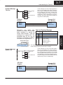
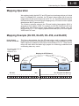
This figure demonstrates how the OP-panel status word is mapped to ladder
program user memory for bit manipulation. In this figure, notice the sixteen bits in the
status register are loaded into the Internal Control Relays C0–C17. These control
relays are used within the ladder logic program for monitoring pushbuttons and
coordinating data entry control.
Understanding
the Features
SP1 (always ON) maps OP
register V2006 to
V40600:C0 –C17.
Mapping the STATUS word
SP1
ON
LD
V2006
OUT
V40600
Internal
Control
Relays
OP-panel
Register
V2006
V40600 =
M+6
C0 – C17
OP–420
15 14 13 12 11 10
Status register
M+6
M+6
9
8
7
6
5
4
3
2
1
0
F4 F3 F2 F1
Entering Programs
We explained earlier that the PLC and OP-panel must exchange data on a bit-level
basis. For DirectLOGIC controllers, the OP-panel status register (M+6) must be
mapped into internal control relays such as C0, C1, etc. This allows direct access to
the Status bit register. You must execute mapping every CPU scan in order to update
data between the OP-panel and PLC.
The following examples assume the OP-panel starting base-register (M+0) is
assigned to word register V2000. For example, the DL105, DL205, D3–350, and
DL405 CPUs have internal control relays starting at register V40600. They are
designated as C0, C1, etc. Mapping updates status data (M+6) into base register
V2006 each PLC scan.
PLC Program User Memory
C17C16C15C14C13 C12 C11 C10 C7 C6 C5 C4 C3 C2 C1 C0
F4 F3 F2 F1