1
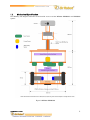
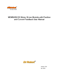
DRK6000/8000 System Specification
DRK6000 Wireless Mobile System
DRK8000 Wireless Mobile Animated Head System
Version: 1.0.5
Feb. 2004
Table of Contents
WiRobot DRK6000/8000 Overview
2
I.1.
Standard Electronics components and Operation Detail
2
I.2.
Mechanical Specification
4
I.3.
Electrical
6
I.3.1. Power ......................................................................................................................................................................6
I.3.2. Communication......................................................................................................................................................6
I.3.3. Electrical Modules ................................................................................................................................................6
I.4.
Other Specification
7
II. Miscellaneous
7
II.1.
Recharging the WiRobot DRK6000/8000 system
7
II.2.
Sensor Location
7
II.3.
Known Issues
7
I.
Related Documents
WiRobot SDK API Reference Manual
WiRobot PMS5005 Sensing and Motion Controller User Manual
WiRobot PMB5010 Multimedia Controller User Manual
Copyright © Dr Robot Inc. 2003.
1
I.
WiRobot DRK6000/8000 Overview
WiRobot is an integrated electronic and software robotic system extended from Dr Robot’s comprehensive
humanoid robot. Each WiRobot development system is designed to provide a user-friendly programming
environment for hobbyists, students and researchers to develop their advanced robot programs and applications
at an affordable cost. The DRK6000/8000 development system includes the respective mechanical structure,
electronic modules as well as the software development kit (SDK). The mechanical structure is already pre-built
and the electronic system is setup with a Multimedia Controller (PMB5010), a Sensing-Motion Controller
(PMS5005) and various peripheral electronic modules. The software component will be installed on a PC and is
responsible to establish a wireless connection and exchange data with the robot. User can develop their own
applications in VC++ or VB using the APIs offered in “WiRobot SDK ActiveX Module” which accesses the sensor
information, sends control command and configures the system setting.
I.1.
Standard Electronics components and Operation Detail
WiRobot DRK6000/8000 Specifications:
On-Board CPUs
Over 120MIPS 16-bit fix-point DSP in total
On-Board Storage
1M x 16-bit words flash, Up to 256K x 16-bit words SRAM
Degree of Freedom
2 x wheel motion, 2 x camera motion (Pan + Tilt) , up to 6 servos and 6 DC motors
DRK6000 DRK8000
Built-in Peripheral Interface
and Modules
8-bit CIF (352 x 288) Color CMOS Camera Module
Audio codec and amplifier module with mic. and speakers
128 x 64 graphic LCD display module
115kbps wireless module
General-purpose PWM DC motor control
DC motors (up to 6)
Servo motors (up to 6)
Quadrature Encoder Inputs
Ultrasonic sensor modules (up to 6)
Potentiometer position feedback sensor (up to 6)
Human sensor module (up to 2)
Infrared range sensor input
Ambient temperature sensor modules
Tilt/acceleration sensor modules
Custom A/D inputs
Digital inputs
Digital outputs
Full duplex serial communication interface (SCI)
Full duplex infrared remote control and communication interface
15 meter indoor
35 meter line of sight
Wireless Operation Range
Power Supply
Operation Time
7.2V Ni-MH 2100mAh
with 2100mAh battery
with 3300mAh battery
Maximum Moving Speed
Approx. 9 meter per minute
Additional/Optional Peripheral Ambient temperature sensor modules
Modules
Tilt/acceleration sensor modules
DC motor
Servo
Ultrasonic sensor module
Potentiometer position feedback sensor
Human sensor module
1 x Smart fast charger
1 x 7.2V Ni-MH 3300mAh
Copyright © Dr Robot Inc. 2003.
X1
X1
X1
X1
X6
X2
X2
X2
X4
X4
X1
X1
X8
X8
X8
X2
X1
1.5hr
2.5hr
X1
X1
X4
X4
X2
X2
X1
X1
X1
X1
X1
X1
X1
X6
X2
X5
X2
X6
X4
X2
X1
X1
X1
X8
X8
X8
X2
X1
1.2hr
2.2hr
X4
X1
X2
X1
X1
2
With this specification, the standard WiRobot DRK series system will come with the following electronic
modules:
Part Number
Name
DRK6000
DRK8000
PMS5005
Robot Sensing and Motion Controller
1
1
PMS5010
1
1
MDM5253
Multimedia Controller
DC Motor Driver Module with Position and Current
Feedback
2
2
MCI3908
Color Image Module With Camera
1
1
DUR5200
Ultrasonic Range Sensor Module
4
6
DHM5150
Pyroelectric Human Motion Sensor Module
1
2
DTA5102
Tilt/Acceleration Sensor Module
0
1
DAT5280
Ambient Temperature Sensor Module
0
1
GP2Y0A21YK
Sharp IR Distance Measuring Sensor Module
1
1
MCB3100
Serial Bluetooth Wireless Module
2
2
MCR3210
RS232 Interface Module
1
1
MCR3210P
RS232 Interface Module with Power Connector
1
1
BAS8100
8 Ohm 1W Speaker
1
1
MAC5310
Audio Codec and Audio Power Amplifier Module
1
1
SAM5247
Uni-directional Electret Microphone
1
1
MIR5538
38kHz Infrared Remote Controller Module
1
1
DIR5538
38kHz Infrared Remote Controller
1
1
CCR2150
RS232 Cross-over Serial Cable
1
1
MGL5128
128x64 Graphic LCD Module
1
1
MRS3302
Rotary Sensor Module
4
4
N/A
Servo
2
5
N/A
DC Motor
2
2
BPN7220
7.2V Ni-MH 2100mAh Battery Pack
1
1
Copyright © Dr Robot Inc. 2003.
3
I.2.
Mechanical Specification
The following two diagrams illustrate the mechanical structure of the WiRobot DRK6000 and DRK8000
system:
Figure I.1 WiRobot DRK6000
Copyright © Dr Robot Inc. 2003.
4
Figure I.2 WiRobot DRK8000
Copyright © Dr Robot Inc. 2003.
5
I.3.
Electrical
I.3.1.
Power
The DRK6000/8000 is powered by a single 7.2V battery pack. This battery pack is connected to both
PMS5005 and PMB5010 through a switch. User can turn on or turn off the system (both PMS5005 and
PMB5010) by pressing the switch.
I.3.2.
Communication
In the DRK6000/8000 system, PMS5005 and PMB5010 are connected together between PMB5010’s
Lower Reach SCI1 and PMS5005’s Upper reach SCI0. A wireless module is placed on PMB5010’s Upper
Reach SCI0 in order to communicate with a PC.
I.3.3.
Electrical Modules
In this system, all electrical modules are located and connected as followed:
Electrical Module
DRK 6000 Location / Setting
DRK 8000 Location / Setting
Ultrasonic #1
Left front
Left front
Ultrasonic #2
Middle front
Middle front
Ultrasonic #3
Right front
Right front
Ultrasonic #4
Middle rear
Right rear
Ultrasonic #5
Middle rear
Ultrasonic #6
Left rear
Human Sensor #1
Middle front
Human Sensor #2
Left front
Right front
Infrared Range Sensor
Under the camera box
Between eyes
Infrared Sensor
Front
Front
Temperature Sensor
Rear
Acceleration and Tilting
Sensor
Inside the robot
Servo #1
To control the left/right movement of the neck
(use channel 1)
To control the up/down movement of the neck
(use channel 1)
Servo #2
To control the up/down movement of the neck
(use channel 2)
To control the left/right movement of the neck
(use channel 2)
Servo #3
To control the mouth (use channel 3)
Servo #4
In between eyes to control the up/down
rotation of the eyes (use channel 5)
Servo #5
In between eyes to control the left/right
rotation of the eyes (use channel 6)
DC Motor #1 with dual
rotary sensors
Left , use channel 1
Left , use channel 1
DC Motor #2 with dual
rotary sensors
Right, use channel 2
Right, use channel 2
LCD Display
Front
Front
Camera
Inside the camera box
Inside left eye
Speaker
Under the camera box
Located near the mouth
Copyright © Dr Robot Inc. 2003.
6
Microphone
Beside the speaker
Near the Infrared range sensor
Please refer to PMS5005 User Manual for details on how to connect different sensors, DC motors, servos, and
LCD display to the system. For camera, speaker and microphone, please refer to PMB5010 User Manual.
I.4.
Other Specification
DRK6000
DRK8000
Weight (including one battery pack)
~2kg
~2.5kg
Recommended Maximum Load
~2.5kg
~2.5kg
II.
Miscellaneous
II.1.
Recharging the WiRobot DRK6000/8000 system
User can simply take out the battery at the lowest deck of the robot to recharge. It will normally take about 20
hours to fully recharge the 2100mAh battery if slow charging is chosen. Fast charge would take about 1-2
hours.
II.2.
Sensor Location
User can change the sensor mounted on the robot to different location to suit his/her needs. As well, user can
add new sensors to the systems by making use of the available I/Os on the Sensing and Motion Controller
(PMS5005). Driver for these I/Os have been pre-programmed, data will be sent to the PC for processing.
II.3.
•
•
•
Known Issues
When the power level is low, the robot’s electrical system will become unstable. User has to monitor the
power level and recharge the battery when it is low.
The initialization of the robot (when powering on) will take about 3-10 seconds.
Please make sure that the robot finished its initialization stage before WiRobot Gateway software (on
PC) starts to connect to the robot. This may lead to failure connection between PC and the robot.
Copyright © Dr Robot Inc. 2003.
7


![[P/N: MCB3101] Class I Serial Bluetooth Wireless](http://vs1.manualzilla.com/store/data/005819698_1-328d04723caa8571829b907b8cc9e0c6-150x150.png)