1
RANGER 8980E
DOWNLOADABLE CONTROL COMMUNICATOR
INSTALLATION MANUAL
TABLE OF CONTENTS
GENERAL DESCRIPTION . . . . . . . . . . . . . . . . . . . . . . . . . . . . . . . . . . . . . . . . . 2
STANDARD AND OPTIONAL PARTS LIST . . . . . . . . . . . . . . . . . . . . . . . . . . . . 2
FEATURE DEFINITIONS . . . . . . . . . . . . . . . . . . . . . . . . . . . . . . . . . . . . . . . . . . 3
TERMINAL DRAWING AND SPECIAL NOTES . . . . . . . . . . . . . . . . . . . . . . . . . 4
TERMINAL & FUSE DESCRIPTION . . . . . . . . . . . . . . . . . . . . . . . . . . . . . . . . . 5
HOW TO PROGRAM THE RANGER 8980E . . . . . . . . . . . . . . . . . . . . . . . . . . . 6
KEYPAD PROGRAMMING EXAMPLES . . . . . . . . . . . . . . . . . . . . . . . . . . . . . . 7
PROGRAMMING PHONE NUMBERS & FORMATS . . . . . . . . . . . . . . . . . . 8 - 9
COMMUNICATOR FORMAT SELECTION GUIDE . . . . . . . . . . . . . . . . . . . . . . 9
OPTIONAL PROGRAMMING INSTRUCTIONS . . . . . . . . . . . . . . . . . . . . 10 - 27
DOWNLOAD PROGRAMMING INSTRUCTIONS . . . . . . . . . . . . . . . . . . . . . . 28
ADDITIONAL COMMENTS ABOUT THE 8980E . . . . . . . . . . . . . . . . . . . . . . . 28
PROGRAMMING WORKSHEETS . . . . . . . . . . . . . . . . . . . . . . . . . . . . . . 29 - 32
APPENDIX 1 - REPORTING SIA FORMAT . . . . . . . . . . . . . . . . . . . . . . . . . . . 33
APPENDIX 2 - REPORTING CONTACT ID . . . . . . . . . . . . . . . . . . . . . . . . . . . 34
UNDERWRITERS LABORATORIES REQUIREMENTS . . . . . . . . . . . . . . . . . 35
LOCAL TELEPHONE COMPANY INTERFACE INFO . . . . . . . . . . . . . . . . . . . 36
SPECIFICATIONS & WARRANTY . . . . . . . . . . . . . . . . . . . . . . . . . . . . . . . . . . 38
CADDX CONTROLS, INC.
GLADEWATER, TEXAS
800-727-2339
RANGER 8980E
INSTALLATION MANUAL
General Description
The Caddx Ranger 8980E is a versatile 8 zone up/downloadable security control with a built-in digital
communicator. Its microcomputer design gives some of the most versatile, yet easy-to-use features
available for most security applications today. Each of the eight zones can be programmed to be one of ten
different types including 24-Hour, Interior Follower, and Day zone. Each zone is individually annunciated
and can be bypassed from the keypad. See page ? for a description of all zone types. Read the User’s
Manual before you begin the installation for the best overall description of how the Ranger 8980E functions.
After installation of the security system, complete the information on page 1 of the User’s Manual and
explain the system operation to all security system owners/operators.
Standard Parts List
The Ranger 8980E is shipped with the parts listed below.
QUANTITY
PARTS DESCRIPTION
PART #
1
MASTER CONTROL PANEL
8985E
1
REMOTE KEYPAD
1
16.5VAC 25VA TRANSFORMER
T-1625
10
3.3K ½ WATT E.O.L. RESISTORS
EOL-33
1
INSTALLATION MANUAL
IM-8980E
1
USER’S MANUAL
OM-8980E
8981
Optional Parts List
The following parts are available for use with the Ranger 8980E.
OPTIONAL PARTS DESCRIPTION
PART #
REMOTE KEYPAD *
8982
LCD ALPHA NUMERIC KEYPAD *
9050
DOWNLOADING SOFTWARE *
DL-900
PROGRAMMER WITH DIGITAL NUMERIC DISPLAY
12VDC 6AH BATTERY
8950
B-1260
END OF LINE DEVICE FOR U.L. 985 FIRE ZONE
* These parts have not been tested by Underwriters Laboratories.
2
EOL-34UL
FEATURE DEFINITIONS
INTERNAL EVENT LOG - Up to 80 events can be stored in memory along with the date and time of the event.
These events can later be viewed through downloading.
TELEPHONE LINE MONITOR - The Ranger 8980E has a telephone line monitor that monitors the voltage and
current of the telephone line for a detection of a faulted phone line. See locations 194 & 195, page 23.
KEYSWITCH ARMING - Keyswitch arming/disarming can be accomplished by using the remote arming input on
the PC board, and the auxiliary outputs. It is not necessary to waste a hardwire zone to accommodate Keyswitch
arming/disarming.
SECONDARY EXIT DELAY - Used most often for garage doors, this zone type is a second entry/exit delay that
has its own delay times, independent of the standard entry/exit delay zone.
BUILT IN SIREN DRIVER - The Ranger 8980E has a built-in 112db siren driver. When desired, this built-in driver
can be easily converted to a 1 amp voltage output through programming. See location 132, page 15.
QUICK ARM FEATURE - The Ranger 8980E has a one button "Quick Arm" code which can be used to arm the
system by pressing one digit at the keypad. The "Quick Arm" digit is programmed in location 139 on page 16.
GROUP BYPASS - A designated group of zones can be programmed to bypass by pressing the [U][9][U] keys
before arming. In order to bypass a group of designated zones, you must press This feature is enabled in
Locations 244-251: Assigning Special Characteristics For Zones, on page 27.
ENTRY-GUARD - This unique low level arming mode has been developed to reduce the most common source
of false alarms. When armed in this mode, the opening of any zones designated as "Entry Guard zones" will
initiate the keypad sounder and start a delay (see locations 244-251) before creating an alarm. This arming mode
will encourage system owners to use their system more frequently when the premises is occupied.
CHIME - If so programmed, this feature can be turned on and off by entering the first digit of the Master code.
When the system is in the disarmed state, the opening of selected zones will create a one second tone through
the keypad sounder. This lowest level of security can be enabled by zone on page 23, in locations 186-193:
FORCE ARMING - When enabled in location 197, the Ranger 8980E can be armed with zones violated, lacking
a green "Ready" light on the keypad. Under this condition, all zones that are not secure at the end of the exit delay
will become bypassed. All zones that become secured before the end of the exit delay will become active in the
system.
AUTOMATIC ARMING - The Ranger 8980E can be programmed to Automatically Arm at a predesignated time
of day, if it has not already been armed. See location 202, page 24.
DUAL/SPLIT REPORTING - The Ranger 8980E can be programmed for dual and/or split reporting.
AUTOMATIC BYPASS/INSTANT ARMING - When enabled, the control panel can automatically bypass interior
follower zones if an exit is not detected during the delay time, and delayed zones can be made instant. See
location 131, on page 16 of this manual for the different combinations of programming this feature.
DYNAMIC BATTERY TEST - When enabled in location 203, the Ranger 8980E can be programmed to perform
a dynamic battery test for a selected duration, at 6:00 AM.
FIRE ALARM VERIFICATION - When enabled in location 143, the Ranger 8980E has the ability to verify a Fire
alarm by requiring more than one trip on a smoke detector before creating an alarm.
Five seconds after pressing the [0] key, the keypad will annunciate “Freeze Frame” alarm
ALARM HISTORY history. The zone LED’s will indicate which zone(s) caused the last alarm, regardless of the number of times the
Ranger 8980E has been armed or disarmed since that alarm. It annunciates by blinking the zone LED(s) that
caused the alarm, and lighting steady those that were bypassed when that alarm occurred. The annunciation will
continue for 5 seconds. Alarm History is erased when the Ranger 8980E is put into the program mode. A
burglary zone that has been bypassed due to “Swinger Shutdown” will alternate between continuous and blinking.
3
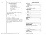
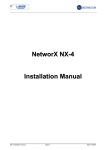
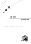
TERMINAL DRAWING & SPECIAL NOTES
4
TERMINAL DESCRIPTION
TERMINAL
1-4
DESCRIPTION
Programmable Auxiliary Output Terminals
5
Connect one side of zone 1 loop. The other side of loop to common terminal 6. Open
or short causes alarm.
6
Common (-) Terminal
7
Connect one side of zone 2 loop. The other side of loop to common terminal 6. Open
or short causes alarm.
8-16
See Terminal Drawing and repeat the above sequence for zones 3-8 .
17,18,19,20
Connect keypad wires as follows; yellow to terminal 17, green to terminal 18, black to
terminal 19, red to terminal 20. 200 ft. maximum run with 22 gauge wire, 500 ft.
maximum run with 18 gauge wire. Home run cable to each keypad.
21(-)& 22(+)
Siren driver output to speaker(s), (speaker rating should be 15 watt at 8 or 16 ohm, or
30/40 watt at 4, 8, or 16 ohms). If siren driver disable is selected in location 132, output
becomes voltage output, 12VDC, 1 Amp maximum load.
23(-)& 24(+)
Smoke detector power 12VDC, 100 mA maximum (For those jurisdictions which allow
the Priority zone to be used with smoke detectors.)
25(-)& 26(+)
Auxiliary power, regulated 12VDC, 500 mA maximum.
27
Earth Ground, connect to a cold water pipe or 6 to 10 foot driven rod.
28 & 29
AC input, connect a 16.5V 25 VA, Class II U.L. approved transformer (included).
T1
(T1) House Telephone Tip (brown)
T
(T) Telephone Tip (green)
R
(R) Telephone Ring (red)
R1
(R1) House Telephone Ring (gray)
Battery Leads
Battery leads Standby battery leads black(-) and red(+) connect to a 12VDC lead acid
rechargeable battery. Do not connect to a dry cell battery.
FUSE DESCRIPTION
FUSE #
DESCRIPTION
F2
KEYPAD (1 AMP)
F3
SPEAKER / BELL (2 AMP)
F4
AUXILIARY / SMOKE DETECTOR POWER (1 AMP)
5
PROGRAMMING
The Ranger 8980E can be placed into the "Program" mode by use of the 9075 Smart
Programmer, the 8950 programmer, or for Keypad programming, by utilizing the 9050 LCD
Keypad or the 8601 LED Keypad. These methods are described below:
Using a Programmer
Plug the optional 8950 Programmer into the 4-pin male outlet marked “PROGRAMMER” on the Ranger
8980E PC Board and the control will enter the program mode. The 8950 will program locations “000"
through “255" of the 8980E control (See using the LED Keypad below.) When using a 9075 Smart
Programmer, please refer to the 9075 Manual.
Using The LCD Keypad
The most straightforward method of Keypad programming is to utilize the 9050 LCD Keypad in the
programming mode. To access the programming mode enter [C]-[0]-[0], followed by the four digit "Go
To Program" access code which is factory default [9]-[0]-[5]-[0] (this code can be reprogrammed), and
follow the Keypad prompts. (See using the LED Keypad below.)
Using The LED Keypad
The 8980E can also be programmed by the standard binary method of Keypad programming described
below. When the 8601 LED Keypad is used for programming, enter the factory default four digit "Go
To Program" access code of [9]-[7]-[1]-[3]. NOTE: The 8980E must be disarmed to gain access to
programming with this code. After entry of this code, the 8980E will be in the "Program" mode, and the
yellow LED's will display the data in location 000. The data is displayed using a Binary system. With this
system the yellow zone 1 LED equals "1" when illuminated. The zone 2 LED equals "2" when
illuminated. The zone 3 LED equals "4" when illuminated. The zone 4 LED equals "8" when illuminated.
Thus if the data in location 000 is "9", the LED for zone 1 (=1) and zone 4 (=8) would be illuminated. By
adding the two values together, (1+8=9) you would determine that the data in location 000 is "9". If the
data in location 000 is "6", the LEDs for zone 2 (=2) and zone 3 (=4) would be added (2+4=6) indicating
the data in that location to be "6". If no LED's are illuminated, the location contains a "0". To advance
from location 000 through 255, press the [#] key. To go to a specific location, press the location number
followed by the [#] key. The yellow LED's will then display the data in that location. Data is changed by
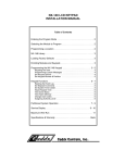
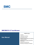
entering a number 0 to 15 followed by [U] (U = data enter). Review the examples in figure 1 on the
following page.
Important Function Codes
[9]-[1]-[0]-[#] When in the program mode, this function code can be used to write original factory
default codes into the 8980E.
[9]-[2]-[0]-[#] When in the program mode (after data has been entered into locations 000-255), you
must enter [9]-[2]-[0]-[#] to permanently load the information into the EEPROM. IF THIS
STEP IS NOT TAKEN, THE DATA IN THE EEPROM WILL NOT CHANGE, AND THE
RANGER 8980E WILL NOT CHANGE CHARACTERISTICS.
[9]-[3]-[0]-[#] This function code is used to exit the programming mode after it was accessed via the
Keypad.
[2]-[3]-[0]-[#] This function code is used to exit the programming mode after it was accessed via the
9050 LCD Keypad.
6
7
PAGES 8 & 9 DESCRIBE ALL THE LOCATIONS WHICH MUST BE PROGRAMMED FOR THE
RANGER 8980E TO FUNCTION AND REPORT TO A CENTRAL STATION. OTHER OPTIONS
MAY BE SELECTED BY FOLLOWING THE ADDITIONAL PROGRAMMING INSTRUCTIONS.
LOCATIONS 032-047: PROGRAMMING THE PRIMARY TELEPHONE NUMBER
The primary telephone number is programmed in successive locations beginning with location 032. Any zero (0)
within the telephone number, must be programmed as a "10". A "0" indicates the end of the phone number. Delays
of four seconds can be programmed at any point in the phone number by programming a "13" in the appropriate
location. If tone dialing is desired, program a "15" in the location where tone dialing should begin. If the entire number
should be tone dialing, program a "15" in location 032. To dial a U, program an “11". To dial a #, program a “12".
When using split reporting, the primary number always takes priority over the secondary telephone number.
LOCATIONS 048-051: PROGRAMMING THE ACCOUNT CODE FOR THE PRIMARY PHONE NUMBER
The account code sent when the PRIMARY phone number is dialed is programmed in locations 048-051. Any zero
(0) within the account code must be programmed as a "10", and the communicator will report a zero (0). If the
account code is three digits long, use locations 048,049, and 050, and program a "0" in location 051 to indicate the
end of the account code.
LOCATION 052: PROGRAMMING COMMUNICATOR FORMAT FOR THE PRIMARY PHONE NUMBER
Location 052 contains the communicator format used to transmit to the receiver connected to the primary phone
number. Consult the instructions for your central station receiver to determine which format is compatible. To select
Ademco/Silent Knight Fast, program a "2" in location 052. Radionics 1800HZ/2300HZ Fast w/Parity and Hex
Capability requires a "9" in this location. For a Pager format, program a "15" in this location, along with the
appropriate data in locations 208 and 209. If you need another format, choose from those listed in the format table
located on the following page, and program the data in location 052. If this location contains a "0", the built-in
communicator will be disabled, and the Ranger 8980E will function as a local only control.
LOCATION 053: DISABLING THE SECONDARY TELEPHONE NUMBER AS A BACKUP
Location 053 is used to disable the secondary phone number as a "backup". This feature can be used with split
reporting (locations 176-177) to prevent a report from going to the secondary telephone number after unsuccessful
attempts to the primary phone number. Programming a "0" will make the secondary phone number backup the
primary, and the primary phone number backup the secondary. Programming a "3" will make the control alternate
from the primary to the secondary number (2 calls each) for the number of attempts programmed in location 134.
If location 053 contains a "1", only the primary phone number will be called.
LOCATIONS 054-069: PROGRAMMING THE SECONDARY TELEPHONE NUMBER
Locations 054-069 contain the secondary telephone number. This number allows certain communicator reports to
go to another number, or to cause the communicator to dial a second number if the primary number does not respond
after the number of attempts programmed in location 134 have been tried unsuccessfully. The same number of
attempts are made with the back-up number. Tone dialing and delay instructions are the same as for the primary
number.
LOCATIONS 070-073: PROGRAMMING THE ACCOUNT CODE FOR THE SECONDARY PHONE NUMBER
Locations 070-073 contain the account code for the secondary phone number. Any zero (0) within the account code
must be programmed as a "10", and the communicator will report a zero (0).If the account code is three digits long,
use locations 070, 071, and 072, and program a "0" in location 073 to indicate the end of the account code. If these
locations are left blank, the account code in locations 048-051 will be reported.
8
LOCATION 074: PROGRAMMING COMMUNICATOR FORMAT FOR THE SECONDARY TELEPHONE NUMBER
Location 074 contains the communicator format for the secondary phone number. Consult the instructions for your
central station receiver to determine which format is compatible. To select Ademco/Silent Knight Fast, program
a "2" in this location. Radionics 1800HZ/2300HZ Fast with Parity and Hex Capability requires a "9" in this location.
For a Pager format, program a "15" in this location, along with the appropriate data in locations 208 and 209. If you
need another format, choose from those listed in the format table below, and program the appropriate data in this
location. If location 074 is "0", the format programmed in location 052 will be used.
DATA
FORMAT
DESCRIPTION
"0"
LOCAL ONLY
THE COMMUNICATOR IS DISABLED
"1"
UNIVERSAL 4 + 2
1800HZ TRANSMIT 2300HZ HANDSHAKE DOUBLE
ROUND PARITY 40 PPS.
"2"
ADEMCO/SILENT KNIGHT FAST
1900HZ TRANSMIT 1400HZ HANDSHAKE DOUBLE
ROUND PARITY 20 PPS.
"3"
CADDX MODEM
PROPRIETARY
"4"
SESCOA SUPERFAST
1800HZ TRANSMIT 2300HZ 4/2
"5"
EXTENDED RADIONICS SLOW
1800HZ TRANSMIT 2300HZ HANDSHAKE DOUBLE
ROUND PARITY 20 PPS EXTENDED HEX CAPABILITY
"6"
EXTENDED RADIONICS SLOW
1800HZ TRANSMIT 1400HZ HANDSHAKE DOUBLE
ROUND PARITY 20 PPS EXTENDED HEX CAPABILITY
"7"
EXTENDED RADIONICS FAST
1800HZ TRANSMIT 2300HZ HANDSHAKE DOUBLE
ROUND PARITY 40 PPS EXTENDED HEX CAPABILITY
"8"
EXTENDED RADIONICS FAST
1800HZ TRANSMIT 1400HZ HANDSHAKE DOUBLE
ROUND PARITY 40 PPS EXTENDED HEX CAPABILITY
"9"
EXTENDED RADIONICS FAST
WITH PARITY
1800HZ TRANSMIT 2300HZ HANDSHAKE SINGLE
ROUND W/PARITY 40 PPS EXTENDED HEX
CAPABILITY
A="10"
EXTENDED RADIONICS FAST
WITH PARITY
1800HZ TRANSMIT 1400HZ HANDSHAKE SINGLE
ROUND W/PARITY 40 PPS EXTENDED HEX
CAPABILITY
B="11"
ADEMCO 4 + 2 EXPRESS
DTMF
C="12"
SILENT KNIGHT 4 + 2
1900HZ TRANSMIT 1400 HANDSHAKE DOUBLE
ROUND 20PPS
D="13"
ADEMCO CONTACT ID
DTMF
(SEE APPENDIX 2)
E="14"
SIA
FSK
(SEE APPENDIX 1)
F="15"
PAGER/CUSTOM FORMAT
SEE OVER-RIDE LOCATIONS 182, 183, 208, 209.
LOCATIONS 000-003: PROGRAMMING THE MASTER ARM/DISARM CODE
Locations 000-003 contain master arm/disarm code (user number 1). Location 000 contains the first digit of the
code; location 003 contains the fourth digit of the code. THE CODE MUST CONTAIN FOUR (4) DIGITS. The
master code can then be used in the run mode to enter arm/disarm codes 1-7. The factory default code is [1]-[2][3]-[4]. NOTE: User codes 8 thru 14 can only be accessed from the installers programming level in locations 212239.
9
LOCATIONS 004-023: PROGRAMMING THE ARM/DISARM CODE FOR USERS 2 THRU 6
Locations 004-023 contain the arm/disarm codes for user numbers 2 thru 6. Location 004 contains the first digit
of the code #2, and location 007 contains the fourth digit of code #2. THESE CODES MUST CONTAIN FOUR
(4) DIGITS. To disable a code, PROGRAM a "15" as the first digit of the code. These codes can be changed in
the RUN mode using the master code. User codes 8 thru 14 (locations 212-239) can be accessed from the
program mode only.
LOCATIONS 024-027: PROGRAMMING THE DURESS CODE OR USER 7
Locations 024-027 contain the arm/disarm code for Duress or for user number 7. Duress capability is enabled
by programming a communicator code in locations 086-087. If locations 086-087 are left unprogrammed, user
number 7 will act as a standard user code. If the maintenance code option is selected in location 167, locations
024-027 should not be programmed.
LOCATIONS 028-031: PROGRAMMING THE "GO TO PROGRAM" ACCESS CODE
Locations 028-031 contain the "Go To Program" access code. Location 028 contains the first digit of the code and
location 031 contains the fourth digit of the code. THE CODE MUST CONTAIN FOUR (4) DIGITS. With the
Ranger 8980E disarmed, the "Go To Program" access code can be used to enter the program mode. To disable
the "Go To Program" access code, program a "15" in location 028. The factory default setting is [9][7][1][3].
LOCATIONS 032-074: SEE PAGES 8 & 9
LOCATION 075: PROGRAMMING THE ENTRY DELAY TIME
Location 075 contains the number of 10 second increments in the entry delay. The entry delay can be
programmed in 10 second increments from 10 to 150 seconds ("1" = 10 seconds through "15" = 150 seconds).
For example, programming a "2" in this location will produce an entry delay of 20 seconds. (Note: A "0" entry is
treated as 0 seconds). Programming a "6" in this location will produce an entry delay of 60 seconds. Factory
default is 30 seconds.
LOCATION 076: PROGRAMMING THE EXIT DELAY TIME
Location 076 contains the number of 10 second increments in the exit delay. The exit delay can be programmed
in 10 second increments from 10 to 150 seconds ("1" = 10 seconds through "15" =150 seconds). For example,
programming a "2" in this location will produce an exit delay of 20 seconds. (Note: A "0" entry is treated as 0
seconds). Programming a "6" in this location will produce an exit delay of 60 seconds. Factory default is 60
seconds.
LOCATION 077: PROGRAMMING THE SIREN SHUTDOWN/RECYCLE TIMEOUT
Location 077 contains the number of 2 minute increments in the automatic cutoff time. The automatic cutoff time
can be programmed in 2 minute increments from 2 to 30 minutes ("1" = 2 min thru "15" = 30 min). For example,
programming a "2" in this location will produce an automatic cutoff time of 4 minutes. Programming a "6" in this
location will produce an automatic cutoff time of 12 minutes.
LOCATIONS 078-085: PROGRAMMING THE ZONE TYPES
Locations 078 through 085 contain a number identifying the characteristics of each of the 8 zones. Location 078
corresponds to zone 1 and location 085 corresponds to zone 8. Each zone will factory default according to the
programming worksheet. To program zone characteristics other than the default values, program a number from
"1" to "10" based on the zone types available in the chart on the following page.
10
DATA
AVAILABLE ZONE TYPES
"1"
DAY ZONE - When armed, a trip produces an instant alarm. When disarmed, a trip activates the keypad
sounder.
"2"
24 HOUR - A trip on a 24 Hour zone produces an instant alarm when armed or disarmed.
"3"
ENTRY/EXIT - A trip will start entry delay. The lack of a trip during exit delay will enable the Automatic Bypass
or Instant mode if so programmed.
"4"
INTERIOR DELAY - A trip on Interior Delay zone will initiate an entry delay. It will be ignored during exit delay
and when disarmed .
"5"
INTERIOR FOLLOWER - Interior zone that follows the delay zones. It is instant during non-delay times. It can
be bypassed before arming, or by allowing it to automatically be bypassed in the Automatic Bypass/Instant
mode if so programmed.
"6"
INSTANT - Produces an instant alarm if tripped when armed. Ignored when disarmed.
"7"
24 HOUR SILENT - A trip on a 24 hour silent zone will communicate to the central station when the Ranger
8980E is armed or disarmed.
"8"
FIRE (PRIORITY WHEN AHJ HAS NOT APPROVED) - A short on a FIRE zone (non-bypassable) will
communicate to the central station when the Ranger 8980E is armed or disarmed. An open will create a
Trouble condition. Keypad LED will be steady for FIRE, and flashing for Trouble.
"9"
SECONDARY DELAY - A secondary delay zone works like an entry/exit delay zone but has its own
independent delay time (see locations 178-179).
"10"
SUPERVISED 24 HOUR SILENT - A trip on a Supervised 24 hour silent zone will communicate to the central
station when the 8980E is armed/ disarmed, and give LED indication of the zone(s) faulted.
NOTE: WHEN PROGRAMMING THE FOLLOWING COMMUNICATOR CODES,
A "10" MUST BE PROGRAMMED IN ORDER TO REPORT A ZERO (0).
LOCATION 086-087: PROGRAMMING THE RANGER 8980E FOR DURESS CODE CAPABILITY
The Ranger 8980E has the ability to report a duress code when the system is armed or disarmed with user code
number 7 and a duress communicator code is programmed in locations 086-087. If both locations are "0", the
duress capability is disabled and user code number 7 can only be used as a standard arm/disarm code. Location
086 contains the standard digit, and location 087 contains the extended digit. When using 4+2 format, the number
programmed in location 086 is sent as the "ones" digit. The "tens" digit is programmed in location 087. NOTE:
ENABLING THE MAINTENANCE CODE FEATURE IN LOCATION 167 WILL AUTOMATICALLY DISABLE THE
DURESS FEATURE.
LOCATION 088-089: PROGRAMMING FOR AUXILIARY 1, [1] & [3] DOUBLE KEYPRESS
The Ranger 8980E has the ability to report an Auxiliary 1 code and activate the Priority siren each time the [1]
and [3] keys are pressed simultaneously on the keypad. The desired reporting code is programmed in locations
088-089. If both locations are "0", the Auxiliary 1 double keypress is disabled. Location 088 contains the standard
digit, and location 089 contains the extended digit. When using a 4+2 format, the number programmed in location
088 is sent
as the "ones" digit. The "tens" digit is programmed in location 089. If activated, the siren can be silenced by
entering any arm/disarm code.
LOCATION 090-091: PROGRAMMING FOR AUXILIARY 2, [4] & [6] DOUBLE KEYPRESS
The Ranger 8980E has the ability to report an Auxiliary 2 code and activate the pulsing buzzer each time the [4]
and [6] keys are pressed simultaneously on the keypad. The desired Auxiliary 2 code is programmed in locations
090-091. If both locations are "0", the Auxiliary 2 double keypress is disabled. Location 090 contains the standard
digit, and location 091 contains the extended digit. When using 4+2 format, the number programmed in location
090 is sent as the "ones" digit. The "tens" digit is programmed in location 091. If activated, the keypad sounder
can be silenced by entering any Arm/Disarm code.
11
LOCATION 092-093: PROGRAMMING FOR KEYPAD PANIC, [U] & [#] DOUBLE KEYPRESS
The Ranger 8980E has the ability to report a Keypad panic code and activate the Burg siren each time the [U]
and [#] keys are pressed simultaneously on the keypad. The desired Keypad panic code is programmed in
locations 092-093. If both locations are "0", the Keypad panic double keypress is disabled. Location 092 contains
the standard digit, and location 093 contains the extended digit. When using 4+2 format, the number programmed
in location 092 is sent as the "ones" digit. The "tens" digit is programmed in location 093. If activated, the siren
can be silenced by entering any Arm/Disarm code.
LOCATION 094-095: PROGRAMMING THE TAMPER FEATURE
The Ranger 8980E has an optional tamper feature that, when enabled, will lock out the keypads for 1 minute if
30 random keypresses are made without producing a valid code. The desired tamper code should be
programmed in locations 094-095. If the control is not programmed for local only, the tamper will be
communicated. If both locations are "0", the tamper feature will not be enabled or reported. Location 094 contains
the standard digit, and location 095 contains the extended digit. When using 4+2 format, the number programmed
in location 094 is sent as the "ones" digit. The "tens" digit is programmed in location 095.
LOCATION 096-097: PROGRAMMING TO REPORT DOWNLOADING COMPLETE
Locations 096-097 contain the communicator report sent each time a download session has been completed. The
report will come in after a disconnect has been made from a downloading session. Location 096 contains the
standard communicator code, and location 097 contains the extended communicator code. When using a 4+2
format, the number programmed in location 096 is sent as the "ones" digit. The number programmed in location
097 is sent as the "tens" digit. When using an extended format, the extended report will be sent if location 097
contains a number other than "0". If locations 096-097 are "0", this report is disabled.
LOCATION 098-099: PROGRAMMING FOR AUTOTEST REPORTS
The Ranger 8980E has the ability to send autotest reports at intervals from 1 to 15 days. Locations 098-099
contain the communicator codes sent for autotest. Location 098 contains the standard communicator code, and
location 099 contains the extended communicator code. When using a 4+2 format, the number programmed in
location 098 is sent as the "ones" digit. The number programmed in location 099 is sent as the "tens" digit. When
using an extended format, the extended report will be sent if location 099 contains a number other than "0". If
locations 098-099 are "0", autotest is disabled. (NOTE: WHEN USING AUTOTEST, LOCATIONS 152-166 MUST
BE PROGRAMMED.)
LOCATION 100-101: PROGRAMMING TO REPORT FAILURE TO COMMUNICATE
The 8980E has the ability to communicate each time communication is re-established after a signal has been
unable to report. The data that failed to communicate will not be sent, but can be recovered from the log. The
desired "Failure To Communicate" code is programmed in locations 100-101. If both locations are "0", "Failure
To Communicate" will not be reported. Location 100 contains the standard digit, and location 101 contains the
extended digit. When using 4 + 2 format, the number programmed in location 100 is sent as the "ones" digit. The
"tens" digit is programmed in location 101.
LOCATION 102: PROGRAMMING TO REPORT CLOSINGS
The Ranger 8980E has the ability to report a closing code each time the control is armed. The desired closing code
is programmed in location 102. If this location contains a "0", closings will not be reported. When using 4+2 format,
the number programmed in this location is sent as the "tens" digit. The "ones" digit is automatically the man number.
When using the remote arming input, the man number is 1. When using a one button "Quick Arm" code the man
number is 1. The closing report will not be initiated until the end of the exit delay. When using automatic arm, the
man number is 9.
LOCATION 103: PROGRAMMING TO REPORT OPENINGS
The Ranger 8980E has the ability to report an opening code each time the control is disarmed. The desired opening
code is programmed in location 103. If this location contains a "0", openings will not be reported. When using 4+2
format, the number programmed in this location is sent as the"tens" digit. The "ones" digit is automatically the man
number. When using the remote arming input, the man number is 1.
12
LOCATION 104-105: PROGRAMMING THE COMMUNICATOR CODE FOR ZONE 1
Locations 104-105 contain the communicator code to be reported each time zone 1 creates an alarm. Location 104
contains the standard digit, and location 105 contains the extended digit. When using 4+2 format, the number
programmed in location 104 is sent as the "ones" digit. The "tens" digit is programmed in location 105.
LOCATION 106-107: PROGRAMMING THE COMMUNICATOR CODE FOR ZONE 2
Locations 106-107 contain the communicator code to be reported each time zone 2 creates an alarm. Location 106
contains the standard digit, and location 107 contains the extended digit. When using 4+2 format, the number
programmed in location 106 is sent as the "ones" digit. The "tens" digit is programmed in location 107.
LOCATION 108-109: PROGRAMMING THE COMMUNICATOR CODE FOR ZONE 3
Locations 108-109 contain the communicator code to be reported each time zone 3 creates an alarm. Location 108
contains the standard digit, and location 109 contains the extended digit. When using 4+2 format, the number
programmed in location 108 is sent as the "ones" digit. The "tens" digit is programmed in location 109.
LOCATION 110-111: PROGRAMMING THE COMMUNICATOR CODE FOR ZONE 4
Locations 110-111 contain the communicator code to be reported each time zone 4 creates an alarm. Location 110
contains the standard digit, and location 111 contains the extended digit. When using 4+2 format, the number
programmed in location 110 is sent as the "ones" digit. The "tens" digit is programmed in location 111.
LOCATION 112-113: PROGRAMMING THE COMMUNICATOR CODE FOR ZONE 5
Locations 112-113 contain the communicator code to be reported each time zone 5 creates an alarm. Location 112
contains the standard digit, and location 113 contains the extended digit. When using 4+2 format, the number
programmed in location 112 is sent as the "ones" digit. The "tens" digit is programmed in location 113.
LOCATION 114-115: PROGRAMMING THE COMMUNICATOR CODE FOR ZONE 6
Locations 114-115 contain the communicator code to be reported each time zone 6 creates an alarm. Location 114
contains the standard digit, and location 115 contains the extended digit. When using 4+2 format, the number
programmed in location 114 is sent as the "ones" digit. The "tens" digit is programmed in location 115.
LOCATION 116-117: PROGRAMMING THE COMMUNICATOR CODE FOR ZONE 7
Locations 116-117 contain the communicator code to be reported each time zone 7 creates an alarm. Location 116
contains the standard digit, and location 117 contains the extended digit. When using 4+2 format, the number
programmed in location 116 is sent as the "ones" digit. The "tens" digit is programmed in location 117.
LOCATION 118-119: PROGRAMMING THE COMMUNICATOR CODE FOR ZONE 8
Locations 118-119 contain the communicator code to be reported each time zone 8 creates an alarm. Location 118
contains the standard digit, and location 119 contains the extended digit. When using 4+2 format, the number
programmed in location 118 is sent as the "ones" digit. The "tens" digit is programmed in location 119.
LOCATION 120-121: PROGRAMMING TO REPORT AC POWER LOSS
The Ranger 8980E has the ability to report an AC power failure code when AC power is lost. This report can be
immediate, or delayed depending on the information programmed in location 150 AC POWER LOSS DELAY. The
desired AC failure mode should be programmed in locations 120-121. If both locations are "0", AC power failures will
not be reported. Location 120 contains the standard digit, and location 121 contains the extended digit. When using
4+2 format, the number programmed in location 120 is sent as the "ones" digit. The "tens" digit is programmed in
location 121.
13
LOCATION 122-123: PROGRAMMING TO REPORT LOW BATTERY
The Ranger 8980E can perform a dynamic battery test and report a low battery code when the battery has
discharged down to 10.3 volts. The desired low battery code is programmed in locations 122-123. If both locations
are "0", low battery will not be reported. Location 122 contains the standard digit, and location 123 contains the
extended digit. When using 4+2 format, the number programmed in location 122 is sent as the "ones" digit. The "tens"
digit is programmed in location 123.
LOCATION 124: PROGRAMMING FOR PRIORITY ZONE TROUBLE REPORTING
The Ranger 8980E has the ability to report a trouble code each time a Priority zone opens. The desired trouble code
is programmed in location 124. If this location contains a "0", the Priority Trouble will not be reported.
LOCATION 125: PROGRAMMING FOR ZONE BYPASS REPORTING
The Ranger 8980E has the ability to report a bypass on zones 1-8. The desired bypass code is programmed in
location 125. If this location contains a "0", zone bypass will not be reported. When using 4+2 format, the number
programmed in this location is sent as the "tens" digit. The "ones" digit is the zone communicator code. The bypass
will be reported at the end of the exit delay for non-24 hour zones. 24 hour zones will report a bypass immediately.
When a bypass is removed, a restore will be reported if "Restore" is enabled in location 126.
LOCATION 126: PROGRAMMING THE COMMUNICATOR CODE FOR RESTORAL
Location 126 contains the communicator code that will be sent for restoral of a zone. If this location contains a "0",
no restorals will be reported. If a restoral code is programmed and an extended format is selected, the restorals will
be reported by zone. If a restoral code is programmed and an extended format is not selected, a restoral code will
be sent when all of the previously reported conditions have restored. When using 4+2 format, the number
programmed in this location is sent as the first, or "tens" digit. The second, or "ones" digit will be the "ones" digit of
the zone or condition that restored.
LOCATION 127: PROGRAMMING THE COMMUNICATOR CODE FOR CANCEL (EXCEPTION OPENING)
Location 127 contains the communicator code that will be sent for cancel. The cancel code programmed in this
location will be sent if an arm/disarm code is entered after a trip on zones 1 through 8 has been reported (excluding
24 hour zones). After a cancel has been reported, no loop restorals will be transmitted on non-24 Hour zones. If this
location contains a "0", cancel is disabled. When using 4+2 format, the number programmed in this location is sent
as the "tens" digit. The "ones" digit is the man number of the person that canceled. When using a remote arming
input, the man number is 1.
LOCATION 128: PROGRAMMING THE COMMUNICATOR TO ABORT
Location 128 is used to enable the communicator abort. The number programmed in this location will be the number
of two-second increments the 8980E will delay before attempting to communicate an alarm on a non-24 hour zone.
If this location contains a "0", the Ranger 8980E will not abort any reports.
LOCATION 129: PROGRAMMING FOR SILENT PANIC/HOLD-UP
Location 129 is used to silence the audible output for a panic/hold-up alarm. Programming a "1" in this location will
silence the audible output during a panic/hold-up alarm. If this location contains a "0", the Ranger 8980E will have
an audible panic/hold-up output. Program a “2" to silence Keypad Sounder during alarm.
LOCATION 130: ENABLING THE SWINGER SHUTDOWN
Location 130 is used to enable the burglary zone swinger shutdown. The number programmed in this location, will
determine the number of trips the Ranger 8980E will allow, before bypassing all burglary zones (1-8) which have
tripped during an arming cycle. The bypassed zones will not report trips to a central station, and the local siren or
bell will not sound for these zones. A zone trip will not be added to the number count until after the zone has tripped
more than once. If this location contains a "0", this feature is disabled. A zone which has been bypassed by this
feature will be reported if bypass reporting is enabled in location 125. NOTE: THIS FEATURE CANNOT BE
ENABLED FOR U.L. INSTALLATIONS.
14
LOCATION 131: AUTOMATIC BYPASS / INSTANT ARMING
Location 131 is used to enable automatic "Instant Arming". Programming a "1" in this location will cause the control
to automatically enter the "Instant" mode and bypass interior follower zones if a fault is not detected on an entry/exit
zone during the exit delay. Programming a "3" in this location (Automatic Bypass), will cause the interior follower
zones to become bypassed if a fault is not detected on an entry/exit zone, yet will not change the status of the
entry/exit zone. Programming a “4" in this location will enable Entry Guard (see page 27 for a complete description).
If this location contains a "0", these features are disabled. Pressing the [U] key when the system is armed, will cause
the "Instant" light to toggle. When the "Instant" light is on, the entry/exit zone is instant; when off, the entry/exit zone
is delayed. The [U] key will toggle the "Instant" mode regardless of the programming data in this location. See
location 141 "Special Keypad Functions" to further enhance these features.
LOCATION 132: SIREN DRIVER OR VOLTAGE OUTPUT / LAST CHANCE TO EXIT WARNING
The built-in siren driver has a steady sound (for Priority zone type), and a yelp sound (for Burglary and Panic).
Factory default is "0", enabling this feature. If the built-in siren driver is NOT to be used, take the following procedure.
First, remove the jumper marked voltage/siren on the PC board. Next, program a "1" in location 132. Finally, replace
the jumper in the voltage position. Terminals 21 & 22 will now output 1 Amp at 12VDC. NOTE: Ten seconds prior to
the end of the exit delay the keypad will sound the "Last Chance To Exit Warning" (one long beep followed by three
short beeps). To disable the "Last Chance To Exit Warning", add 4 to the Siren Driver/Voltage Output data selected
above and program the sum (0 + 4 = "4" or 1 + 4 = "5") in this location.
LOCATION 133: L.E.D. EXTINGUISH FEATURE
Keypad LEDs (with the exception of the A.C. LED) will be extinguished after 60 seconds of keypad inactivity, if a "1"
is programmed in location 133. The LEDs will become illuminated immediately upon a keypress or alarm condition.
LOCATION 134: ENTERING THE NUMBER OF DIAL ATTEMPTS
Location 134 is used to enter the number of dial attempts (1 to 15 attempts) the communicator will try for the
appropriate phone number(s) before ending the notification process. If this location contains an "8", the communicator
will make eight attempts to the first number, and then eight attempts to a second number, if a second number is
programmed as backup.
LOCATION 135: POWER UP CONDITION
If a "1" is programmed in location 135, the Ranger 8980E will power-up disarmed if there is a total power shutdown
and battery failure. If a "2" is programmed in this location, it will power up armed. If this location contains a "0", the
Ranger 8980E will maintain the condition it was in at power down. A watchdog circuit reset will cause the Ranger
8980E to reset to the selected condition.
LOCATION 136: POWER UP DELAY
If a "1" is programmed in location 136, the Ranger 8980E will not delay 60 seconds before accepting open or short
inputs from any zone. If a "0" is programmed, sensors on all zones are allowed 60 seconds to stabilize at power-up..
After 60 seconds, the Ranger will once again accept loop opens or shorts as an alarm condition. This 60 second
period will also be initiated after exiting the program mode, or a watchdog circuit reset condition.
LOCATION 137: IMMEDIATE RESTORE BY ZONE
If a "1" is programmed in location 137, restoral signals will follow the restore condition and report restores
immediately after the condition has unfaulted. A non-extended format will not send a restore message until all zones
and trouble conditions have restored. If this location contains a "0", the restore signal or signals will be reported only
after siren timeout.
LOCATION 138: NO ARMING WITH A ZONE BYPASSED
If a "1" is programmed in location 138, the Ranger 8980E will not arm with any zone bypassed. If programmed with
a "0", up to 7 of the 8 burglary zones can be bypassed, and the Ranger 8980E can still be armed. If an “8" is
programmed in Location 138, the Ranger 8980E will not initiate the Keypad Sounder when either armed or disarmed
without AC power.
15
LOCATION 139: PROGRAMMING THE QUICK ARM DIGIT
Location 139 contains the "Quick Arm" digit. To enable, program a digit (1-9) in this location. If the "Quick Arm" digit
is the same as the first digit of the Master code (user 1), the "Chime" feature will not function. The "Quick Arm" digit
cannot be the same as the first digit of the "Go To Program" code. Default is "0", disabled.
LOCATION 140: PRIORITY SIREN CUTOFF INHIBIT
If a "1" is programmed in location 140, a Priority zone type siren will sound continuously until an arm/disarm code
is entered. If this location contains a "0", the Priority zone type siren will shutdown after the amount of time
programmed in location 077 has elapsed. Programming in this location does not affect the burglary siren.
LOCATION 141: SPECIAL KEYPAD COMMAND FUNCTIONS
When the system is armed and this location is programmed with something other than a "0", pressing the first digit
of the Master code followed immediately by the [U] key can create one or more of the changes described below.
Select the desired features from the table below, add their values, and program the sum in location 141.
VALUE
DESCRIPTION
1
Restart The Exit Delay.
2
Make Interior Delay Zones Bypass & Unbypass Like Interior Follower Zones
During Automatic Bypass / Instant Arming Conditions (location 131).
4
Unbypass All Bypassed Interior Zones.
8
Convert Remote Arming Pins On PCB To A Remote Keypad Panic Zone.
(Must be normally open momentary panic switch)
LOCATION 142: SIREN/BELL TEST FEATURE
The siren/bell can be programmed to activate upon different conditions. Using the chart below, add the values of the
desired condition(s) and program the sum of those values in location 142. When the siren/bell is activated by pressing
the [1] and [7] keys simultaneously, the communicator will not report a message, and the siren/bell can be silenced
by entering an arm/disarm code.
VALUE
DESCRIPTION
1
Activation by pressing [1] and [7] keys simultaneously
2
Momentary activation at arming
4
Momentary at end of exit delay
8
Momentary at kiss off ringback
LOCATION 143: SMOKE POWER RESET AND/OR FIRE ALARM VERIFICATION
Programming a "1" in location 143 will cause the 8980E (when in the disarmed state) to interrupt the smoke detector
power each time the [#] button is pressed. If this location contains a "0", the smoke detector power will reset only after
the [#] button is pressed when the corresponding LED(s) for zones designated as "Priority" are on steady for alarm
or blinking for trouble. Programming a "2" in this location will enable the "Fire Alarm Verification" feature. When the
"Fire Alarm Verification" feature is enabled, a smoke detector will be powered down and reset automatically after the
first trip, waiting for a second trip within a 2 minute time frame (thus verifying a fire alarm condition) before creating
an alarm and communicating a message.
LOCATION 144: EUROPEAN PULSE DIAL RATIO
Programming a "1" in location 144 will change the pulse dialing make/break ratio and interdigit spacing to conform
to most European telecom standards.
LOCATION 145-148: PROGRAMMING THE AUXILIARY OUTPUTS
16
Four of the functions in the following table are available on terminals 1 thru 4. These outputs are often used to switch
small relays, LED's, trip long range radio, or to add a remote sensor. For example, to create an LED that lights for
alarm memory, program an "11" into location 145. Wire the positive lead of the LED to terminal 26 (positive aux
power) and the negative lead through a limiting resistor of approximately 650 ohms to terminal 1 (aux output 1). If
the LED operation is "ON" when you want it to be "OFF", see location 149. NOTE: NO MORE THAN 20 MILLIAMPS
CAN BE SUPPLIED FROM THESE TERMINALS. (250 MICROAMPS IF POSITIVE)
DATA
ACTIVATION ON
NOTES
"0"
BURGLARY ALARM
MOMENTARY OUTPUT *
"1"
FIRE ALARM
MOMENTARY OUTPUT *
"2"
PANIC ALARM / DURESS
MOMENTARY OUTPUT *
"3"
ARMED STATE
LATCHED OUTPUT
"4"
ARMED WITH BYPASS
LATCHED OUTPUT
"5"
AC POWER
LATCHED OUTPUT
"6"
LOW BATTERY
LATCHED OUTPUT
"7"
LISTEN IN
MOMENTARY OUTPUT
"8"
TAMPER ALARM
LATCHED OUTPUT
"9"
AUTOTEST
MOMENTARY OUTPUT
"10"
PHONE FAULT
LATCHED OUTPUT
"11"
ALARM MEMORY
LATCHED OUTPUT
"12"
ENTRY/KEYPAD SOUNDER **
LATCHED OUTPUT
"13"
EXIT
LATCHED OUTPUT
"14"
STATUS LED
LATCHED OUTPUT
"15"
GROUND START
MOMENTARY OUTPUT
* The Fire, Panic, Burglary options for the auxiliary outputs can be programmed for momentary, or to follow
the siren. Programming a "2" in location 132 will activate the auxiliary outputs when these events occur.
Programming a "0" in location 132 will cause the Burglary and Panic outputs to activate when the yelping
siren is on and the Fire auxiliary output to activate when the steady siren is on.
** See Location 243
LOCATIONS 149: INVERTING THE AUXILIARY OUTPUTS
Auxiliary outputs are normally "OFF", and turn "ON" when the selected condition occurs. For outputs you wish to
reverse, add up their values according to the following chart and program the sum in this location. For example, to
reverse outputs 2 and 3, program a "6" (2 + 4 = "6") in location 149.
VALUE
DESCRIPTION
1
Invert auxiliary 1 output
2
Invert auxiliary 2 output
4
Invert auxiliary 3 output
8
Invert auxiliary 4 output
LOCATION 150: AC POWER LOSS DELAY FEATURE
Location 150 contains the number of two minute delays (two to fourteen minutes) the communicator will wait before
reporting an AC power failure. A "1" programmed in this location will create a two minute delay, and a "7" will create
a fourteen minute delay. If a "0" is programmed in this location, AC power failures will be reported immediately if AC
power loss reporting is enabled in locations 120-121. NOTE: Do not program a number higher than "7" in this
location.
17
LOCATION 151: PROGRAMMING THE NUMBER OF RINGS TO ANSWER DOWNLOAD CALL
Location 151 contains the number of rings the 8980E must detect before answering the telephone when initiating a
download. If a number from "1" to "15" is programmed in this location, the control will answer after THIS number of
rings has been detected. If a "0" is programmed in this location, the 8980E will not answer the download call.
Pressing[U]-[9]-[#]on the keypad while the phone is ringing will cause the control panel to answer the call
immediately, if the system is in the disarmed state. (SEE LOCATION 196 or 280: ANSWERING MACHINE DEFEAT)
LOCATION 152: PROGRAMMING THE NUMBER OF DAYS LEFT UNTIL AUTOTEST REPORT
Location 152 contains the number of days left until the next autotest report. If this location contains a "0", an autotest
signal will be reported the first time the current time equals the autotest time programmed in locations 162-165.
Locations 098-099 must be programmed to enable autotest reporting.
LOCATION 153: PROGRAMMING THE CLOCK, CURRENT MONTH
Location 153 contains the current month. The month must be programmed using a number from "1" to "12". This
location must be programmed when using the maintenance code feature (see location 167).
LOCATION 154: PROGRAMMING THE CLOCK, CURRENT YEAR - TENS DIGIT
Location 154 contains the current year - tens digit. If the current year is 1994, this location should contain a 9, which
is the tens digit of the current year.
LOCATION 155: PROGRAMMING THE CLOCK, CURRENT YEAR - ONES DIGIT
Location 155 contains the current year - ones digit. If the current year is 1994, this location should contain a "4",
which is the ones digit of the current year. If the current year is 1995, this location should contain a "5", which is the
ones digit of the current year.
LOCATION 156: PROGRAMMING THE CLOCK, CURRENT DAY OF THE MONTH - TENS DIGIT
Location 156 contains the current day of the month - tens digit. If the current day of the month is the 5th (05), this
location should contain a "0", which is the current day of the month - tens digit. If the current day of the month is the
26th, this location should contain a "2".
LOCATION 157: PROGRAMMING THE CLOCK, CURRENT DAY OF THE MONTH - ONES DIGIT
Location 157 contains the current day of the month - ones digit. If the current day of the month is the 5th (05), this
location should contain a "5", which is the current day of the month - ones digit. If the current day of the month is
the 26th, this location should contain a "6".
LOCATION 158: PROGRAMMING THE CLOCK, CURRENT HOUR - TENS DIGIT
Location 158 contains the current hour - tens digit. The time is entered in 24 hour time. If the current time is 5:25
PM, the 24 hour time is 17:25, so this location should contain a "1", which is the current hour - tens digit. If the
current time is 9:36 AM, the 24 hour time is 09:36, so this location should contain a "0".
LOCATION 159: PROGRAMMING THE CLOCK, CURRENT HOUR - ONES DIGIT
Location 159 contains the current hour - ones digit. The time is entered in 24 hour time. If the current time is 5:25
PM, the 24 hour time is 17:25, so this location should contain a "7", which is the current hour - ones digit. If the
current time is 9:36 AM, the 24 hour time is 09:36, and this location should contain a "9".
18
LOCATION 160: PROGRAMMING THE CLOCK, CURRENT MINUTES - TENS DIGIT
Location 160 contains the current minutes - tens digit. The time is entered in 24 hour time. If the current time is 5:25
PM, the 24 hour time is 17:25, so location 160 should contain a "2", which is the current minutes - tens digit. If the
current time is 9:36 AM, the 24 hour time is 09:36, and this location should contain a "3".
LOCATION 161: PROGRAMMING THE CLOCK, CURRENT MINUTES - ONES DIGIT
Location 161 contains the current minutes - ones digit. The time is entered in 24 hour time. If the current time is 5:25
PM, the 24 hour time is 17:25, so this location should contain a "5", which is the current minutes - ones digit. If the
current time is 9:36 AM, the 24 hour time is 09:36, and this location should contain a "6".
LOCATION 162: PROGRAMMING THE AUTOTEST TIME, HOUR - TENS DIGIT
Location 162 contains the tens digit of the hour that the autotest report is initiated. The time is entered in 24 hour
time. If the desired autotest time is 5:25 PM, the 24 hour time is 17:25, so this location should contain a "1", which
is the tens digit of the desired hour for autotest. If the desired autotest time is 9:36 AM, the 24 hour time is 09:36, and
this location should contain a "0".
LOCATION 163: PROGRAMMING THE AUTOTEST TIME, HOUR - ONES DIGIT
Location 163 contains the ones digit of the hour that the autotest report is desired. The time is entered in 24 hour
time. If the desired autotest time is 5:25 PM, the 24 hour time is 17:25, so this location should contain a "7", which
is the ones digit of the hour for autotest. If the desired autotest time is 9:36 AM, the 24 hour time is 09:36, and this
location should contain a "9".
LOCATION 164: PROGRAMMING THE AUTOTEST TIME, MINUTES - TENS DIGIT
Location 164 contains the tens digit, of the minutes after the hour that the autotest is desired. The time is entered
in 24 hour time. If the desired autotest time is 5:25 PM, the 24 hour time is 17:25, so this location should contain a
"2", which is the tens digit of the minutes for autotest time. If the desired autotest time is 9:36 AM, the 24 hour time
is 09:36, this location should contain a "3".
LOCATION 165: PROGRAMMING THE AUTOTEST TIME, MINUTES - ONES DIGIT
Location 165 contains the ones digit, of the minutes after the hour that the autotest is desired. The time is entered
in 24 hour time. If the desired autotest time is 5:25 PM, the 24 hour time is 17:25, so this location should contain a
"5", which is the ones digit of the minutes for autotest time. If the desired autotest time is 9:36 AM, the 24 hour time
is 09:36, and this location should contain a "6".
LOCATION 166 PROGRAMMING THE AUTOTEST TIME REPORTING INTERVALS
Location 166 contains the number of days between automatic test reports. If a report is desired every 7 days, this
location should contain a "7". Valid entries are "1" to "15" days.
LOCATION 167: PROGRAMMING FOR ROTATING MAINTENANCE CODES
The Ranger 8980E has the ability to automatically generate a different MAINTENANCE arm/disarm code daily. This
code is produced using the current date programmed in locations 153-157, and the 4 digit complex or "seed code",
programmed in locations 168-171. This code can then be generated by using the CG-800 "Code Generating
Software", which is designed to operate on a DOS based personal computer. If this location contains a "1", the
maintenance code is enabled and the code will change daily. If this location contains a "3", the code will change on
the first day of each month. If location 167 contains a "0", this feature is disabled, and the user #7 arm/disarm code
will be the code programmed in locations 024-027. NOTE: Activating the maintenance code will automatically disable
the duress code, regardless of what is programmed in locations 086-087. NOTE: FOR U.L. GRADE A
INSTALLATIONS, THIS FEATURE SHALL BE DISABLED.
19
LOCATION 168-171: PROGRAMMING THE SEED CODE FOR ROTATING MAINTENANCE CODES
Locations 168-171 contain the complex, or "seed code" required to generate rotating maintenance codes as
described in the paragraph above. These locations allow a unique set of codes for different buildings or complexes.
NOTE: ACTIVATING THE MAINTENANCE CODE WILL AUTOMATICALLY DISABLE THE DURESS CODE,
REGARDLESS OF WHAT IS PROGRAMMED IN LOCATIONS 086-087.
LOCATION 172: PROGRAMMING USER 7 OR MAINTENANCE CODE OPENING COMMUNICATOR CODE
The Ranger 8980E has the ability to give an opening report each time user number 7 disarms the control. The
desired opening code should be programmed in this location. This feature can be used in conjunction with the rotating
maintenance code to give an opening report each time the maintenance code is used to disarm. When using an
extended format, the extended code will always be a 7.
LOCATION 173: PROGRAMMING USER 7 OR MAINTENANCE CODE CLOSING COMMUNICATOR CODE
The Ranger 8980E has the ability to give a closing report each time user number 7 arms the control. The desired
closing code should be programmed in this location. This feature can be used in conjunction with the rotating
maintenance code to give a closing report each time the maintenance code is used to arm. When using an extended
format, the extended code will always be a 7. CAUTION! If a "Quick Arm" code has been selected, and the first digit
of the rotating maintenance code is the same digit as the "Quick Arm" code, the maintenance closing code will not
be reported.
LOCATION 174: PROGRAMMING ZONES 3 THRU 6 FOR NORMALLY CLOSED OPERATION ONLY
Location 174 is used to program zones 3,4,5,& 6 for normally closed operation only, eliminating the need for the end
of line resistors on that zone. When a zone is programmed for normally closed operation only, a short will not change
the loop condition, and an open on that zone will produce a faulted condition. This feature will be ignored by any
Priority zone. To program a zone for normally closed only, refer to the chart below, and program the appropriate data
in this location. NOTE: FOR U.L. GRADE A INSTALLATIONS, ALL ZONES MUST BE PROGRAMMED AS
SUPERVISED.
ZONES TO PROGRAM FOR N/C OPERATION
DATA TO PROGRAM IN LOCATION 174
6
"1"
5
"2"
5&6
"3"
4
"4"
4&6
"5"
4&5
"6"
4, 5, & 6
"7"
3
"8"
3&6
"9"
3&5
A ="10"
3, 5, & 6
B ="11"
3&4
C ="12"
3, 4, & 6
D ="13"
3, 4, & 5
E ="14"
3, 4, 5, & 6
F ="15"
20
LOCATION 175: PROGRAMMING ZONES 1,2,7, & 8 FOR NORMALLY CLOSED OPERATION ONLY
Location 175 is used to program zones 1,2,7, & 8 for normally closed operation only, eliminating the need for the end
of line resistors on these zones. When a zone is programmed for normally closed operation, a short on that zone
will not change the loop condition, and an open on that zone will produce a faulted condition. This feature will be
ignored by any Priority zone. To program a zone for normally closed only, refer to the chart on the following page,
and program the appropriate data in this location. NOTE: FOR U.L. GRADE A INSTALLATIONS, ALL ZONES
MUST BE PROGRAMMED AS SUPERVISED.
ZONES TO PROGRAM FOR N/C OPERATION
DATA TO PROGRAM IN LOCATION 175
2
"1"
1
"2"
2&1
"3"
7
"4"
7&2
"5"
7&1
"6"
7, 2, & 1
"7"
8
"8"
8&2
"9"
8&1
A = "10"
8, 2, & 1
B = "11"
8&7
C = "12"
8, 7, & 2
D = "13"
8, 7, & 1
E = "14"
8, 7, 1, & 2
F = "15"
LOCATION 176: SPLIT REPORTING - PROGRAMMING TAMPER, DOWNLOAD COMPLETE, AND AUTOTEST
TO REPORT TO THE SECONDARY PHONE NUMBER
The 8980E is capable sending certain reports to the secondary telephone number. This feature known as split
reporting can be used to send alarm reports to one number and supervisory reports to another number. When using
split reporting with the 8980E, the primary telephone number always takes priority over the secondary telephone
number. The 8980E always sends zone and alarm reports to the primary telephone number. There are 7 reports that
can be programmed to report to the second telephone number. Location 176 is used to force up to three of these
individual reports to the second telephone number. To program tamper, download complete, or autotest to report
to the secondary telephone number, use the following chart and program the appropriate number in location 176.
For Dual Reporting see locations 204-206.
REPORTS TO SEND TO SECONDARY NUMBER
DATA TO PROGRAM IN LOCATION 176
AUTOTEST
"2"
DOWNLOAD COMPLETE
"4"
DOWNLOAD COMPLETE ; AUTOTEST
"6"
TAMPER
"8"
TAMPER ; AUTOTEST
A = "10"
TAMPER ; DOWNLOAD COMPLETE
C = "12"
TAMPER ; DOWNLOAD COMPLETE ; AUTOTEST
E = "14"
21
LOCATION 177: SPLIT REPORTING - PROGRAMMING AC POWER FAIL, LOW BATTERY, OPEN/CLOSE, AND
MAINTENANCE OPEN/CLOSE TO REPORT TO THE SECONDARY PHONE NUMBER
The 8980E is capable sending certain reports to the secondary telephone number. This feature known as split
reporting can be used to send alarm reports to one number, and supervisory reports to another number. When using
split reporting with the 8980E, the primary telephone number always takes priority over the secondary number. The
8980E always sends zone and alarm reports to the primary number. There are 7 reports that can be programmed
to report to the second telephone number. Location 177 is used to force up to four of these individual reports to the
second number. To program AC power fail, low battery, open/close, or maintenance code open/close to report to the
secondary number, use the following chart and program the appropriate data in this location.
REPORTS TO SEND TO SECONDARY NUMBER
DATA FOR LOCATION 177
MAINT CODE OPEN/CLOSE
"1"
OPEN/CLOSE
"2"
OPEN/CLOSE; MAINT CODE OPEN/CLOSE
"3"
LOW BATTERY
"4"
LOW BATTERY; MAINT CODE OPEN/CLOSE
"5"
LOW BATTERY; OPEN/CLOSE
"6"
LOW BATTERY; OPEN/CLOSE; MAINT CODE OPEN/CLOSE
"7"
AC FAIL
"8"
AC FAIL; MAINT CODE OPEN/CLOSE
"9"
AC FAIL; OPEN/CLOSE
A ="10"
AC FAIL; OPEN/CLOSE; MAINT CODE OPEN/CLOSE
B ="11"
AC FAIL; LOW BATTERY
C ="12"
AC FAIL; LOW BATTERY; MAINT CODE OPEN/CLOSE
D ="13"
AC FAIL; LOW BATTERY; OPEN/CLOSE
E ="14"
AC FAIL; LOW BATTERY; OPEN/CLOSE; MAINT CODE OPEN/CLOSE
F ="15"
LOCATION 178: PROGRAMMING THE SECONDARY ENTRY DELAY (ZONE TYPE 9)
Location 178 contains the number of 10 second increments in the secondary entry delay. This delay can be
programmed from 10 to 150 seconds ("1" = 10 sec thru "15" = 150 sec). NOTE: ACCORDING TO SEC. 26 OF U.L.
1023, THE SECONDARY ENTRY TIME SHALL NOT EXCEED 45 SECONDS.
LOCATION 179: PROGRAMMING THE SECONDARY EXIT DELAY (ZONE TYPE 9)
Location 179 contains the number of 10 second increments after arming, before trips will be recognized on a zone
type 9. The exit delay can be programmed in 10 second increments from 10 to 150 seconds ("1" = 10 seconds thru
"15" = 150 seconds). (Note: A "0" entry is treated as zero (0) seconds). If the exit delay time in this location is less
than that of location 076, this secondary delay will follow the amount of time in location 076. NOTE: ACCORDING
TO SEC. 26 OF U.L. 1023, THE SECONDARY EXIT TIME SHALL NOT EXCEED 60 SECONDS.
LOCATION 180: PROGRAMMING THE LOOP RESPONSE TIME
Location 180 is used to program the loop response time for all zones programmed as fast loop response in locations
186-193. The response time is equal to 20 milliseconds times the number programmed in this location ("1" = 20
milliseconds and "5" = 100 milliseconds). If this location contains a "0", the loop response time will be 500
milliseconds.
22
LOCATION 181: PROGRAMMING FOR HOURLY AUTOTEST / AUTO-SET CLOCK
Location 181 can be used to activate several different conditions. Using the chart below, add the values of the desired
activations and program the sum of those values in location 181. Factory default is "0" disabled.
VALUE
DESCRIPTION
1
Autotest reports will be suppressed if the communicator has sent a report since the last Autotest.
2
Autotest in hourly increments and reset hourly timer when a communication is sent to the receiver.
4
Call download computer to reset clock after power down.
8
Call download computer after power up or watchdog reset.
LOCATION 182: FORMAT OVER-RIDE LOCATION
The number selected in this location will select the format options as follows:
VALUE
1
2
4
8
DESCRIPTION
Add for extended reporting
Add for hex digits allowed
Add for 20PPS
Add for 10PPS
LOCATION 183: FORMAT OVER-RIDE LOCATION
The number selected in this location will select the format options as follows:
VALUE
DESCRIPTION
1
Add for 1800hz transmit
2
Add for 2300hz handshake
4
Add for single round parity
8
Add for 2 digit event code
LOCATIONS 184-185: RESERVED LOCATIONS
LOCATIONS 186-193: ASSIGNING SPECIAL CHARACTERISTICS FOR ZONES 1-8
Locations 186-193 are used to assign individual characteristics for each of zones 1-8. These locations can be used
to enable or disable the chime feature, restore reporting, bypass feature, and fast loop response for each of the
individual zones 1-8. To enable the features, enter a binary number according to the following chart:
VALUE
1
SPECIAL CHARACTERISTICS
Fast loop response time (see location 180)
2
Bypass Capability
4
Zone Restoral Reporting
8
Chime enable
LOCATION 194: TELEPHONE LINE FAULT MONITOR
A "1" in this location will activate the siren, a "2" will activate the keypad sounder, and a "3" will activate both any time
a phone line fault is detected. A "9" will activate the siren, a "10" will activate the keypad sounder, and an "11" will
activate both, if a line fault is detected only while the system is armed. If a “10" or “11" is selected, Keypad Sounder
will sound when system is disarmed. The green "Ready" LED will flash upon detection of a phone line fault if this
feature is selected. Factory default is "0" (disabled).
LOCATION 195: TELEPHONE LINE FAULT DELAY
Location 195 is used to program a delay of sounder activation after a phone line fault has been detected.
Programmable in 10 second increments, a "1" thru "15" will cause a delay of 10 to 150 seconds. If a "0" is
programmed in this location the activation will be instant. If a "6" is programmed in this location the activation will
be delayed 60 seconds.
23
LOCATION 196: ANSWERING MACHINE DEFEAT
Location 196 contains the answering machine defeat. To defeat an answering machine, two telephone calls must
be made to the premises. On the first call, let the phone ring the same number of times (or less) as the number
programmed in this location (maximum 3) and disconnect. The control panel will detect these rings and start a 45
second timer, during which, the control panel will answer the next call on the first ring. This location will override
location 280 if it contains something other than a "0" (factory default).
LOCATION 197: FORCE ARMING
Force Arming is a feature that will allow the Ranger 8980E to be armed without all zones secure (no "Ready" LED
illuminated). At the end of the exit delay, all unsecured zones will automatically bypass, while all secure (Ready)
zones will be armed and active in the system. Factory default is "0", Force Arming disabled. Program a "1" to
enable Force Arming. In either case, all zones (excluding 24 hour zones) will be delayed during the exit delay. Force
Arming shall be disabled ("0") for UL Listed systems.
NOTE: All zones (excluding 24 hour zones) are delayed during the exit delay time. Programming a "2" in this location
will make Instant zones "Instant" during the exit delay time.
LOCATIONS 198-201: AUTOMATIC ARMING TIME
Locations 198-201 contain the time for automatic arming if enabled in location 202. Enter the time in 24 hour (military)
time.
LOCATION 202: AUTOMATIC ARMING
Programming a "1" in location 202 will enable Automatic Arming. The arming time is programmed in location 198-201.
If Automatic Arming is enabled, the keypad sounder will activate for 50 seconds before automatically arming. If the
sounder is silenced by entering a valid arm/disarm code during the 50 second time frame, the panel will not arm.
If the sounder is still on at the end of 50 seconds, the control will arm. Any zones not secured will be bypassed when
Automatic Arming is used. Note: This feature shall be disabled for U.L. listed systems.
LOCATION 203: DYNAMIC BATTERY TEST
The number programmed in location 203 determines the number of minutes (1 to 15) the 8980E will perform Dynamic
Battery testing during each 24 hour period. The red "Power" LED will flash if the battery fails the Dynamic Battery
Test. Factory default is "0" (disabled). NOTE: The clock must be set (locations 153-161) for Dynamic Battery Test
to function.
LOCATION 204: DUAL REPORTING - PROGRAMMING TAMPER, DOWNLOAD COMPLETE, AND AUTOTEST
TO REPORT TO THE BOTH PHONE NUMBERS
The 8980E is capable of sending certain reports to both the primary and secondary phone numbers. When using dual
reporting, the primary phone number always takes priority over the secondary number. There are 7 reports that can
be individually programmed to report to both phone numbers. Location 204 is used to force up to three of these
individual reports to both numbers. To program tamper, download complete, or autotest to report to both numbers,
use the following chart and program the appropriate data in location 204.
REPORT TO BOTH PHONE NUMBERS
DATA TO PROGRAM IN LOCATION 204
AUTOTEST
"2
DOWNLOAD COMPLETE
"4"
DOWNLOAD COMPLETE ; AUTOTEST
"6"
TAMPER
"8"
TAMPER ; AUTOTEST
A = "10"
TAMPER ; DOWNLOAD COMPLETE
C = "12"
TAMPER ; DOWNLOAD COMPLETE ; AUTOTEST
E = "14"
24
LOCATION 205: DUAL REPORTING - PROGRAMMING AC POWER FAIL, LOW BATTERY, OPEN/CLOSE, AND
MAINTENANCE OPEN/CLOSE TO REPORT TO THE PRIMARY AND SECONDARY PHONE NUMBERS
The 8980E is capable of sending certain reports to both the primary and secondary phone numbers. When using dual
reporting, the primary number always takes priority over the secondary number. There are 7 reports that can be
programmed to report to both numbers. Location 205 is used to force up to four of these individual reports to both
phone numbers. To program AC power fail, low battery, open/close, or maintenance code open/close to report to both
numbers, use the following chart and program the appropriate data in this location.
REPORTS TO SEND TO BOTH PHONE NUMBERS
DATA FOR LOCATION 205
MAINT CODE OPEN/CLOSE
"1"
OPEN/CLOSE
"2"
OPEN/CLOSE; MAINT CODE OPEN/CLOSE
"3"
LOW BATTERY
"4"
LOW BATTERY; MAINT CODE OPEN/CLOSE
"5"
LOW BATTERY; OPEN/CLOSE
"6"
LOW BATTERY; OPEN/CLOSE; MAINT CODE OPEN/CLOSE
"7"
AC FAIL
"8"
AC FAIL; MAINT CODE OPEN/CLOSE
"9"
AC FAIL; OPEN/CLOSE
A = "10"
AC FAIL; OPEN/CLOSE; MAINT CODE OPEN/CLOSE
B = "11"
AC FAIL; LOW BATTERY
C = "12"
AC FAIL; LOW BATTERY; MAINT CODE OPEN/CLOSE
D = "13"
AC FAIL; LOW BATTERY; OPEN/CLOSE
E = "14"
AC FAIL; LOW BATTERY; OPEN/CLOSE; MAINT CODE OPEN/CLOSE
F = "15"
LOCATION 206: ALL REPORTS TO BOTH THE PRIMARY AND SECONDARY PHONE NUMBERS
Programming a "1" in location 206 will cause the 8980E to send all reports to both the primary and secondary
telephone numbers.
LOCATION 207: CALLBACK PHONE NUMBER CONTROL
The number programmed in location 207 controls the use of the callback telephone number. The callback number
must be programmed in the download section for this location to have an effect. The callback number will be used
according to the following binary scale:
VALUE
DESCRIPTION
1
Add if a callback should not occur before a download session
2
Add if [U]-[8]-[#] sight initiated download is enabled
4
Add if callback at autotest intervals is enabled
8
Add for automatic callback when event log is full
25
LOCATION 208: FORMAT OVER-RIDE LOCATION
The number programmed in this location will select the available format options. NOTE: You must use DTMF
transmission for the Pager format to function (see location 209 below).
VALUE
DESCRIPTION
1
Add for Pager format
2
Add for Ademco Handshake
4
Add for Caddx modem
8
Add for Sescoa Superfast
LOCATION 209: FORMAT OVER-RIDE LOCATION
The number programmed in this location will select the available format options. NOTE: You must use DTMF
transmission for the Pager format to function.
VALUE
DESCRIPTION
1
Add for Contact ID
2
Add for SIA
4
Add for 4 + 3
8
Add for DTMF transmission
LOCATION 210: PROGRAMMING TO REPORT EXIT ERROR
The Ranger 8980E has the ability to report an exit error code if an entry/exit zone is violated at the moment the exit
delay expires. The desired exit error code is programmed in location 210. If this location contains a "0", exit errors
will not be reported. When using 4+2 format, the number programmed in this location is sent as the "tens" digit. The
"ones" digit is automatically the man number. When using the remote arming input, the man number is 1. When
using a one button "Quick Arm" code the man number is 1.
LOCATION 211: PROGRAMMING TO REPORT RECENT CLOSING
The Ranger 8980E has the ability to report a recent closing code if an alarm occurs within 5 minutes of a closing.
The desired recent closing code is programmed in location 211. If this location contains a "0", recent closings will not
be reported. When using 4+2 format, the number programmed in this location is sent as the "tens" digit. The "ones"
digit is automatically the man number. When using the remote arming input, the man number is 1. When using a
one button "Quick Arm" code the man number is 1. When using auto-arm, the man number is 9.
LOCATIONS 212-239: PROGRAMMING THE ARM/DISARM CODES FOR USERS 8-14
Locations 212-239 contain the arm/disarm codes for user numbers 8-14. These codes can be accessed only in the
program mode, or through downloading.
LOCATION 240: ENTERING THE NUMBER OF DIAL ATTEMPTS TO SECONDARY PHONE NUMBER
Location 240 is used to enter the number of dial attempts (1 to 15 attempts) the communicator will try to the second
phone number before ending the notification process. If this location contains an "8", the communicator will make
8 attempts to the second number, if a second number is programmed. If this location contains a "0", the number
programmed in location 134 will be used.
LOCATION 241-LISTEN-IN TIME
Location 241 is used to program Listen-In time in 30 second increments. Valid entries are 1-3 (1=30, 3=90).
LOCATION 242 - RESERVED
LOCATION 243 - ENTRY / KEYPAD SOUNDER
In Location 243, program an “8" to make a DATA entry of “12" in location 145-148 become an “ENTRY SOUNDER”.
LOCATIONS 244-251: ASSIGNING SPECIAL CHARACTERISTICS FOR ZONES 1-8
26
Locations 244-251 are used to assign individual characteristics for each of zones 1-8. These locations can be used
to enable or disable the Trouble Reporting, Group Bypass, Entry-Guard, and Cross Zone feature for each of the
individual zones 1-8. To enable these features, enter a binary number according to the following chart:
VALUE
DESCRIPTION
1
Cross Zone
2
Entry Guard Zone
4
Group Bypass Zone
8
Trouble Reporting
CROSS ZONING - This feature requires a trip on 2 or more zones programmed as Cross Zones within the time frame
programmed in Location 255 (1-15 minutes). It is important that at least 2 zones be programmed for cross zoning
if this feature is to be used. First zone trip will initiate the keypad sounder, second zone trip creates an alarm. Either
can be silenced by entering a valid code.
ENTRY GUARD - An addition to modes described in location 131. Enable by adding "4" to the number programmed
in location 131. When enabled, all non Entry-Guard zones will be bypassed and all other zones will be delayed when
the "Instant" LED is activated. When the "Instant" LED is off, all non bypassed zones will resume their normal
characteristics. The Entry-Guard feature is activated by pressing the [U] key during the exit delay.
GROUP BYPASSING - This feature will allow all zones programmed as group bypass zones to be bypassed by
entering [U]-[9]-[U] when the control is disarmed.
LOCATION 252-253: PROGRAMMING TO REPORT KEYPAD AUXILIARY 3
The Ranger 8980E has the ability to report a Silent Auxiliary 3 code each time the [7] and [9] keys are pressed
simultaneously on the keypad. The desired Auxiliary 3 code is programmed in locations 252-253. If both locations
are "0", the Auxiliary 3 double keypress is disabled. Location 252 contains the standard digit, and location 253
contains the extended digit. When using 4+2 format, the number programmed in location 252 is sent as the "ones"
digit. The "tens" digit is programmed in location 253.
LOCATION 254: PROGRAMMING TO "USER ON SITE"
The 8980E has the ability to send a "user on site" report by entering [U]-[0], followed by a valid arm/disarm code at
the keypad when the system is not armed. This can be used to log the return of latch key kids or the presence of
employees. The desired "user on site" code is programmed in location 254. If this location contains a "0", "user on
site" report will not be sent. When using 4+2 format, the number programmed in this location is sent as the "tens"
digit. The "ones" digit is automatically the man number. When using the remote arming input, the man number is
1. When using a one button "Quick Arm" code the man number is 1.
LOCATION 255: PROGRAMMING THE CROSS ZONE TIME
Location 255 contains the number of minutes (1 to 15) in which a second trip must occur in a cross zone before an
alarm is created. Care must be taken when activating this feature that two or more cross zones are set up that will
be tripped within this time frame in the event of a burglary. This feature should only be used on interior zones. Never
activate cross zoning on a perimeter zone.
27
THE REMAINING LOCATIONS ARE ACCESSIBLE ONLY THROUGH DOWNLOADING !
LOCATIONS 256-263: CONTROL PANEL ACCESS CODE
Locations 256-263 contain the eight digit access code the 8980E must receive from the downloading software before
the panel will permit downloading to occur. The factory default code is listed in the instructions provided with the
CADDX download software package.
LOCATIONS 264-279: CALL BACK TELEPHONE NUMBER
The presence of a phone number in locations 264-279 will cause the control panel to dial back this number after a
successful panel access code has been entered. If a telephone number is present, the control panel will hang up
for approximately 36 seconds (insuring that the calling party has disconnected), then it will call back. Any zero (0)
within the telephone number must be programmed as an "A". If tone dialing is desired, program an "F" in the location
where tone dialing should begin. If the entire number should be tone dialing, program an "F" in location 264. Four
second delays can be obtained anywhere in the sequence by programming a "D" in the appropriate delay location.
WARNING: THE CALLBACK PHONE NUMBER SHOULD ALWAYS BE REVIEWED FOR ACCURACY BEFORE
DISCONNECTING.
LOCATION 280: ANSWERING MACHINE DEFEAT
Location 280 contains the answering machine defeat enable. To defeat an answering machine, two telephone calls
must be made to the premises. On the first call, let the phone ring the same number of times (or less) as the number
programmed in this location (maximum 3). The control panel will detect these rings and start a 45 second timer. If
a call comes in during that 45 second time frame, the control panel will answer on the first ring. To disable this
feature, program a "0" in this location. NOTE: If anything is programmed in location 196, it will override this location.
LOCATION 281: LOCAL PROGRAMMING LOCKOUT
Location 281 is used to disable local programming lockout. If a "5" is programmed in this location, all local
programming is locked out. If an "A" is programmed in this location, all programming functions related to the digital
communicator will be locked out. Any other number in location 281 will allow all local programming.
LOCATION 282: CONTROL PANEL SHUTDOWN
Location 282 is used to shut down the control panel. Programming an "A" in this location will completely shutdown
the control panel. The keypad will appear "dead", and the siren and communicator will not operate. WARNING:
EXTREME CARE SHOULD BE TAKEN NOT TO INADVERTENTLY PROGRAM THIS LOCATION.
ADDITIONAL COMMENTS ABOUT THE 8980E
1.
2.
3.
4.
5.
6.
7.
The Fire, Panic, Burglary options for the auxiliary outputs can be programmed for momentary, or to follow the
siren. Programming a "2" in location 132 will activate the auxiliary outputs when these events occur.
Programming a "0" in location 132 will cause the Burglary and Panic outputs to activate when the yelping siren
is on and the Fire auxiliary output to activate when the steady siren is on.
Location 142 has been enhanced to include a bell test at arming by programming a "2". For a bell test at exit
delay expiration, program a "4". For a bell test at closing kissoff, program an "8".
The 8980E allows downloading of custom information to 9050 LCD keypads.
The 8980E has a "Fire Alarm Verification" feature which can be enabled by programming a "2" in location 143.
The AC power loss delay feature is now programmable in 2 minute increments from 0 -14 minutes. It will also
delay the same time when reporting an AC power restore. (Do not program a number more than “7".)
The 8980E has an 80 event log which stores all events and can be viewed through the download software.
Keyswitch arming is allowed through the remote arming input on the PC board. Armed and Ready LED's can
be obtained through the auxiliary outputs.
8.
Instant zones are delayed during the exit delay time. This can now be changed by programming a "2" in location
197 (see page 27, Location 197: Force Arming, NOTE).
9. The entry delay pre-alarm will no longer override the pulsing keypad sounder which notes a previous alarm.
10. The PCB remote arming pins can be converted to a remote keypad panic zone (see Location 141, page 16).
11. A Supervised 24 Hour Silent zone has been added to the available zone types (see zone type chart, page 11).
28
ARM/DISARM CODES 1-7
LOCATION
PAGE
DESCRIPTION
DATA 1
DATA 2
DATA 3
DATA 4
DEFAULT
000-003
9
USER #1 ARM / DISARM CODE
"1-2-3-4"
004-007
10
USER #2 ARM / DISARM CODE
"15" DISABLED
008-011
10
USER #3 ARM / DISARM CODE
"15" DISABLED
012-015
10
USER #4 ARM / DISARM CODE
"15" DISABLED
016-019
10
USER #5 ARM / DISARM CODE
"15" DISABLED
020-023
10
USER #6 ARM / DISARM CODE
"15" DISABLED
024-027
10
USER #7 ARM / DISARM CODE
"15" DISABLED
028-031
10
"GO TO PROGRAM" ACCESS CODE
"9-7-1-3"
PHONE NUMBERS, ACCOUNT CODES, & FORMATS
032-039
8
PRIMARY PHONE NUMBER DIGITS 1 - 8
"0" DISABLED
040-047
8
PRIMARY PHONE NUMBER DIGITS 9 - 16
"0" DISABLED
048-051
8
PRIMARY ACCOUNT CODE
"0" DISABLED
052
8
PRIMARY FORMAT
"0" DISABLED
053
8
SECONDARY PHONE NUMBER AS BACK-UP
"0" ENABLED
054-061
8
SECONDARY PHONE NUMBER DIGITS 1 - 8
"0" DISABLED
062-069
8
SECONDARY PHONE NUMBER DIGITS 9 - 16
"0" DISABLED
070-073
8
SECONDARY ACCOUNT CODE
"0" DISABLED
074
9
SECONDARY FORMAT
"0" DISABLED
CONTROL & COMMUNICATOR FEATURES
LOCATION
PAGE
DESCRIPTION
DATA
DEFAULT
075
10
ENTRY DELAY TIME (10 SECOND INCREMENTS)
"3" 30 SECONDS
076
10
EXIT DELAY TIME (10 SECOND INCREMENTS)
"6" 60 SECONDS
077
10
SIREN SHUTDOWN / RECYCLE TIME OUT (2 MINUTE INCREMENTS)
"4" 8 MINUTES
078
10
ZONE 1 TYPE
"3" ENTRY / EXIT
079
10
ZONE 2 TYPE
080
10
ZONE 3 TYPE
081
10
082
10
LOCATIONS 078-085
DATA
ZONE TYPES
DATA
"5" INT FOLLOWER
ZONE TYPES
"6" INSTANT
1
DAY ZONE
6
INSTANT
ZONE 4 TYPE
2
24 HOUR
7
24 HOUR SILENT
"6" INSTANT
ZONE 5 TYPE
3
ENTRY / EXIT
8
FIRE
"6" INSTANT
4
INTERIOR
DELAY
9
SECONDARY
DELAY
"6" INSTANT
5
INTERIOR
FOLLOWER
10
SUPERVISED 24
HR SILENT
"6" INSTANT
083
10
ZONE 6 TYPE
084
10
ZONE 7 TYPE
085
10
ZONE 8 TYPE
LOCATION
PAGE
086-087
11
DURESS COMMUNICATOR CODE
"0" DISABLED
088-089
11
AUX 1 COMMUNICATOR CODE
"0" DISABLED
090-091
11
AUX 2 COMMUNICATOR CODE
"0" DISABLED
092-093
12
KEYPAD PANIC COMMUNICATOR CODE
"2 - 0"
094-095
12
TAMPER COMMUNICATOR CODE
"0" DISABLED
096-097
12
DOWNLOAD COMPLETE COMM CODE
"0" DISABLED
098-099
12
AUTOTEST COMMUNICATOR CODE
"0" DISABLED
100-101
12
FAILURE TO COMMUNICATE REPORT
"0" DISABLED
"6" INSTANT
DESCRIPTION
ZONE ID
29
EVENT/EXT CODE
DEFAULT
LOCATION
PAGE
DESCRIPTION
ZONE ID
EVENT/EXT CODE
DEFAULT
102
12
CLOSING COMMUNICATOR CODE
MAN NUMBER
"0" DISABLED
MAN NUMBER
"0" DISABLED
103
12
OPENING COMMUNICATOR CODE
104-105
13
ZONE 1 COMMUNICATOR CODE
"1 - 0"
106-107
13
ZONE 2 COMMUNICATOR CODE
"2 - 0"
108-109
13
ZONE 3 COMMUNICATOR CODE
"3 - 0"
110-111
13
ZONE 4 COMMUNICATOR CODE
"4 - 0"
112-113
13
ZONE 5 COMMUNICATOR CODE
"5 - 0"
114-115
13
ZONE 6 COMMUNICATOR CODE
"6 - 0"
116-117
13
ZONE 7 COMMUNICATOR CODE
"7 - 0"
118-119
13
ZONE 8 COMMUNICATOR CODE
"8 - 0"
120-121
13
AC POWER LOSS COMMUNICATOR CODE
"0" DISABLED
122-123
14
LOW BATTERY COMMUNICATOR CODE
"0" DISABLED
124
14
TROUBLE COMMUNICATOR CODE
ZONE NUMBER
"0" DISABLED
125
14
ZONE BYPASS COMMUNICATOR CODE
ZONE NUMBER
"0" DISABLED
126
14
RESTORE COMMUNICATOR CODE
ZONE NUMBER
"0" DISABLED
127
14
CANCEL COMMUNICATOR CODE
MAN NUMBER
"0" DISABLED
LOCATION
PAGE
DESCRIPTION
128
14
ABORT ENABLE
"0" DISABLED
129
14
KEYPAD PANIC SILENT OR AUDIBLE
"0" AUDIBLE
130
14
NUMBER OF ALARMS FOR SWINGER SHUTDOWN
"0" DISABLED
131
15
AUTO BYPASS/ INSTANT ARMING
"0" DISABLED
132
15
SIREN DRIVER OR VOLTAGE OUTPUT / LAST CHANCE TO EXIT BEEP
"0" DRIVER w/BEEP
133
15
LED EXTINGUISH FEATURE
"0" DISABLED
134
15
NUMBER OF DIAL ATTEMPTS
"8" EIGHT ATTEMPTS
135
15
POWER UP CONDITION
"0" LAST CONDITION
136
15
POWER UP DELAY
"0" 60 SEC DELAY
137
15
IMMEDIATE RESTORE BY ZONE
"0" DISABLED
138
15
NO ARMING WITH ZONE BYPASSED
"0" DISABLED
139
16
QUICK ARM DIGIT
"0" DISABLED
140
16
FIRE SIREN CUTOFF INHIBIT
"0" RECYCLES
141
16
SPECIAL KEYPAD COMMAND FUNCTIONS
"4"
142
16
SIREN/BELL TEST FEATURE
"0" DISABLED
143
16
SMOKE POWER RESET AND/OR FIRE ALARM VERIFICATION
"1" POWER RESET
144
16
EUROPEAN PULSE DIAL RATIO
"0" DISABLED
145
17
AUXILIARY OUTPUT #1
"0" BURGLARY
146
17
AUXILIARY OUTPUT #2
"1" FIRE ALARM
147
17
AUXILIARY OUTPUT #3
"2" PANIC/DURESS
148
17
AUXILIARY OUTPUT #4
"3" ARMED STATE
149
17
INVERTING THE AUXILIARY OUTPUTS
"0" HIGH GOING LOW
150
17
DELAY AC POWER LOSS REPORT
"3" 6 MINUTES
151
18
NUMBER OF RINGS TO ANSWER DOWNLOAD CALL
"8" EIGHT RINGS
152
18
NUMBER OF DAYS LEFT UNTIL AUTOTEST
UNDEFINED
30
DATA
DEFAULT
LOCATION
PAGE
DESCRIPTION
DATA
DEFAULT
153
18
PROGRAM CLOCK, CURRENT MONTH
154
18
PROGRAM CLOCK, CURRENT YEAR - TENS DIGIT (1994)
UNDEFINED
155
18
PROGRAM CLOCK, CURRENT YEAR - ONES DIGIT (1994)
UNDEFINED
156
18
PROGRAM CLOCK, CURRENT DAY OF MONTH - TENS DIGIT
UNDEFINED
157
18
PROGRAM CLOCK, CURRENT DAY OF MONTH - ONES DIGIT
UNDEFINED
158
18
PROGRAM CLOCK, CURRENT HOUR - TENS DIGIT
UNDEFINED
159
18
PROGRAM CLOCK, CURRENT HOUR - ONES DIGIT
UNDEFINED
160
19
PROGRAM CLOCK, CURRENT MINUTE - TENS DIGIT
UNDEFINED
161
19
PROGRAM CLOCK, CURRENT MINUTE - ONES DIGIT
UNDEFINED
162
19
PROGRAM AUTOTEST TIME, HOUR - TENS DIGIT
"0"
163
19
PROGRAM AUTOTEST TIME, HOUR - ONES DIGIT
"0"
164
19
PROGRAM AUTOTEST TIME, MINUTE - TENS DIGIT
"0"
165
19
PROGRAM AUTOTEST TIME, MINUTE - ONES DIGIT
"0"
166
19
PROGRAM AUTOTEST TIME REPORTING INTERVALS
"0"
167
19
ROTATING MAINTENANCE CODES ENABLE
"0" DISABLED
168
20
ROTATING MAINTENANCE CODES - SEED CODE DIGIT 1
"0"
169
20
ROTATING MAINTENANCE CODES - SEED CODE DIGIT 2
"0"
170
20
ROTATING MAINTENANCE CODES - SEED CODE DIGIT 3
"0"
171
20
ROTATING MAINTENANCE CODES - SEED CODE DIGIT 4
"0"
172
20
USER #7 (MAINTENANCE CODE) OPENING REPORT
"0" DISABLED
173
20
USER #7 (MAINTENANCE CODE) CLOSING REPORT
"0" DISABLED
174
20
PROGRAM ZONES 3 THRU 6 FOR NORMALLY CLOSED OPERATION
"0" SUPERVISED
175
21
PROGRAM ZONES 1,2,7, & 8 FOR NORMALLY CLOSED OPERATION
"0" SUPERVISED
176
21
SPLIT REPORT - TAMPER, DOWNLOAD COMPLETE, & AUTOTEST
"0" PHONE #1
177
22
SPLIT REPORT - AC FAILURE, LOW BAT, OPEN/CLOSE, & MAINT OPEN/CLOSE
"0" PHONE #1
178
22
SECONDARY ENTRY DELAY TIME
"0"
179
22
SECONDARY EXIT DELAY TIME
"0"
180
22
LOOP RESPONSE TIME
"0" 500 MS
181
23
HOURLY AUTOTEST / AUTO-SET CLOCK
"0"
182
23
FORMAT OVER-RIDE
"0"
183
23
FORMAT OVER-RIDE
"0"
184-185
23
RESERVED
RESERVED
186
23
ZONE 1 SPECIAL CHARACTERISTICS
187
23
ZONE 2 SPECIAL CHARACTERISTICS
188
23
ZONE 3 SPECIAL CHARACTERISTICS
189
23
ZONE 4 SPECIAL CHARACTERISTICS
190
23
ZONE 5 SPECIAL CHARACTERISTICS
UNDEFINED
VALUE
LOCATIONS 186-193
"14"
DESCRIPTION
"14"
1
FAST LOOP RESPONSE
2
BYPASS CAPABILITY
4
RESTORE REPORTING
8
CHIME ENABLE
"14"
"14"
"14"
191
23
ZONE 6 SPECIAL CHARACTERISTICS
192
23
ZONE 7 SPECIAL CHARACTERISTICS
"14"
193
23
ZONE 8 SPECIAL CHARACTERISTICS
"14"
194
23
TELEPHONE LINE FAULT MONITOR
"0" DISABLED
195
23
TELEPHONE LINE FAULT, DELAY OF ACTIVATION
"3" 30 SECONDS
196
24
ANSWERING MACHINE DEFEAT ENABLE
"0" DISABLED
197
24
FORCE ARMING ENABLE
"0" DISABLED
198
24
TIME FOR AUTOMATIC ARMING, HOUR - TENS DIGIT
"2"
199
24
TIME FOR AUTOMATIC ARMING, HOUR - ONES DIGIT
"0"
31
"14"
LOCATION
PAGE
DESCRIPTION
DATA
DEFAULT
200
24
TIME FOR AUTOMATIC ARMING, MINUTE - TENS DIGIT
201
24
TIME FOR AUTOMATIC ARMING, MINUTE - ONES DIGIT
"0"
202
24
AUTOMATIC ARMING ENABLE
"0"
203
24
DYNAMIC BATTERY TEST
"0"
204
24
DUAL REPORT - TAMPER, DOWNLOAD COMPLETE, & AUTOTEST
"0" PHONE #1
205
25
DUAL REPORT - AC FAILURE, LOW BAT, OPEN/CLOSE, MAINT OPEN/CLOSE
"0" PHONE #1
206
25
DUAL REPORT EVERYTHING
"0"
207
25
CALLBACK PHONE NUMBER CONTROL
"0"
208
26
FORMAT OVER-RIDE
"0"
209
26
FORMAT OVER-RIDE
"0"
210
26
EXIT ERROR COMMUNICATOR CODE
"0"
211
26
RECENT CLOSING COMMUNICATOR CODE
"0"
212-215
26
USER #8 ARM / DISARM CODE
"15" DISABLED
216-219
26
USER #9 ARM / DISARM CODE
"15" DISABLED
220-223
26
USER #10 ARM / DISARM CODE
"15" DISABLED
224-227
26
USER #11 ARM / DISARM CODE
"15" DISABLED
228-231
26
USER #12 ARM / DISARM CODE
"15" DISABLED
232-235
26
USER #13 ARM / DISARM CODE
"15" DISABLED
236-239
26
USER #14 ARM / DISARM CODE
"15" DISABLED
240
26
NUMBER OF DIAL ATTEMPTS TO PHONE #2
"0"
241
26
LISTEN-IN TIME
“0"
242
26
RESERVED
RESERVED
243
26
ENTRY/KEYPAD SOUNDER
“0"
244
27
ZONE #1 SPECIAL CHARACTERISTICS
245
27
ZONE #2 SPECIAL CHARACTERISTICS
246
27
ZONE #3 SPECIAL CHARACTERISTICS
1
CROSS ZONE
"8"
2
ENTRY GUARD ZONE
"8"
4
GROUP BYPASS ZONE
8
TROUBLE REPORTING
"0"
"8"
LOCATIONS 244 - 251
VALUE
DESCRIPTION
"8"
247
27
ZONE #4 SPECIAL CHARACTERISTICS
248
27
ZONE #5 SPECIAL CHARACTERISTICS
249
27
ZONE #6 SPECIAL CHARACTERISTICS
"8"
250
27
ZONE #7 SPECIAL CHARACTERISTICS
"8"
251
27
ZONE #8 SPECIAL CHARACTERISTICS
"8"
252
27
AUXILIARY 3 COMMUNICATOR CODE
"0"
253
27
AUXILIARY 3 EXTENDED COMMUNICATOR CODE
"0"
254
27
USER ON SITE COMMUNICATOR CODE
"0"
255
27
CROSS ZONING TIME (MINUTES)
"5"
"8'
REMEMBER! AFTER ALL DATA HAS BEEN ENTERED, PRESS [9]-[2]-[0]-[#] TO STORE DATA IN EEPROM!
DOWNLOADING ACCESSIBLE LOCATIONS
LOCATION
PAGE
DESCRIPTION
DATA
DEFAULT
256-263
28
CONTROL PANEL ACCESS CODE
264-271
28
CALLBACK PHONE NUMBER - DIGITS 1 - 8
"0" DISABLED
272-279
28
CALLBACK PHONE NUMBER - DIGITS 9 - 16
"0" DISABLED
280
28
ANSWERING MACHINE DEFEAT
"0" DISABLED
281
28
LOCAL PROGRAMMING LOCKOUT
"0" NOT LOCKED
282
28
CONTROL PANEL SHUTDOWN
"0" CONTROL ON
"8 6 0 0 0 0 0 0"
32
APPENDIX 1 - REPORTING IN SIA FORMAT
The 8980E has the ability to report SIA level 1 transmissions to either or both phone numbers. Each report in SIA
consists of an Event Code and a Zone or User ID. The Zone or User ID is programmed in the first digit of each report.
When programming the event code (the second digit) for zones 1-8 (locations 105, 107, 109, 111, 113, 115, 117, or
119), programming a zero will cause the event code to follow the zone type for that zone. The event code for the zone
type can be overridden by programming a digit from the table below. Duress (location 87), AUX 1 (location 89), AUX
2 (location 91), and keypad Panic (location 93) must be programmed from the table below.
Programmed Event Code
1
2
3
4
5
6
7
8
9
10
11
12
13
14
15
15
15
15
15
SIA Code
FA
PA
BA
GA
KA
WA
QA
SA
UA
HA
MA
ZA
TA
RP
YF
ET
ET
TA
XT
Description
Fire Alarm
Panic alarm
Burglary Alarm
Gas Alarm
Heat Alarm
Water Alarm
Emergency Alarm
Sprinkler Alarm
Untyped Alarm
Holdup Alarm
Medical Alarm
Freeze Alarm
Tamper Alarm
Periodic Test
System Fault (If Zone ID = 0)
Expander Module Trouble (If Zone ID = 1)
RF Loss of Supervision (If Zone ID = 2)
Sensor Tamper (If Zone ID = 3)
Sensor Low Battery (If Zone ID = 4)
The following reports will send fixed event codes regardless of the number programmed in the event code location:
Event
SIA Code
Keypad Tamper
Download Complete
Autotest
Fail to Communicate
Closing
Opening
AC Loss
Low Battery
Trouble
Bypass
Bypass Restore
Restore
Cancel
Maintenance Open
Maintenance Close
Exit Error
Recent Closing
Auxiliary 3
User on site
TA
RS
RP
RT
CL
OP
AT
YT
*T
*B
*U
*R
OC
OP
CL
EE
CR
UA
YY
Event Code Location
95
97
99
101
102
103
121
123
124
125
125+126
126
127
172
173
210
211
253
254
*These will send the event code for the zone bypassed, restored, or in trouble.
33
APPENDIX 2 - REPORTING IN CONTACT ID
The 8980E has the ability to report Ademco Contact ID transmissions to either or both phone numbers. Each report
in Contact ID consists of an Event Code and a Zone or User ID. The zone or User ID is programmed in the first digit
of each report. When programming the event code (the second digit) for zones 1-8 (locations 105, 107, 109, 111,
113, 115, 117, or 119), programming a zero will cause the event code to follow the zone type for that zone. The event
code for the zone type can be overridden by programming a digit from the table below. Duress (location 87), AUX
1 (location 89), AUX 2 (location 91), and keypad Panic (location 93) must be programmed from the table below.
Programmed Event Code
0
1
2
3
4
5
6
7
8
9
10
11
12
13
14
15
15
15
15
15
Contact ID Code
Description
122
110
120
130
131
132
133
134
135
150
121
100
123
137
602
300
333
381
383
384
Silent Panic (for Loc. 93 only)
Fire Alarm
Panic alarm
Burglary Alarm
Perimeter Alarm
Interior Alarm
24 Hour Burglary
Entry Alarm
Day/Night Alarm
Non-Burglary 24 Hour
Duress Alarm
Medical Alarm
Audible Panic Alarm
Tamper Alarm
Periodic Test
System Fault (If Zone ID = 0)
Expander Module Trouble (If Zone ID = 1)
RF Loss of Supervision (If Zone ID = 2)
Sensor Tamper (If Zone ID = 3)
Sensor Low Battery (If Zone ID = 4)
The following reports will send fixed event codes regardless of the number programmed in the event code location:
Event
Contact ID Code
Keypad Tamper
Download Complete
Autotest
Failed to Communicate
Closing
Opening
AC Loss
Low Battery
Trouble
Bypass
Restore
Cancel
Maintenance Open
Maintenance Close
Exit Error
Recent Closing
Auxiliary 3
User on site
Event Code Location
137
412
602
354
401
401
301
302
380
570
*
406
401
401
138
401
140
605
95
97
99
101
102
103
121
123
124
125
126
127
172
173
210
211
253
254
* This will send the event code for the zone restored.
34
INSTRUCTIONS FOR UNDERWRITERS LABORATORIES 985 AND 1023 INSTALLATIONS
When installing a Ranger 8980E in compliance with UL-985 (Residential Fire) and UL-1023 (Residential
Burglary) the following instructions must be followed.
The Ranger 8980E Control Panel and keypad must be mounted indoors and within the protected area.
The rechargeable system battery should be replaced at no more than four year intervals. The Ranger 8980E
should be tested annually with and without A.C. power. This will insure that the battery is connected and adequately
charged at the time of the test.
All electrical wiring connected to the Ranger 8980E must be installed in accordance with the National Electrical
Code, ANSI and NFPA standards.
When the built-in digital communicator is utilized in conjunction with a U.L. installation it must report at a minimum
a burglary zone, a fire zone, and A.C. power failure. The minimum number of dialing attempts programmed must
be 5 if one phone number is used and 3 if two phone numbers are used. The maximum number of dialing attempts
programmed must be 10 if one phone number is used and 5 if two phone numbers are used.
Swinger shutdown feature must not be enabled.
Control panel shutdown must not be enabled.
U.L. has tested the Ranger 8980E to be compatible with the Silent Knight No. 9000 receiver.
All interconnections to the Ranger 8980E must be made using U.L. labeled limited energy cable.
Use Caddx Part #EOL-34UL for all U.L.985 installations.
Force Arming and/or Automatic Arming shall not be enabled.
(1) For 24 hours of standby power using a 6.5 AH battery, limit auxiliary power load to 130 mA.
(2) For 24 hours of standby power using a 17.2 AH battery, limit auxiliary power load to 400 mA.
TYPICAL FIRE INSTALLATION LAYOUT
NOTE: Installation of fire detection equipment in all rooms and areas of the household is suggested for early warning
fire detection. A smoke detector should be installed on each level and in each separate sleeping area (the
vicinity of, but outside of the bedroom), with heat or smoke detectors in living rooms, dining rooms, bedrooms,
kitchens, hallways, attics, furnace rooms, closets, utility and storage rooms, basements, and attached garages.
35
LOCAL TELEPHONE COMPANY INTERFACE INFORMATION
TELEPHONE CONNECTION REQUIREMENTS
Except for telephone company provided ringers, all connections to the telephone network shall be made through
standard plugs and standard telephone company provided jacks or equivalent in such a manner as to allow for
immediate disconnection of the terminal equipment. Standard jacks shall be so arranged that if the plug connected
thereto is withdrawn, no interference to the operation of the equipment at the customers premises which remains
connected to the telephone network, shall occur by reason of such withdrawal.
INCIDENCE OF HARM
Should terminal equipment or protective circuitry cause harm to the telephone network, the telephone company shall,
where practical, notify the customer that temporary discontinuance of service may be required; however, where prior
notice is not practical, the telephone company may temporarily discontinue service if such action is deemed
reasonable in the circumstances. In the case of such temporary discontinuance, the telephone company shall
promptly notify the customer who will be given the opportunity to correct the situation. The customer also has the right
to bring a complaint to the FCC if he feels the disconnection is not warranted.
CHANGES IN TELEPHONE COMPANY EQUIPMENT OR FACILITIES
The telephone company may make changes in its communications facilities, equipment, operations, or procedures
where such action is reasonably required and proper in its business. Should any such change render the customers
terminal equipment incompatible with the telephone company facilities, the customer shall be given adequate notice
to make modifications to maintain uninterrupted service.
GENERAL
The FCC prohibits customer provided terminal equipment be connected to party lines.
IMPORTANCE OF THE RINGER EQUIVALENCE NUMBER
The Ringer Equivalence Number of this device is 0.0 B. This number is a representation of the electrical load that
it applies to your telephone line.
MALFUNCTION OF THE EQUIPMENT
In the event that the device should fail to operate properly, the customer shall disconnect the equipment from the
telephone line to determine if it is the customers equipment that is not functioning properly. If the problem is with the
device, the customer shall discontinue use until it is repaired.
EQUIPMENT INFORMATION
MANUFACTURER OF CONNECTING EQUIPMENT: CADDX CONTROLS INC., FCC REGISTRATION NUMBER:
GCQ4DC-17266-AL-E, RINGER EQUIVALENCE: 0.0 B
36
SPECIFICATIONS
OPERATING POWER
16.5 VAC 25 VA Transformer
AUXILIARY POWER
12 VDC 500mA (400mA for U.L.)
LOOP RESISTANCE
300 Ohms Maximum
BUILT-IN SIREN DRIVER
2-tone (Steady and Yelp)
LOOP RESPONSE
Selectable to 500mS
OPERATING TEMPERATURE
32 to 120 degrees F
KEYPAD DIMENSIONS
5.50" Wide
4.25" High
.850" Deep
METAL ENCLOSURE
11.25" Wide
11.25" High
3.50" Deep
SHIPPING WEIGHT
9 lbs.
FIVE YEAR LIMITED WARRANTY
CADDX CONTROLS, INC. GUARANTEES THIS PRODUCT AGAINST DEFECTIVE
PARTS AND WORKMANSHIP FOR TWENTY-FOUR (24) MONTHS FROM DATE OF
MANUFACTURING. IF ANY DEFECT APPEARS DURING THE WARRANTY PERIOD RETURN
IT TO CADDX, POSTAGE PREPAID. THE UNIT WILL BE REPAIRED AND RETURNED.
FOR THE REMAINING 36 MONTHS OF WARRANTY, THE UNIT WILL BE REPAIRED
FOR A FEE NOT TO EXCEED $10.00 PLUS SHIPPING AND HANDLING.
CADDX ASSUMES NO LIABILITY FOR CONSEQUENTIAL OR INDIRECT DAMAGE AND
ACCEPTS NO RESPONSIBILITY FOR REPAIRING DAMAGE TO THE PRODUCT CAUSED BY
MISUSE, CARELESS HANDLING, OR WHERE REPAIRS HAVE BEEN MADE BY OTHERS.
NO OTHER GUARANTEE, WRITTEN OR VERBAL, IS AUTHORIZED BY OR
ON BEHALF OF CADDX CONTROLS, INC., GLADEWATER, TEXAS
CADDX CONTROLS, INC
1420 NORTH MAIN STREET
GLADEWATER, TEXAS 75647
TOLL FREE 800-727-2339
FAX 903-845-6811
8980E INSTALLATION MANUAL
8980EIJ97
REV J (01-08-98)