1
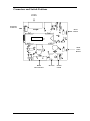
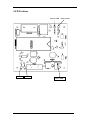
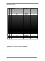
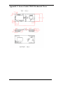
Instant Internet Evaluation Board II-EVB-361MW User Manual Version 1.3 International: Connect One Ltd. 20 Atir Yeda Street Kfar Saba 44643, Israel Tel: +972-9-766-0456 Fax: +972-9-766-0461 E-mail: [email protected] http://www.connectone.com Pub. No. 23-3620-13, Copyright © Connect One, March 2008 Connect One Semiconductors, Inc. 560 S. Winchester Blvd. Suite 500 San Jose, CA 95128 Tel: (408) 572-5675 Fax: (408) 572-5601 Information provided by Connect One Ltd. is believed to be accurate and reliable. However, Connect One assumes no responsibility for its use, nor any infringement of patents or other rights of third parties, which may result from its use. No license is granted by implication or otherwise under any patent rights of Connect One other than for circuitry embodied in Connect One’s products. Connect One reserves the right to change circuitry at any time without notice. This document is subject to change without notice. The software described in this document is furnished under a license agreement and may be used or copied only in accordance with the terms of such a license agreement. It is forbidden by law to copy the software on any medium except as specifically allowed in the license agreement. No part of this document may be reproduced or transmitted in any form or by any means, electronic or mechanical, including but not limited to photocopying, recording, transmitting via fax and/or modem devices, scanning, and/or information storage and retrieval systems for any purpose without the express written consent of Connect One. iChip, Secure Socket iWiFi, Internet Controller, SerialNET, AT+i, and Connect One are trademarks of Connect One Ltd. Copyright 2008 Connect One Ltd. All rights reserved. II-EVB-361-MW User’s Manual ii TABLE OF CONTENTS Introduction .................................................................................................................... 4 Unpacking ...................................................................................................................... 4 Connections.................................................................................................................... 4 Testing the Secure Socket iWiFi Wireless LAN Connection .................................... 4 Installing the II-EVB-361MW Utility and Evaluation Program .................................... 5 Connectors and Switch Positions ................................................................................... 6 LED Positions ................................................................................................................ 7 Bill of Materials ............................................................................................................. 8 Appendix 1: II-EVB-361MW Schematic ...................................................................... 8 Appendix 2: Secure Socket iWiFi Mechanical Views ................................................. 10 Appendix 3: WiFi Configuration Notes ....................................................................... 11 Introduction .............................................................................................................. 11 iChip Wireless LAN Environment Configuration Parameters ................................ 12 Wireless LAN Configuration Web Site Page .......................................................... 13 Wireless LAN Status Report .................................................................................... 13 iChip Wireless LAN Test Mode .............................................................................. 15 Placement and Range Guidelines............................................................................. 15 Wireless LAN Data Privacy/Security Considerations ............................................. 15 International: Connect One Ltd. 20 Atir Yeda Street Kfar Saba 44643, Israel Tel: +972-9-766-0456 Fax: +972-9-766-0461 E-mail: [email protected] http://www.connectone.com Pub. No. 23-3620-13, Copyright © Connect One, March 2008 Connect One Semiconductors, Inc. 560 S. Winchester Blvd. Suite 500 San Jose, CA 95128 Tel: (408) 572-5675 Fax: (408) 572-5601 Introduction This manual is intended to familiarize prospective customers with Connect One’s Instant Internet Evaluation Board II-EVB-361MW. The II-EVB-361MW is an evaluation platform for the Secure Socket iWiFi™ Internet Controller. Secure Socket iWiFi is a secure serial-to-Wireless LAN device server module that also acts as a bridge to connect serial devices to 802.11b/g wireless LANs. Secure Socket iWiFi fits into a socket form-factor and utilizes Connect One’s iChip CO2128SEC Internet communications coprocessor and the AT+i™ command set, a powerful set of Internet protocol commands developed by Connect One to manage Internet connectivity through a wireless LAN connection. Secure Socket iWiFi enables sending and receiving textual and binary data, MIMEencoded email messages; downloading HTML pages or files from a Web server, or items from within a page; Web serving, as well as managing TCP or UDP socket communications (with or without SSL3) over the Internet. It also includes an FTP client and a Telnet client. Secure Socket iWiFi supports numerous security protocols like SSL3/TLS1, 64/128bit WEP encryption, AES-CCM and TKIP encryption, WPA (including AES) and WPA2. Unpacking Take the II-EVB-361MW out of its box. Included in the box are: The II-EVB- 361MW motherboard including Secure Socket iWiFi (iW-SM2128MW) A serial cable with two DB-9 connectors Antenna Power supply adaptor (110V/220V) Connections 1. Connect one end of the RS232 cable to the serial port on the II-EVB-361MW (J1) and connect the other DB-9 connector to the COM1 or COM2 serial port on your PC, or to the serial port of your embedded device. 2. Connect the II-EVB- 361MW to the power supply. Testing the Secure Socket iWiFi Wireless LAN Connection To test the wireless LAN connection, you need to configure the Secure Socket iWiFi to connect to an Access Point: 1. 2. 3. 4. Make sure the Access Point is connected and configured properly. Invoke the iChip Config Utility on your PC. In the main window of the utility, click the Dumb Terminal icon. In the Dumb Terminal window, enter the AT+i command to verify that the iChip is communicating with your PC. You should receive an I/OK in response. II-EVB-361-MW User’s Manual 4 5. Enter the AT+iRP11 command to obtain a report of all the Access Points available in your area. 6. Enter AT+iWLSI=<ssid>. ssid is the ID of the Access Point you connect to. Note that ssid is a case-sensitive string. 7. If you want to enable WEP encryption, configure the following parameters: AT+iWLWM=<n> where n=0 means no security, n=1 means 64-bit key, and n=2 means 128-bit key AT+iWLKI=<n> where n is the WEP key index (n=1..4) AT+iWLK<n>=<keyString> where n is an index between 1 and 4, and keyString is the WEP key string in the nth position. 8. If you want to enable WPA encryption, configure the following parameter: AT+iWLPP=<passphrase> where passphrase is the pass-phrase to be used in generating the WPA1-PSK encryption key At this stage a connection to the Access Point is established. To test the connection, use the iChip Config Utility to perform any activity that requires network connection such as retrieving a web page, sending an email, or opening a socket. Installing the II-EVB-361MW Utility and Evaluation Program II-EVB-361MW enables you to evaluate the Secure Socket iWiFi without changing anything in your current development environment. Using a simple terminal program on a PC, you can issue AT+i commands to the iChip and get responses. AT+i commands are used to configure parameter values into iChip’s flash memory and activate Internet tasks such as email send, sockets, FTP sessions, configuration, and more. A full description of the AT+i protocol can be found in the AT+i Programmer’s Manual on the Connect One website in the Documentation section at http://www.connectone.com. To help you evaluate the iChip, Connect One supplies the iChip Config Utility. This is a Windows-based GUI program that contains intuitive dialog boxes to fully configure iChip. It doesn’t require any knowledge of AT+i commands. It also contains local firmware upgrade functionality. The iChip Config Utility also allows you to perform specific Internet communication tasks such as sending and receiving emails, activating iChip’s websites, entering SerialNET mode, and more. The latest iChip Config Utility version and user manual can be found on the Connect One website at http://www.connectone.com in the Support section. For more information on the iChip Config Utility and its usage, see the iChip Config Utility User’s Manual. II-EVB-361-MW User’s Manual 5 Connectors and Switch Positions ANTENA HOLDER Extension Connector Reset Button II-EVB-361MW Mode Select Button RS232 Host Interface II-EVB-361-MW User’s Manual DC Jack On/Off Switch 6 LED Positions Link/Act LED TXDH Full/Col LED RXDH Power LED II-EVB-361-MW User’s Manual 7 Bill of Materials # Qty Reference Description Manufacturer 1 2 3 4 5 6 7 8 9 10 11 12 13 14 15 16 17 18 19 20 21 22 23 6 4 2 1 1 1 1 1 5 1 4 1 1 1 1 1 1 3 1 2 1 1 1 C1,C2,C8,C9,C11,C13 C3,C4,C5,C6 C7,C10 C12 C14 D1 D2 D3 D4,D5,D7,D8,D9 D6 3.3V,46,47,GND J1 J2 J3 J4 L1 R1 R2,R3,R4 R5 R6,R7 SW1 SW2 SW3 100NF 470NF 1000UF/25V 10UF/16V 1NF/2KVPF LLN4148 1N4001 R.LED G.LED MUR115 TP DB9 FEM DC-JACK-MALE RJ45 HEADER 4x2 68UH/1A 10k 470 0 75 TACK_SW PB SW SWITCH Any Any Any Any Any Any Any Any Any Any Any Any Any Any Any Any Any Any Any Any Any Any Any 24 1 U1 Secure Socket iWiFi Connect One 25 1 U2 SP3238ECA Any 26 1 U3 LM2591HVS-3.3 Any 27 1 U4 SP708TCN Any Appendix 1: II-EVB-361MW Schematic II-EVB-361-MW User’s Manual 8 7 VIN VIN U3 -CDH 1 5 28 1 25 C11 100NF C1+ U2 C1C2+ C2TIN1 TIN2 TIN3 TIN4 TIN5 + VDD 1000UF/25V C10 15 8 9 11 5 6 7 10 12 4 27 C2 100NF V+ V- INVALID RIN1 RIN2 RIN3 TOUT1 TOUT2 TOUT3 TOUT4 TOUT5 GND VDD ROUTB1 ROUT1 ROUT2 ROUT3 FORCEON 4 GND 3.3V TP GND 1NF/2KVPF C14 CHASSIS SW2 PB SW GND GND R6 R7 MSEL 75 75 -CDH232 3 GND R5 0 GND -RES 1 2 4 5 6 7 24 25 26 27 28 29 30 31 32 HOLE3 HOLE4 U1 N.C N.C TX+ TXRX+ RX- J3 1 2 3 4 5 6 7 8 SHILD SHILD RJ45 1 6 2 7 3 8 4 9 5 2 J1 Socket iWIFI RES N.C GND MSEL N.C N.C N.C N.C N.C GND -DTRH232 TXDH232 -CTSH232 RXDH232 -RTSH232 GND GND Connect-ONE C onnect-ONE Ltd. N.C GND N.C VDD Speed N.C Link/Act/RF N.C Full/Col GND N.C CDH RTSH DTRH VDD RXDH TXDH CTSH D9 G.LED 64 63 62 61 60 59 58 57 56 41 40 39 38 37 36 35 34 33 VDD VDD -CDH -RTSH -DTRH RXDH TXDH -CTSH VDD D8 G.LED Sheet 2 1 GND 1 C13 100NF R2 470 D3 R.LED C3 470NF C5 470NF TXDH232 -DTRH232 -RTSH232 -CDH232 RXDH232 -CTSH232 47 Title 2 VDD MSEL RESET D6 MUR115 C4 470NF 3 24 23 22 19 17 16 21 20 18 13 46 TP Document Number 254 IIEVB_361MW IIEVB_361M Size B 2 1 6 2 4 6 8 4 2 2 L1 68UH/1A 1 C6 470NF TXDH -DTRH -RTSH -CDH RXDH -CTSH FORCEOFF TP GND Monday, June 18, 2007 2 Date: 1 J4 1 3 5 7 HEADER 4x2 GND OTPUT FEEDBACK R4 470 VDD 14 GND 3 1 of VDD GND 1 Rev 1.0 VDD C12 10UF/16V D7 G.LED 1 + 8 SW3 2 C8 100NF LM2591HVS-3.3 VDD D4 G.LED R3 470 VDD PGND D5 G.LED SGND 3 1 + GND -RES SP3238ECA 4 DB9 FEM D D2 1N4001 1 C7 VDD 1000UF/25V GND TP C9 100NF U4 MR PFI 6 8 7 5 GND 1 2 1 2 SWITCH GND 1 4 NC RESET RESET PFO 5 RS232 TO HOST ON/OFF 6 2 1 J2 DC-JACK-MALE GND VDD 10k R1 RESET GND SP708TCN 2 1 1 2 5 6 11 10 26 VCC C LLN4148 C1 100NF GND 7 1 D1 SW1 GND 8 1 GND 2 2 VCC 1 GND 3 B A TACK_SW D C B A Appendix 2: Secure Socket iWiFi Mechanical Views II-EVB-361-MW User’s Manual 10 Appendix 3: WiFi Configuration Notes Introduction Wireless LAN stations operate in one of two modes: Infrastructure or Ad-Hoc. In Infrastructure mode, wireless LAN stations connect to a wireless LAN Access Point (AP), which acts as a hub. Wireless LAN stations may connect to each other through the AP. If the AP is connected to LAN, it allows wireless LAN stations to connect to other stations on the LAN. When a gateway is in place, it enables wireless LAN stations to connect to systems across the gateway, as well. In Ad-Hoc mode, two or more wireless LAN stations communicate directly with each other. The Secure Socket iWiFi supports the 802.11b/g wireless LAN communication platform. It uses the iChip™ CO2128 communication controller chip and Marvell 88W8686 WiFi chipset. It incorporates several dedicated AT+i configuration parameters to support the wireless LAN environment. See the table below for a detailed list of WiFi configuration parameters. AT+i Parameter Name WLCH WLSI WLWM WLKI WLKn WLPS WLPP WLRS Description Wireless LAN Communication Channel Wireless LAN System-Set ID Wireless LAN WEP Mode Wireless LAN Transmission WEP Key Index Wireless LAN WEP Key Array Wireless LAN Power Save Personal Shared Key Pass Phrase Wireless LAN Rescan Interval Table 1: AT+i Wireless LAN Configuration Parameters The Secure Socket iWiFi may also be configured to exploit WEP security. iChip supports configuration of both 64-bit or 128-bit WEP keys. In Infrastructure mode, Power Save mode is supported. When activated, Power Save shuts down the station for a limited period of time, during which the Access Point buffers incoming packets destined for the deactivated WiFi station. The station periodically wakes up to retrieve all the buffered packets stored in the Access Point. In this mode, total power consumption is lowered at the expense of higher response latency. The Secure Socket iWiFi may be configured to put the WiFi chipset in Power Save mode in conjunction with iChip’s inherent Power Save mode. II-EVB-361-MW User’s Manual 11 iChip Wireless LAN Environment Configuration Parameters WLCH (Factory Default: 0) In Infrastructure mode, the WLCH parameter must be set to 0. Other available values (1..13) designate the preferred communication channel while in Ad-Hoc mode. WLSI (Factory Default: Empty) This parameter must be assigned with the System-Set-ID string (SSID), which is identical to that configured in the Access Point(s) through which the WiFi station needs to connect. An exception to this is the “Any SSID” configuration, which is configured by simply leaving this parameter empty (or setting to NULL string with AT+iWLSI=””). In the “Any SSID” configuration, the WiFi station will connect to any available Access Point. If more than one Access Point is active, it will choose the one with the stronger radio signal. WLWM (Factory Default: 0) Configure this parameter to designate WEP security usage mode. If WEP is disabled, the WLKI and WLKn parameter settings are irrelevant. Note that WEP settings (with the exception of WLKI) must be identical to those configured in the Access Point device. Possible settings are: WLWM Setting 0 1 2 WEP Security Disabled Enabled, using 64 bit keys Enabled, using 128 bit keys Table 2: WEP Security Mode Settings WLKI (Factory Default: 1) If WEP is enabled, this parameter defines the key index of the WEP key to be used when encoding outgoing WiFi packets. Since WEP includes configuration for an array of four possible keys, WLKI can receive a value in the range [1..4]. The value of this parameter need not be the same as that configured in the Access Point. WLKn (Factory Default: All Empty) These are four consecutive parameters (with n ranging from 1 to 4). The parameters define an array of 4 WEP security keys, which are used to encode outgoing WiFi packets (using the key defined by WLKI) and decode incoming packets according to the key issued by the Access Point device. Key size is 64- or 128-bits, according to the WLWM setting. The parameter values are used only if WEP security is enabled (WLWM > 0). The key values must be identical to those configured in the Access Point device. WLPS (Factory Default: 0) This parameter defines the chipset Power Save mode. When configured for Power Save mode, iChip links its own internal Power-Save mode with that of the Marvell chipset. When iChip’s Power Save mode is activated (AT+iPSE=1), and when WLPS is greater than 0, iChip will force the chipset into Power Save mode. The value stored in WLPS defines the maximum length of time (in milliseconds) during which the Marvell chipset will snooze, before waking up to download any available packets that may have been buffered for it in the Access Point. WLPS may be set in the range: II-EVB-361-MW User’s Manual 12 [0..3600]. When WLPS is set to 0, the Marvell chipset Power Save is disabled, even if iChip enters Power Save mode. WLPP (Factory Default: Empty) This parameter sets the wireless LAN WPA1-PSK pass-phrase to be used in generating the WPA1-PSK encryption key. When empty, WPA security is disabled. If WLSI (SSID) is not empty, WPA1-PSK security is enabled for WiFi connections and WLPP is used in generating the WPA1-PSK encryption key. The allowed value for WLPP is an ASCII string containing 8-63 characters. WLRS (Factory Default: 0) This parameter sets the interval between consecutive scans that iChip performs in search for nearby ad-hoc networks. Scan duration is two beacon periods (200 ms). WLRS may be set in the range: 0-65535 milliseconds. Wireless LAN Configuration Web Site Page iChip’s configuration website includes two views that support configuration and status retrieval of related Wireless LAN parameters. The configuration view displays the configurable Wireless LAN AT+i parameters (WLCH, WLSI, WLWM, and WLKI). New values may be defined and submitted to iChip from the browser. Figure 1: Wireless LAN Web Configuration Wireless LAN Status Report The Wireless LAN AT+i Report (AT+iRP10) returns pertinent status information regarding the active 802.11b/g Wireless LAN link. In response to issuing the report command, iChip will reply with the following syntax: I/(<port stat>, <xfer rate>, <sig level>, <lnk qual>) Where, port stat -- xfer rate -- II-EVB-361-MW User’s Manual Port Status: 0: Wireless LAN adapter not present 1: Wireless LAN adapter Disabled 2: Searching for initial connection 4: Connected 5: Out of range Transfer Rate, in the range 1..4 (1 =>1 Mbps; 2 =>2 Mbps; 3 =>5.5 Mbps; 4 =>11 Mbps) 13 sig lvl lnk qual --- Signal Level [%], in the range 0..100 Link Quality [%], in the range 0..100 The Configuration website contains a live status page with this and some additional status information: Figure 2: Wireless LAN Web Status Display II-EVB-361-MW User’s Manual 14 iChip Wireless LAN Test Mode WLTR This command limits the wireless LAN transmission rate according to the specified command parameter. The table below details the possible parameter values: Maximum Transmission Rate 0 1 2 3 4 Detail Maximum possible transmission rate for the current chipset. 1 Mbps 2 Mbps 5.5 Mbps 11 Mbps Table 3: Maximum Transmission Rate Command Parameter When AT+i WLTR is issued, transmission rate is limited for the duration of the session until another AT+iWLTR command is issued, or iChip is power-cycled. Placement and Range Guidelines 802.11b/g wireless LAN devices connect to wireless LAN Access Points over a maximum range of 300 feet. Actual transmission rate and service quality may vary significantly as a result of environmental obstacles and physical placement of the Access Point and station devices. For best results, refer to the following guidelines: 1. Locate the wireless LAN equipment away from sources of interference, such as PCs, large metal surfaces, microwaves, and cordless phones. 2. Position the wireless LAN access point at an elevated position and as close as possible to the center of the area in which the wireless LAN devices will operate. Wireless LAN Data Privacy/Security Considerations The fact that wireless LAN devices transmit data over a radio link makes them vulnerable to electronic eavesdropping, tampering, and information theft. There are several means by which you may strengthen your wireless LAN access security: Change the factory default SSID setting of the wireless LAN Access Point and station devices. Enable WEP or WPA encryption of the wireless LAN data communications. If you use WEP, it is recommended that you use 128-bit WEP keys. Restrict 802.11b/g wireless LAN access based on MAC address. This is configurable in most Access Point devices. Place the 802.11b/g Wireless Access Point in a location where it cannot be physically tampered with. Store printed SSID and WEP or WPA key settings in a safe place. II-EVB-361-MW User’s Manual 15