1
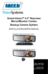
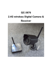
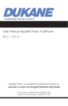
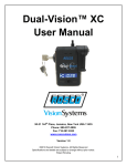
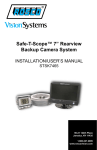
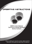
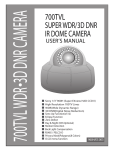
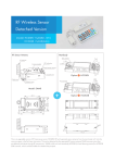
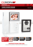
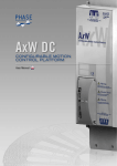
Smart-VisionTM 4.3" Rearview Mirror/Monitor Combo Backup Camera System INSTALLATION/USER'S MANUAL STSK453X Series 90-21 144th Place Jamaica, NY 11435 1.800.227.2095 www.roscovision.com STSK4530 Component List Qty P/N Qty. STSC130W (White) STSC130R (Chrome) STSC130B (Black) *system comes with 1 camera BACK UP CAMERA, INCLUDES: P/N STSC100X HIGH MOUNT, LOOK DOWN CAMERA WITH HARDWARE P/N STSH333 CAMERA POWER & SPLITTER HARNESS 1 STSM230 BACK UP CAMERA MIRROR/MONITOR INCLUDES: P/N STSM1000 4.3" COLOR MIRROR MONITOR P/N STSW1000 WINDSHIELD MOUNT #1 FOR MIRROR MONITOR P/N STSH4530 MONITOR POWER HARNESS 1 STSH330 BACK UP CAMERA EXTENSION HARNESS, 25FT, ROSCO, P/N STSH330 1 with a choice of 3 colors: STSM230 STSM1000 STSC130W STSC130R STSC130B STSC1001 STSC1002 STSC1000 STSW1000 STSH4530 STSH333 STSH330 Notes: • Please read this manual carefully before using the product. • This system is intended as an aid to safe reverse operation. Drivers must always use extreme cautionwhen operating a vehicle. • Specifications subject to change without prior notice. Warning: • To prevent electrical shock, DO NOT OPEN MONITOR CASE. • Avoid exposing monitor to water, rain, moisture etc. • Do not disassemble the camera. This voids the warranty. Disassembling the camera will compromise the waterproof seal. 1 www.roscovision.com STSK4531 Component List Qty P/N Qty. 1 STSC130W (White) STSC130R (Chrome) STSC130B (Black) *system comes with 1 camera BACK UP CAMERA, INCLUDES: P/N STSC100X HIGH MOUNT, LOOK DOWN CAMERA WITH HARDWARE P/N STSH333 CAMERA POWER & SPLITTER HARNESS 1 STSM231 BACK UP CAMERA MIRROR/MONITOR INCLUDES: P/N STSM1001 4.3" CLIP ON COLOR MIRROR MONITOR P/N STSH4530 MONITOR POWER HARNESS 1 STSH330 BACK UP CAMERA EXTENSION HARNESS, 25FT, ROSCO, P/N STSH330 with a choice of 3 colors: STSM231 STSM1001 STSC130W STSC130R STSC130B STSC1001 STSC1002 STSC1000 STSH4530 STSH333 STSH330 Notes: • Please read this manual carefully before using the product. • This system is intended as an aid to safe reverse operation. Drivers must always use extreme cautionwhen operating a vehicle. • Specifications subject to change without prior notice. Warning: • To prevent electrical shock, DO NOT OPEN MONITOR CASE. • Avoid exposing monitor to water, rain, moisture etc. • Do not disassemble the camera. This voids the warranty. Disassembling the camera will compromise the waterproof seal. 2 www.roscovision.com Smart-VisionTM 4.3" Rearview Mirror/Monitor Combo Backup Camera System Rosco Vision Systems introduces a revolutionary new backup camera system for small to medium vehicles. Smart-VisionTM utilizes an interior rearview mirror to display a 4.3" LCD monitor when the vehicle shifts into reverse. This monitor allows the driver to see behind the vehicle for added convenience and safety. The camera has an advanced CMOS lens sensor able to process excellent images under dark and light conditions. The camera has a 170° diagonal field of vision giving superb coverage behind the vehicle and complies with the latest NHTSA 49 CFR Parts 571 and 585 (RIN 2127-AK43), when installed properly. General Technical Specifications: Power Supply: Power Consumption: Current Draw: Video Input: Monitor Dimensions: 12VDC ~3 Watt ~250 mA 1 Vp-p@75 impedance 11"W x 3"H x 1.5"D CONTENTS How To Operate Display............... 4 Color Camera.... 7 Wiring Diagram.......... 5-6 Rearview Mirror Installation........ 8 Camera Installation........ 9 Testing & Maintenance... 10 Installation Tools: 1. 4. 7. 2. 6. 3. 5. 8. 1. Wire Tester 4. Wire Stripper 7. Drill 2. Phillips Screwdriver 5. Pencil 8. Tape 3. Tape Measure 6. Drill Bits 9. Wire Ties (Not Shown) A Century of Automotive Safety 3 How To Operate Display 1. 2. 3. 4. 5. How To Operate Display: Monitor Technical Specifications: 1. V1/V2 - Not Applicable. Screen: 4.3" TFT Color LCD Brightness: 350cd/m2 Contrast ratio: 300:1 Resolution: 480 x 272 Current Draw: Max 120mA Video format: NTSC/PAL Display format: 4 : 3 or 16 : 9 Nomenclature: 12V Working Temp. °F(°C): -5° to 158° (-20° to 70°) 2. "Up" - Menu selection control. 3. Menu - Switches to setup menu. 4. "Down" - Menu selection control. 5. Power - Switches monitor off. Typically not used How To Set Your Monitor: On-screen menu commands may be selected pressing the MENU button while the mirror/monitor is on: Brightness Contrast Saturation Hue Sharpness 4:3/16:9 Reset 4 IMPORTANT: The Rearview Mirror/ Monitor is not intended to be used for prolonged periods of time. Therefore the monitor stays off until triggered by reverse circuit. www.roscovision.com Wiring Diagram Wiring Diagram Option #1: Power Provided From Back of Vehicle (Most Common) 7" Option #2: Power Provided From Front of Vehicle 7" P/N: STSM100X PN: STSH4530 68" 7" AV1 (DO NOT USE) AV2 7" P/N: STSH330 Red Power Wire 10" Trigger (Green) 12" 10" AV2 2" 7" P/N: STSH330 2" Red Power Wire 76" To Chassis P/N: STSH331 Ground Note: Additional wire or adjustment to harness may be required. 3' 10" Trigger (Green) 10" AV2 2" 7" (Red) 11" Chassis Ground Tie all 3 together P/N: STSC100X (Red) 12V (Red) 11" Chassis Ground P/N: STSH332 26' 2" 8" 2" To reverse light circuit at front fuse box. 2" DO NOT USE 76" To Chassis P/N: STSH331 Ground Note: Adjustment to harness may be required. 3' (Red) Trigger (Green) P/N: STSC100X 3' To Chassis 76" Ground P/N: STSH331 12" 3A 250V 11" P/N: STSH330 8" 12" 3A 250V 11" AV1 (DO NOT USE) To Positive Reverse Light Wire At The Rear Of The Vehicle. P/N: STSH332 26' 8" (Red) 7" AV1 (DO NOT USE) Tie both together P/N: STSH332 26' P/N: STSM100X PN: STSH4530 68" To Positive Reverse Light Wire At The Rear Of The Vehicle. 5 7" P/N: STSM100X PN: STSH4530 68" 7" Option #3: Power Provided From Front and Back of Vehicle (Least Common) 12V (Red) 3A 250V 11" 11" Chassis Ground To reverse light circuit at front fuse box. P/N: STSC100X 6 Color Camera *STSC130 Color Camera is also available in chrome (Not Shown) Camera Technical Specifications: Features and Benefits: Signal System: Sync System: Horizontal Resolution: Minimum Illumination: Diagonal Angle: Video Output: Waterproof Grade: Current Draw: Nominal Voltage: Working Temp. °F(°C): • Superb Night Vision NTSC Internal 420TVL 0.2Lux 170° RCA, 1.0Vp-p, 75ohm IP67 Max. 90mA DC12V -22° to 158° (-30° to 70°) • 170° Diagonal field of vision • Easy installation A Century of Automotive Safety 7 Rearview Mirror Installation For standard mirror monitor 1. Attach windshield mounting bracket to the back of STSM230 mirror/ monitor. Be certain that the monitor is in the upright position when attaching the mounting bracket. (Figure 1) 2. Remove old rearview mirror from factory mirror-mount tab. 3. Mount rearview mirror/monitor securely to mounting tab by tightening screw. (Figure 2) Figure. 1 4. Route the 8-pin connector end of the power harness to the location of mirror/monitor (preferably through the headliner and the vehicles A orB pillars). 5. Connect the power harness with the mating 8-pin receptacle end coming out of the mirror/monitor. IMPORTANT: Please be certain to match both guiding lines on each connector for a proper connection. Tightning Screw Figure. 2 For clip on mirror monitor 1. Expand STSM231 mirror monitor clamps and place over existing rear view mirror 8 www.roscovision.com Camera Installation 1. Select a high and centered location at the rear of the vehicle to mount the STSC130 camera. IMPORTANT: When selecting this location it is highly recommended that the image transmitted by the camera show the rear bumper and area behind the vehicle. 2. We do not recommend mounting the camera near the lower area of the vehicle (ex. bumper). This reduces the view of the camera and increases the chance of physical damage to the camera. 3. Once the location for the camera is chosen, drill the mounting hole to the inside of the vehicle using a 5/16 drill bit. Be sure to clear any obstacles before drilling hole. 4. Attach the provided 3M double sided tape to the back of the camera. 5. Insert camera wire through newly drilled hole and mount securely in place. Camera mount in suggested location Mount camera assembly high. (Centered) Figure. 1 Position of camera Figure. 2 Obstructions behind truck 6. To finalize the camera installation, hand tighten the provided 5/16 nut to the back of the camera on the inside of the vehicle. Diamond Plate Typical monitor image of view from properly installed camera Figure. 3 A Century of Automotive Safety 9 Testing How to Test: 1. Apply the parking brakes. 2. Turn Ignition on. (DO NOT TURN ON VEHICLE) 3. Shift into reverse gear. 4. Image should appear on the monitor. Trouble Shooting: Problem No power to monitor while reversing. Solution Check power and reverse trigger connections. 1. Press AV1/AV2 button to change video inputs. "No Signal" appears while reversing. 2. Check video input connections. 3. Check camera power connections. Video image is not sharp. Check camera lens for debris. Maintenance: Always keep camera clear from dirt, snow, and mud. Clean camera with a soft moist cloth. 10 A Century of Automotive Safety 90-21 144th Place Jamaica, NY 11435 www.roscovision.com Ph. 1.800.227.2095 A Century of Automotive Safety Fx. 1.718.297.0323 Printed in China Lit. P/N: 04242012