1
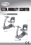
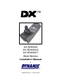
DX-REMG90
DX-REMG90A
DX-REMG90T
Master Remotes
Installation Manual
by
GBK64048 Issue 1, January 2005
About this Manual
This manual has been designed to help you install and configure a Dynamic DX-REMG90
powerchair control unit for a ‘generic’ brand powerchair. For this reason there are no guidelines
for specific applications.
This manual should be read in conjunction with all other relevant DX-System manuals.
If there is a specific requirement for your application, please contact Dynamic Controls or one of
the sales and service agents, to assist you.
Throughout this manual there are a few symbols that will help you quickly identify the purpose of
the paragraph that follows:
Notes & Precautions:
Notes provide supporting information for the previous paragraph
or section that should be followed in order to install, configure,
and use the product safely and efficiently.
Warnings:
Warnings provide important information for the previous
paragraph or section that must be followed in order to install,
configure, and use the product safely and efficiently.
The term ‘programming’ used throughout this manual refers to adjusting parameters and
configuring options to suit an application. ‘Programming’ does not change or alter any software
within the controller and is performed using a controlled programming tool available only to
authorised personnel.
The term ‘accessory’ used throughout this manual refers to equipment that is ancillary to the
main functioning of the control system. It does not refer to an accessory of the wheelchair. The
control system is a component of the wheelchair.
DX is not user serviceable. Specialized tools are necessary for the repair of any component.
Do not install, maintain or operate this equipment without reading, understanding and following
this manual – including the Safety and Misuse Warnings – otherwise injury or damage may result.
Due to continuous product improvement Dynamic reserves the right to update this manual.
This manual supersedes all previous issues, which must no longer be used.
Dynamic reserves the right to change the product without notification.
Any attempt to gain access to or in any way abuse the electronic components and associated
assemblies that make up the powerchair system renders the manufacturer’s warranty void
and the manufacturer free from liability.
Dynamic and the Dynamic logo are trademarks of Dynamic Controls.
All other brand and product names, fonts, and company names and logos are trademarks or
registered trademarks of their respective companies.
Dynamic owns and will retain all trademark rights and Dynamic or its licensors own and will
retain all copyright, trade secret and other proprietary rights, in and to the documentation.
All materials contained within this manual, in hard-copy or electronic format, are protected by
copyright laws and other intellectual property laws.
© Copyright 2005 Dynamic Controls. All rights reserved
Contents
1
Introducing DX ........................................................ 1
2
Introducing the G90 ................................................ 3
3
G90 Operation ......................................................... 5
3.1
3.2
3.3
3.4
3.5
3.6
3.7
3.8
3.9
4
Installation and Testing ........................................ 21
4.1
4.2
4.3
5
Mounting................................................................................... 21
G90 Connection with the DX System ....................................... 23
Testing...................................................................................... 24
Programming G90 ................................................. 27
5.1
5.2
5.3
5.4
5.5
6
The Display Area........................................................................ 5
The G90 Keypad ........................................................................ 7
The G90A Keypad and Jack Sockets....................................... 10
The G90T Keypad and Toggle Switches .................................. 13
ECU Mode................................................................................ 16
Lighting Menu Mode ................................................................. 17
Lock Mode................................................................................ 17
The Joystick ............................................................................. 18
Charging................................................................................... 19
Introduction............................................................................... 27
Auto Download ......................................................................... 28
Programming with Wizard ........................................................ 29
Optimising Chair Stability & Controllability................................ 33
Programmable Joystick Throw/Shape ...................................... 35
Diagnostics............................................................ 37
6.1
6.2
6.3
6.4
6.5
Introduction............................................................................... 37
Diagnostics Tools ..................................................................... 37
Flash Codes ............................................................................. 38
Limp Mode................................................................................ 41
Battery Gauge .......................................................................... 41
7
Specifications........................................................ 43
8
Appendices............................................................ 45
8.1
8.2
8.3
8.4
8.5
8.6
8.7
8.8
8.9
Programmable Parameters (details)......................................... 45
Menu Maps............................................................................... 50
Programming Accessories........................................................ 52
Intended Use and Regulatory Statement.................................. 53
Maintenance............................................................................. 54
Warranty................................................................................... 54
Safety and Misuse Warnings.................................................... 55
Electromagnetic Compatibility (EMC) ....................................... 57
Contact Details ......................................................................... 58
Table of Contents
3
1
Introducing DX
DX is a modular, expandable power wheelchair control system. This
modularity allows the system to be expanded and customized to particular
end-user needs and handles the requirements from basic driving to full
environmental control. A power module and remote are required along with a
DXBUS cable to form the base of any DX system. A variety of modules are
available to access additional functions and features.
Example DX System
Chapter 1: Introducing DX
1
THIS PAGE IS LEFT BLANK INTENTIONALLY
2
GBK64048: Issue 1 – 17/01/2005
2
Introducing the G90
The G90 range are DX master remotes with many new features and
enhancements including:
!
Improved drive performance, including front wheel drive options
!
Larger button size with enhanced tactile feedback
!
A large, super bright display for enhanced visibility in bright sunlight
!
Multi-colour icon based displays for intuitive operation
!
New control methods and increased configurability
!
Improved head control support
!
An Environmental Control Unit (ECU) mode
!
High power horn output
Three G90 variants are available:
DX-REMG90
DX-REMG90A
DX-REMG90T
Featuring jack sockets for
external switches
Featuring toggle switches
for On/Off, Mode Up and
Mode Down
A DX wheelchair control system comprises of two or more
compatible modules. Each module has its own installation
manual.
This manual describes the G90 and its variants only and
therefore must be read in conjunction with the other DX
Modules to be used in your application.
Chapter 2: Introducing the G90
3
THIS PAGE IS LEFT BLANK INTENTIONALLY
4
GBK64048: Issue 1 – 17/01/2005
3
G90 Operation
3.1
The Display Area
All G90 variants contain an identical display area consisting of:
No.
Item
Description
1
Actuator Icons
When illuminated, the remote is in Seat Mode.
The selected actuator is indicated by a flashing
icon. Only enabled actuators are illuminated.
2
ECU Mode Indicator When illuminated, the remote is in ECU Mode.
3
Hazard Light
Indicator
Shows the status of the hazard lights.
When flashing, the hazard lights are on.
4
Left Turn Indicator
Shows the status of the left indicator.
When flashing, the left indicator light is on.
5
Battery Gauge
6 multi-coloured LEDs depict charge state of the
battery. All 6 LEDs on indicate a full charge.
6
7 Segment Display
Displays current Drive Profile, and Lighting
Menu if enabled. Attendant control mode is
shown by ‘A’. Inhibit mode is shown by ‘-‘. Other
symbols are used in ‘Head control’, refer Section
8.2.
7
Right Turn Indicator Shows the status of the right indicator.
When flashing, the right indicator light is on.
8
Headlight Indicator
9
Lock/System Status Red flashing LED indicates the keypad is
LED
locked. Green LED denotes the status of the
system: on steady indicates no system faults,
flashing indicates a fault. Refer Section 6.3.
Shows the status of the headlights.
When illuminated, the headlights are on.
Chapter 3 : G90 Operation
5
Note:
To ensure wiring compatibility with existing DX products such as
the DX-REM34 Dolphin Remote, the following DX-CLAMB
outputs should be used. A programmable option Both Leg
Rests Enable allows extra flexibility by simultaneous operation
of DX- CLAMB channels 3 and 4, refer Section 5.3.
LED Icon
6
Description
DX-CLAMB Output
Left Foot Rest
3
Seat Tilt-In-Space
1
Back Recline
2
Seat Height
5
Right Foot Rest
4
GBK64048: Issue 1 – 17/01/2005
3.2
The G90 Keypad
The G90 variants each have a slightly different keypad, optimised for different
applications. The G90 variant features:
DX-REMG90
10. On/Off Button
To turn the power on press the On/Off button.
The current battery charge will be indicated and the
System Status LED will illuminate and not flash.
Press the On/Off button again to turn the power off.
11. Headlights/Hazard Lights
Headlights
To turn the Headlights on/off, press and release (‘short
press’) the Headlight/Hazard Light button.
Chapter 3 : G90 Operation
7
Hazard Lights
To toggle the Hazard Lights on/off, press and hold (‘long
press’) the Headlight/Hazard Light button.
12. Right Indicator
Press the Right Indicator button to activate the right
indicators.
Press again to turn off.
13. Horn
Pressing the Horn button will sound the horn for as long
as the button is pressed.
14. Left Indicator
Press the Left Indicator button to activate the left
indicators.
Press again to turn off.
15. Mode
Each press of the Mode button will increment the drive
profile, up to the maximum configured value and then
back to profile 1. The current drive profile will be shown
in the 7 Segment Display.
If accessory functions are present, further presses of the
Mode button will select these modes in turn. If
accessories are enabled but not present a ‘0’ will be
displayed.
8
GBK64048: Issue 1 – 17/01/2005
Note:
If the chair is driving and the Mode button is pressed, the drive
profile will increase by a single increment with each press until
the maximum configured value is reached. While driving, Mode
will not enter any available accessory modes.
The programmable parameter Change Profile While Driving
can be used to select if changes to drive profile whist driving are
required.
The programmable parameter Wrap Profiles is not used for this
product variant.
The programmable parameter Allow non-driving Profile
should be used to access accessory options.
Chapter 3 : G90 Operation
9
3.3
The G90A Keypad and Jack Sockets
DX-REMG90A
10. On/Off Button
To turn the power on press the On/Off button.
The current battery charge will be indicated and the
System Status LED will illuminate and not flash.
Press the On/Off button again to turn the power off.
12. Right Indicator
To turn the Right Indicator on/off, press and release
(‘short press’) the Right Indicator button.
To toggle the Hazard Lights on/off, press and hold (‘long
press’) the Right Indicator button.
10
GBK64048: Issue 1 – 17/01/2005
13. Horn
Pressing the Horn button will sound the horn for as long
as the button is pressed.
14. Left Indicator
To turn the Left Indicator on/off, press and release
(‘short press’) the Left Indicator button.
To toggle the Headlights on/off, press and hold (‘long
press’) the Right Indicator button.
15. Mode
Each press of the Mode button will increment the drive
profile, up to the maximum configured value and then
back to profile 1. The current drive profile will be shown
in the 7 Segment Display.
Note:
If the chair is driving and the Mode button is pressed, the drive
profile will increase by a single increment with each press until
the maximum configured value is reached.
The programmable parameter Change Profile While Driving
can be used to select if changes to drive profile whist driving
are required.
The programmable parameter Wrap Profiles is not used for
this product variant.
The Mode button does not enter the accessory modes.
If using the Mode Jack, available accessory modes can be
entered, but only when not driving. This is to help prevent
inadvertent access to accessory options.
Chapter 3 : G90 Operation
11
16. ASK (Accessory Shortcut Key)
If you are in Drive Mode, a press of the ASK button will
navigate you to the last used accessory function, e.g.
actuator control. If you are already in Accessory Mode,
a press of ASK will take you to the next available
accessory mode, e.g. ECU or lighting.
To return to Driving, simply press the Mode button.
This feature significantly reduces the complexity and
number of key presses to access common features.
Note:
If the chair is driving and the ASK button is pressed, the
command is ignored until the chair has stopped.
17. Jack Sockets
Jack Sockets are provided on the G90A for accessing
On/Off and Mode functions via third party switches.
These connections are protected by a screw down cover
and are clearly labelled. When 3rd party switches are
connected, ensure the wiring is routed suitably to exit
from the notches in the cover. Carefully replace the
cover and retighten the screw.
Depending on the dimensions of the 3rd party jack plugs
used, the jack plugs may be orientated in either of two
ways as shown.
Maximum tightening torque for the M3 cover screw is 0.6
Nm.
Warning:
Do not operate any G90 without the
cover installed correctly. The cover is an
essential part of the ingress protection.
12
GBK64048: Issue 1 – 17/01/2005
3.4
The G90T Keypad and Toggle Switches
DX-REMG90T
10. On & Off Button
To turn the power on press the On/Off button.
The current battery charge will be indicated and the
System Status LED will illuminate and not flash.
Press the On/Off button again to turn the power off.
13. Horn
Pressing the Horn button will sound the horn for as long
as the button is pressed.
Chapter 3 : G90 Operation
13
16. ASK (Accessory Shortcut Key)
If you are in Drive Mode, a press of the ASK button will
navigate you to the last used accessory function, e.g.
actuator control. If you are already in Accessory Mode,
a press of ASK will take you to the next available
accessory mode, e.g. ECU or lighting.
To return to Drive mode, simply press any Mode button.
This feature significantly reduces the complexity and
number of key presses to access common features.
Note:
If the chair is driving and the ASK button is pressed, the
command is ignored until the chair has stopped.
14
GBK64048: Issue 1 – 17/01/2005
17. Mode Up
Each press of the Mode Up button will increment the
Drive Profile to its maximum configured value. The
current Drive Profile will be shown in the 7 Segment
Display. For example, if the remote is in Drive Profile 2,
a single press of the Mode button will take you to Drive
Profile 3.
This button does not to enter any available accessory
modes.
18. Mode Down
Each press of the Mode Down button will decrement the
Drive Profile. The current Drive Profile will be shown in
the 7 Segment Display. For example, if the remote is in
Drive Profile 2, a single press of the Mode button will
take you to Drive Profile 1.
This button does not to enter any available accessory
modes.
19. Toggle Switches
Two toggle switches are provided to provide a more
traditional interface for controlling power On/Off, Mode
Up and Mode Down. Operating the right toggle switch,
up or down, toggles the power On/Off. Operating the left
toggle switch upward advances the mode, and
downward will decrease the mode.
Chapter 3 : G90 Operation
15
Note:
The function of the Mode toggle switch functions is subtly
different to the keypad Mode functions.
The Mode toggle switches allow access to available accessory
modes when not driving. For example, if stationary and in Drive
Profile 5, pressing the Mode up toggle will enter available
accessory modes.
The parameter Change Profile While Driving can be used to
select if changes to drive profile whist driving are required.
3.5
ECU Mode
ECU Mode enables the G90 remote to be used with a
DX-ECU Module, to interface to 3rd party devices such
as environmental controls and communication aids.
The joystick (or input device) can be used to control up
to 4 ECU functions by using the forward, reverse, left
and right directions to operate DX-ECU channels 1, 2, 3
& 4. The programmed Joystick Switch Threshold will
determine the joystick deflection required to operate the
ECU function. The Left and Right Indicator buttons can
be used to operate an additional 2 functions, ECU
channels 5 & 8.
The diagonal directions (e.g. forward and left) allow
simultaneous operation of two ECU channels.
ECU mode is completely ‘plug and play’ - no
programming is required. Simply connect the DX-ECU
module, (without the supplied ‘Molex jumper’ cable) and
cycle the power. The G90 supports ‘ECU1’ only.
Refer to DX-ECU installation manual (GBK64227) for
further details.
16
GBK64048: Issue 1 – 17/01/2005
3.6
Lighting Menu Mode
When in Lighting Menu Mode, the 7 Segment
display shows 3 horizontal lines.
Moving the joystick forward will toggle the
Headlights.
Moving the joystick left will toggle the Left turn
Indicators.
Moving the joystick right will toggle the right turn
Indicators.
Moving the joystick backward will toggle the
Hazard Lights.
This menu option can be disabled with the
parameter Lighting Menu Disable.
3.7
Lock Mode
The Key Lock system uses a magnetic key to power the
wheelchair down to prevent subsequent unauthorized
driving. The Key Lock can be disabled with the
parameter Lock Enable.
To Lock the system:
Swipe the magnetic key across the key symbol on the
G90 Remote. The system will beep and automatically
power itself down.
To Unlock the system:
Press the On/Off button to power up the system. The
flashing red key symbol shows the system is locked.
Swipe the magnetic key across the key symbol, the LED
will stop flashing the chair may be driven as normal. If
the wheelchair is not unlocked, G90 will automatically
turn itself off.
Chapter 3 : G90 Operation
17
3.8
The Joystick
Moving the joystick will cause the powerchair to drive
in that direction. The amount of joystick movement will
determine the speed that the powerchair will move in
that direction.
The programmable parameter Short Throw Travel
allows the amount of movement required to drive the
chair in any direction at full speed to be customized.
The programmable parameter Joystick Switch
Threshold determines the amount of joystick
movement to operate accessory modes, such as
actuators.
Joystick Out of Neutral at Power up (OONAPU) occurs
if the joystick is out of neutral when switched on. If this
happens the System Status LED will flash constantly.
Releasing the joystick within a few seconds will cancel
the indication otherwise a ‘latching fault’ will occur. If
the user has difficulties switching the power on without
moving the joystick, use the parameter Disable
OONAPU Faults.
18
GBK64048: Issue 1 – 17/01/2005
3.9
Charging
Plug the battery charger into the charging socket
located at the front of the G90 Remote.
Driving is inhibited while the system is being
charged as denoted by ‘-‘ displayed on the 7
segment display. However, it is possible to use
accessory functions e.g. actuators.
This inhibit signal is provided within the battery
charger plug and is a link from pin 2 to pin 3.
Ensure the battery charger is compatible with this
configuration before connection.
Once the Battery Charger displays a ‘full’ battery
charge, the battery charger plug may be removed.
Warning:
Before connecting the battery charger ensure that it is
compatible with the G90. The configuration of the G90 is:
Pin 1 Battery Positive (B+)
Pin 2 Battery Negative (B-)
Pin 3 Inhibit
The inhibit signal must be provided from pin 2 to pin 3 of the
battery charger plug. Dynamic Controls recommends the use
of suitable Neutrik plugs only.
Chapter 3 : G90 Operation
19
THIS PAGE IS LEFT BLANK INTENTIONALLY
20
GBK64048: Issue 1 – 17/01/2005
4
Installation and Testing
4.1
Mounting
All dimensions are mm
G90 & G90A
G90T
The G90 remotes can be mounted on either side of the wheelchair to
accommodate left-handed or right-handed users.
G90 must be mounted using all four (4), M5 Roll Tap Cap Screws.
The mounting is backwardly compatible with the previous DX-REMG80 range.
Maximum tightening torque of the screws is 2.7Nm.
Warning:
For safe installation, select a screw length that protrudes
between 7mm and 11mm into the case. Do not over-tighten.
Warning:
All G90 variants are not waterproof and must be protected from
water ingress as appropriate.
Chapter 4: Installation and Testing
21
Note:
If the programmer socket needs to be accessible when the DX
Remote is mounted, make allowance for this prior to fitting.
Note:
G90T. Adequate clearance should be provided to allow user
access and reliable operation of the toggle switches.
G90A. Adequate clearance should be provided for the auxiliary
switch wiring. Precautions should be taken to prevent trapping
and damage to the switch wiring.
22
GBK64048: Issue 1 – 17/01/2005
4.2
G90 Connection with the DX System
The G90 has 2 identical DXBUS connectors that enable a
suitable length DXBUS cable to be used to interconnect to
the remainder of the DX system.
DXBUS cables are available in a variety of lengths.
Warning:
If only one DXBUS connector is used on the G90 and the
remaining connector is accessible to the wheelchair user, a
blanking cap, GME64909 should be fitted to the unused
connector. This will comply with the relevant clause of ISO7176
Part 14.
Warning:
Care should be taken if DXBUS cables are disconnected.
Any protruding screws should be either plastic or plastic coated
to prevent short circuits occurring with the DXBUS cable pins.
Chapter 4: Installation and Testing
23
4.3
Testing
Ensure that all DX Modules used in your DX System have been installed as
specified in their respective Installation Manuals. The G90 needs to be
correctly programmed for the appropriate wheelchair application prior to
testing.
The G90 is a DX Master Remote. The Master Remote contains the complete
wheelchair system set up, from which all DX Modules download their relevant
information when the DX System is first turned on.
1.
Raise the wheels off the ground using blocks under the
powerchair frame so that the wheels can turn freely.
2.
Recheck all wiring, paying particular attention to polarities of
batteries, motors and park brakes.
3.
Make the final connection to the Battery Positive (+) terminal and
close the circuit breakers.
4.
Press the On/Off switch to power up the system. The correct
response is a steady System Status LED, at least one of the
battery LEDs will be on, and the Mode display will indicate a
number from 1-5.
Note:
The first time the G90 is turned on, the System Status LED will
flash a fault. This is because the G90 must download its
information to the DX Power Module. Turn the remote off, then
back on to clear this fault.
24
5.
Press the Power button again to turn the system off. Ensure it
turns off correctly. Press it again to turn it on.
6.
Press the Mode button a number of times. Check that the display
changes as expected.
7.
Ensure the horn is functioning correctly by pressing the Horn
button.
8.
Check all other switches operate correctly.
9.
Check the Key Lock system operates correctly.
10.
Turn each drive wheel by hand to check that the park brakes are
engaged. The wheels should not move.
11.
Push the joystick slightly out of neutral and listen for the “click” as
the park brakes disengage.
GBK64048: Issue 1 – 17/01/2005
12.
Move the joystick in all directions and ensure that the wheels
respond smoothly and in the correct direction.
13.
Release the joystick to neutral and listen for the click of the park
brakes re-engaging.
14.
Turn off the system and remove the blocks from under the
powerchair.
15.
Turn G90 back on and ensure the mode is in a slow drive profile.
16.
Sit in the powerchair and drive in all directions slowly, checking for
precise and smooth control.
17.
Repeat at higher speeds.
18.
Drive the wheelchair on a 1:6 ramp and check for normal power,
smoothness and parking.
19.
Perform the remainder of the tests as outlined in the Testing
sections of the Installation Manuals of all other DX Modules used
on the wheelchair.
20.
Repeat testing as required until chair performance is as expected.
Chapter 4: Installation and Testing
25
THIS PAGE IS LEFT BLANK INTENTIONALLY
26
GBK64048: Issue 1 – 17/01/2005
5
Programming G90
Warning:
Performance adjustments should only be made by
professionals in the health care field or by persons fully
conversant with the adjustment process and the user’s
capabilities.
Incorrect settings, or programming in an unsafe location, could
cause injury to the operator or bystanders, or damage to the
vehicle or surrounding property.
After the vehicle has been configured, check to make sure the
vehicle performs to the specifications entered in the
programming procedure. If the vehicle does not perform to
specifications, reprogram it. Repeat this procedure until the
vehicle performs to specifications. If the intended operation
cannot be achieved, contact your service agent.
Ensure that deceleration parameters are always higher than
acceleration parameters for a safe response.
It is the health care professionals responsibility to ensure that
the user is capable both of cognitively understanding and
physically operating the programmed features and functions.
With inappropriate programming settings, certain features and
options may not be accessible or perform as expected.
5.1
Introduction
DX is a fully programmable system, which can be optimized for particular
chair types and to suit the driving environment and preferences of individual
users.
The driving performance of the DX System is dependent on its programming
with the DX Remote and Power Module being the modules most responsible
for defining the driving performance of the DX System.
DX can be programmed at 3 points:
During manufacturer by Dynamic – Default Programs
Prior to shipping, each module is loaded with sensible default
settings.
By the Wheelchair Manufacturer (OEM)
OEMs use the PC based “Wizard” programming tool to develop
programs optimized for particular wheelchair models. Each
program defines the technical attributes necessary to match the
Chapter 5: Programming G90
27
controller to the chair (current limits etc), as well as a drive
performance that suits the typical user. The resulting programs
may be copied into each DX System as part of the chair
production process.
The G90 range of controllers are programmable via Wizard
version 5.02 and later.
In the field by the Dealer or Therapist
A Hand Held Programmer (HHP) is used to tune the typical driving
performance to a drive performance optimized for the individual
chair user, including selection of the input device.
Chair Speed is a new feature that can simplify the dealer
customisation of a chair with a single setting.
Existing G80 Wizard programs can be converted into G90 compatible
programs. Please contact your local Dynamic Representative for details.
5.2
Auto Download
The DX System has a feature called Auto Download. It is designed to
minimize programming requirements associated with Module servicing by
down loading the correct programming to a replacement DX Module.
If a DX Module is replaced, it is likely that the replacement module is
programmed differently from the one that it replaces. This could leave the
wheelchair in a dangerous condition. DX automatically detects that a DX
Module swap has occurred and the programmed data from the old module is
transferred to the replacement module. The Auto Download occurs
immediately on power up after the Module has been replaced. This applies to
all DX Modules except the DX Remote.
Warning:
When the G90 is replaced, it will perform an Auto Download to
all DX Modules. This may result in incorrect and dangerous
programming for a particular wheelchair system.
Program the suitable settings in the Remote by using the
Wizard before you attempt to drive or test the DX System.
28
GBK64048: Issue 1 – 17/01/2005
5.3
Programming with Wizard
Wheelchair manufacturers use Wizard to create standard wheelchair
programs for different chairs. Wizard is an advanced and sophisticated tool
and all parameter options are described within it. For a complete list of
parameters and settings, refer to Wizard. The new parameters for DX and
G90 are described here.
Wizard Section: REMG90 Specific Options
Parameter
Name
Description
Remote Type
Number
This is not an adjustable parameter. This is used by Dynamic
during the manufacturing process.
Joystick Only
Operation
If enabled, this allows the functions of the wheelchair to be
controlled using only a four quadrant input device, such as a DXRJM. This helps prevent the user having to pressing any buttons.
Escape Timeout should be used in conjunction with this feature
and should be set to an appropriate value. Refer to section 8.2 for
detail of operation.
3 Quadrant
Mode
If enabled, this allows the functions of the wheelchair to be
controlled using a 3 quadrant input device (RIM style) such as a
DX-RJM as a head-control. Joystick Only operation must also
be enabled. Escape Timeout should be used in conjunction with
this feature and should be set to an appropriate value. Refer to
section 8.2 for detail of operation.
Lighting Menu
Disable
If set to YES, the lighting menu option on the 7 Segment is
removed. Keypad lighting buttons, if fitted always operate lighting.
This option should be set to NO for user who are unable to press
the lighting buttons.
Both Leg Rests
Enable
If enabled, a 6th actuator option is provided in the menu. This
allows the simultaneous operation of actuator channels 3 & 4.
Both channels must also be enabled. This option is depicted by
the two actuator icons flashing on the display. This feature is not
compatible with the DX-TAM.
Escape Timeout Sets the escape timeout period for joystick only operation in
multiples of 0.1 seconds. E.G. 10 gives a 1 second timeout
period. Set to zero to disable. It is recommended that Escape
Timeout is used for all Joystick Only Operation applications.
Settings of between 10 and 30 are likely.
Reverse Escape Allows a reverse joystick command to escape from drive mode.
Enable
This is an optional escape method for Joystick Only Operation.
Axis Swap in
Actuator Mode
If set to YES, the forward/reverse inputs will select actuators,
left/right will operate. If set to NO the forward/reverse inputs will
operate actuators, left/right will select. Useful for 4-quadrant
head control etc. Has no effect in 3 quadrant head control as
left/right always operate.
Chapter 5: Programming G90
29
Parameter
Name
Latched
Actuators
LED Test
Enable
Description
If enabled, all actuator channels are latched, i.e. move joystick
and actuator movement starts and move again to stop.
Pressing the mode or power button will also stop the actuator
movement at any time.
If enables a test pattern to be shown on the display area every
time the G90 is powered up. Set to no to prevent this display.
Warning: Latched Actuators
When Latched Actuators are enabled, actuators will continue
to move after the user releases the input device. This option
should only be used by the OEM for users capable of
understanding the function and cancelling the operation of the
latched actuators safely. The OEM should also use an
appropriate value for the parameter Actuator Timeout to set
the maximum duration of the actuators.
Wizard Various Sections: Chair Speed Options
These are the associated parameters that can provide dramatically simplified
dealer customisation of the powerchair.
Parameter
Name
30
Description
Chair Speed
Enable
Enables the parameter Chair Speed and allows the HHP to be
used to easily adjust it. Refer to parameter Chair Speed.
The OEM enables this parameter if simplified dealer
programming is required.
Chair Speed
If Chair Speed is enabled, this adjusts the overall speed of the
chair easily with the HHP. Setting of 10 allows ‘Maximum’ speed
settings, 0 uses ‘Minimum’ speed settings. This is displayed on
the HHP by the ‘#’ symbols.
Forward Speed
@ Minimum
Defines the maximum speeds when the joystick is fully deflected
in the stated direction while G90 is in the selected Drive Profile
(1-5). Used if the Chair Speed adjustment is enabled or the
speed pot (if fitted) is down.
Reverse Speed
@ Minimum
Defines the maximum speeds when the joystick is fully deflected
in the stated direction while G90 is in the selected Drive Profile
(1-5). Used if the Chair Speed adjustment is enabled or the
speed pot (if fitted) is down.
Turning Speed
@ Minimum
Defines the maximum speeds when the joystick is fully deflected
in the stated direction while G90 is in the selected Drive Profile
(1-5). Used if the Chair Speed adjustment is enabled or the
speed pot (if fitted) is down.
GBK64048: Issue 1 – 17/01/2005
Selecting Chair Speed Enable will change the screen display on the HHP.
When the HHP is plugged in, the initial screen will appear as below.
Chapter 5: Programming G90
31
Wizard Section: Remote Control Settings
These parameters provide a new level of user customisation options and are
very powerful for special adaptations.
Specific applications include 3rd party switch control of Mode up, Mode down,
Horn and lighting functions.
Parameter
Name
Description
ARC always
drives
Actuators
This provides an option for what the actuator 1 and 2 switches of
the DX-ARC5 or DX-ARC-SWB switchbox are used for.
Yes means they always control actuators 1 and 2.
No allows them to be a switch joystick.
To allow driving, also set the Joystick Source to ARC in the
selected profile.
ARC drives
Actuators 1&2
in Profile 0
Used in conjunction with ARC Always Drives Actuators.
Profile 0 is the accessory profile.
Yes allows the DX-ARC5 or DX-ARC-SWB to control actuator 1
and 2 in accessory mode but allows the same buttons to control
driving in other profiles.
No allows them to be used for driving only.
To allow driving also set the Joystick Source to ARC in the
selected profile.
ARC drives
Actuator 3
This provides an option for what the actuator 3 switches of the
DX-ARC5 or DX-ARC-SWB switchbox are used for.
Yes enables control of actuator 3.
No enables these switches to control the left and right indicators.
Press both switches to operate hazard lights.
ARC drives
Actuator 4
This provides an option for what the actuator 4 switches of the
DX-ARC5 or DX-ARC-SWB switchbox are used for.
Yes allows control of actuator 4.
No allows these switches to control the horn and headlights.
ARC drives
Actuator 5
This provides an option for what the actuator 5 switches of the
DX-ARC5 or DX-ARC-SWB switchbox are used for.
Yes allows control of actuator 5.
No allows these switches to control Mode up and Mode down.
These mode controls do not allow access to accessory menus on
the DX-REMG90A or T. but it does a on the REMG90. This
ensures there is always a flexible solution.
Refer to DX-ARC-SWB installation manual (GBK62297) for further details.
32
GBK64048: Issue 1 – 17/01/2005
5.4
Optimising Chair Stability & Controllability
The G90 features an advanced set of parameters to provide improved
powerchair stability and are particularly useful for FWD/MWD applications.
Wizard Section: Drive Profiles
Parameter
Name
Description
Grip
Defines the level of assistance G90 will provide in an effort to
improve chair stability. Grip of 100% means no assist is given,
while 0% means maximum assistance is given to user requests.
Speed X Turn
for Grip
The absolute maximum speed/turn product for which the chair is
unconditionally stable. G90 will assist a user to ensure this value
is not exceeded, to a degree dependant on the Grip programmed
for the response in use. The optimum value of Speed X Turn for
Grip is determined experimentally for each chair design.
Accel out of a
Turn for Grip
A temporary modifier of Speed X Turn for Grip when a user
requests fast acceleration forward while the chair is turning. A
value of 0 does not affect Speed X Turn for Grip at all, up to a
value of 100%, which causes a progressive temporary reduction
in Speed X Turn for Grip under these acceleration conditions.
Accel into a
Turn for Grip
A temporary modifier of Speed X Turn for Grip when a user
requests fast sideways acceleration while the chair is moving
forward. A value of 0 does not effect Speed X Turn for Grip at
all, up to a value of 100% which causes a progressive temporary
reduction in Speed X Turn for Grip under these acceleration
conditions.
Turning @ Full
Speed
A modifier of Turning Speed @ Maximum when the joystick is
pushed full forward. A value of 100% has no effect, a value of
50% will reduce steering (at full speed) by a factor of 50%.
Turning Accel
@ full Speed
Used in conjunction with Turning @ Full Speed to achieve a less
sensitive but more responsive turn characteristic at high speed.
These options are set by the wheelchair manufacturer to obtain optimal drive
performance, safety and control for each particular chair design. They are
best derived from experimental adjustment as individual chair geometry has a
significant effect.
Grip should not be utilised by the OEM to control the stability of the
wheelchair as it is a Dealer accessible parameter.
Chapter 5: Programming G90
33
Preventing Front Wheel Drive Chairs From Spinning
The 3 options for Speed X Turn for Grip, Accel out of a Turn for Grip and
Accel into a Turn for Grip are a set of parameters that define a Virtual
Restrictor Plate (VRP) specifically designed to improve the safety and
controllability of Front and Mid-Wheel Drive chairs.
These 3 “Speed X Turn” parameters together define the mechanical
properties that affect the stability of the chair and are set by the manufacturer
for each particular chair design.
They are NOT designed to be tuned for specific users.
Chair stability is defined by the ability of the chair to make a turn at speed
without losing control. A chair may be stable turning slightly while moving at a
high speed forward, or it may be stable making a fast turn on the spot, but it
may be unstable making a sharp turn at a high speed. For any chair design,
there is a maximum combined value of Speed and Turn for which the chair will
not lose control. Loss of control means the chair’s inertia and turn component
are such that the tyres skid, rendering any action from the controller
ineffective. The chair design, the state and inflation of the tyres, the friction of
the driving surface, and the position of the user affect skidding.
Possible starting point for FWD wheelchairs could include:
Parameter Name
Potential Setting
Speed X Turn for Grip
65%
Accel out of a Turn for Grip
150%
Accel into a Turn for Grip
150%
Turning @ Full Speed
70%
Turning Accel @ full Speed
200%
Note:
These settings are to be used as a guide only. It is the
responsibility of the wheelchair manufacturer to ensure the
program is safe and suitable for their particular chair
configuration.
34
GBK64048: Issue 1 – 17/01/2005
5.5
Programmable Joystick Throw/Shape
The G90 features a Programmable Joystick Throw and Shape. These
options can be set by the dealer or therapist to reduce the amount of joystick
movement required to suit the physical abilities of specific users.
Reducing the Pressure or Movement to Operate a Joystick
The Short Throw Travel and Short Throw Shape parameters are used
together to create custom VRPs on a user by user basis. These are solely for
making the joystick more sensitive.
As supplied, the G90 will reach full speed only when the joystick is pushed as
far as it can mechanically go (i.e. when it hits the restrictor plate).
For some users, it may be difficult if not impossible to provide either the force
or deflection to move the joystick this far, in one or more directions. In these
cases it may be useful to use the Short Throw Travel parameter to reduce
the amount of deflection (and therefore pressure) required.
However, as the Short Throw Travel is reduced, the shape of the overall
restrictor plate changes. This may have the negative effect of eliminating the
turn/speed interlock by producing a restrictor plate shape that allows full
forward speed and full turn which can be dangerous. Using the Short Throw
Shape parameter it is possible to “knock the corners off” an undesirable VRP
to help maintain chair stability.
Possible settings for a user with limited hand movement/strength could
include:
Parameter Name
Wizard 5 Section Potential Setting
Short Throw Travel
Drive Profiles
150%
Short Throw Shape
Drive Profiles
150%
Joystick Switch Threshold
(This is not used for driving but for
control of accessory functions e.g.
actuator control)
System Settings
30%
Note:
These settings are to be used as a guide only. It is the
responsibility of the wheelchair manufacturer to ensure the
program is safe and suitable for their particular chair
configuration.
Chapter 5: Programming G90
35
THIS PAGE IS LEFT BLANK INTENTIONALLY
36
GBK64048: Issue 1 – 17/01/2005
6
Diagnostics
6.1
Introduction
G90 diagnostics can be examined in two ways:
6.2
!
From Flash Codes on the System Status LED on the G90 (and on the
HHP)
!
From Wizard which can provide detailed information about the fault
Diagnostics Tools
Hand Held Programmer
Plugging a hand held programmer into the G90 when an abnormal condition
exists will cause the fault to be displayed. The HHP will display what the
detected fault is.
DYNAMIC Wizard
Wizard is the preferred diagnostics tool in the workshop environment,
providing a full fault history and shows any current faults.
If after analyzing the data, the condition cannot be diagnosed, it is possible to
print, save or e-mail a Status Report for further analysis or distribution to a
service centre.
Chapter 6: Diagnostics
37
6.3
Flash Codes
Flash codes indicate the nature of an abnormal condition
directly from the System Status LED. Without the use of any
servicing tools, the condition can be simply diagnosed.
These flash codes are the same as existing DX products.
Flash Code
Description
Cause / Action
C: An Auto Download has Occurred
A: Turn the G90 off, then on again.
C: The G90 is not correctly programmed
A: Try reprogramming the G90
1
2
38
DX Module Fault
DX Accessory
Fault
GBK64048: Issue 1 – 17/01/2005
C: Connection between DX Modules may be
faulty, or there may be an internal fault in a
module.
A: Check DX Bus connections & replace
where necessary
A: If the Status LED on another Module is
flashing, replace the Module.
A: An expected critical module may not be
present (i.e. the DX Lighting Module)
C: There is a fault in an accessory device
attached to a DX Module (excluding the PM).
Examples include: a disengaged clutch; a light
bulb is short or open circuit; an actuator
terminal is shorted to Battery +.
A: Check all accessory devices connected to
your DX System.
C: A DX module with a Slow/stop input (e.g.
CLAMB) is set to slow or stop. This may not
be a fault, it is likely to be caused by the seat
position being out of neutral and is used to
signify that the chair may go slower than
expected.
A: Move seat back to neutral position.
Flash Code
3
4
5
6
7
Description
Cause / Action
Left (M1) Motor
Fault
C: The connection from the PM left (M1)
connector to its associated motor, or the motor
itself, is defective. The connection is either
open or short circuit.
A: Disconnect the left motor plug & check
continuity between the motor pins on M1.
A: Ensure there is no continuity between
motor & park brake terminals.
Right (M2) Motor
Fault
C: The connection from the PM right (M2)
connector to its associated motor, or the motor
itself, is defective. The connection is either
open or short circuit.
A: Disconnect the left motor plug & check
continuity between the motor pins on M2.
A: Ensure there is no continuity between
motor & park brake terminals.
Left (M1) Park
Brake Fault
C: The M1 plug connection to its associated Park
brake is either open or short circuit.
A: Disconnect M1 plug & check continuity
between the 2 Positronic park brake pins.
A: Ensure there is no continuity between
motor & park brake terminals.
Right (M2) Park
Brake Fault
C: The M2 plug connection to its associated Park
brake is either open or short circuit.
A: Disconnect M2 plug & check continuity
between the 2 Positronic park brake pins.
A: Ensure there is no continuity between
motor & park brake terminals.
Low Battery Fault
C: The battery charge is not sufficient to allow
safe driving. It has fallen below 17V.
A: Check battery connection & terminals. The
battery voltage should be similar when
then battery is on charge, and when it isn’t.
A: Check that fuses have not blown, or circuit
breakers tripped.
A: Replace battery if worn out or if capacity is
insufficient for the user’s needs.
Chapter 6: Diagnostics
39
Flash Code
8
Description
Cause / Action
Over Voltage Fault
C: The battery voltage has exceeded 32V.
A: If this fault occurs during battery charging,
the battery charger is defective or
incorrectly adjusted.
A: Check the battery chargers open circuit
voltage is in accordance with the battery
manufacturers limits, and is less than 32V.
C: The battery connector is making intermittent
contact when the wheelchair is stopped, or
traveling down a slope.
A: Check that the battery wiring and
terminating is secure.
9
CANL Fault
(see Limp Mode
below)
C: An invalid voltage has been detected on the
DXBUS CANL line.
A: Check the continuity of the DXBUS cable.
A: Check for shorts between DXBUS pins. An
open or short circuit on another DX Module
can cause this fault.
C: An invalid voltage has been detected on the
DXBUS CANH line.
A: Check the continuity of the DXBUS cable.
A: Check for shorts between DXBUS pins. An
open or short circuit on another DX Module
can cause this fault.
10
CANH Fault
(see Limp Mode
below)
C: Hazard lights were turned on when the DX
System was turned on.
A: If the Hazard Lights were already switched
on when the DX System was turned on,
Flash Code 10 and Limp Mode (slow
driving) may result. To clear this fault, turn
the Hazard Lights off, the turn the DX
System off then on again.
C: The motor current has been at, or close to,
current limit for longer than the Stall Timeout
parameter value.
A: Turn the DX System off then on again.
11
40
Stall Timeout Fault
GBK64048: Issue 1 – 17/01/2005
C: Motor(s) are faulty. Wheel(s) may be rubbing
on frame.
A: Ensure wheels turn freely while under no
load. Have motor(s) checked by a service
technician.
Flash Code
Description
Cause / Action
C: There is a compatibility problem between DX
Modules in the System. The wheelchair will
be disabled.
A: Consult your Dynamic Service Center.
12
Module Mismatch
C: The data held by the G90 for another DX
Module is corrupt or incompatible with that
module.
A: Reprogram the wheelchair system.
6.4
Limp Mode
If the DX System detects some very rare faults, it will revert to Limp Mode.
This is a reduced speed mode that recognizes problems, but allows the
wheelchair user to limp home where the problem can be assessed.
Warning:
If the DX System is displaying a fault and the chair enters Limp
Mode, do not operate except to reach a safe environment.
Proceed with caution as the chair performance may be
significantly altered. Have the chair serviced by an authorized
agent.
6.5
Battery Gauge
The Battery Gauge provides true, useable battery capacity information and
also presents battery condition warnings. The number of flashing LEDs on the
Battery Gauge shows the type of fault.
Flashing
LEDS
6
Description
Cause / Action
Battery High
Warning
C: The battery voltage has exceeded 28V, as
measured by the PM.
C: The wheelchair is on charge and/or the
batteries are full or faulty.
C: The wheelchair is travelling down a slope
and/or the batteries are full or faulty.
A: The warning will reset when the battery
voltage drops below 28V. The wheelchair will
drive during this fault.
Chapter 6: Diagnostics
41
Flashing
LEDS
2-6
Description
Battery Low
Warning
Cause / Action
C: The battery voltage has dropped below 23.3V,
when the joystick is in neutral.
C: The batteries and/or wiring is faulty.
A: Recharge batteries and/or check wiring.
Battery Low Warning’s usually coincides with a
Low Capacity Warning.
2
Low Capacity
Warning
C: The calculated battery capacity is below 10%.
A: The wheelchair will drive during this fault
but the batteries are in reserve capacity
range. Battery capacity will reduce rapidly.
Recharge Batteries.
Low Capacity Warning usually coincides with a
Battery Low Warning.
Note:
Incompatible Programs.
The G90 is not directly compatible with earlier versions of DX
programs. If ‘F’ (Fault) is displayed on the 7 segment display,
the G90 has been programmed with a incompatible version of
program.
To rectify the issue, program the G90 with a compatible program.
Please contact your local Dynamic Representative for further
details and assistance.
42
GBK64048: Issue 1 – 17/01/2005
7
Specifications
Electrical
Parameter
DX-REMG90(x)
Operating voltage range
18V – 32V dc
Charger rating
12A RMS Continuous, limited by DXBUS rating
Quiescent Current
<1mA Off, typically 100mA On
Mechanical
Parameter
DX-REMG90(x)
Material
Die Cast Aluminium
Protection Rating
IPx4
Shipping Weight
G90
G90A
G90T
Operating Forces
564g
577g
620g
Less than 800 grams
Min
Nominal
Max
Units
Operating Temperature Range
-25
50
°C
Storage Temperature Range
-40
65
°C
0
90
%RH
Operating Humidity Range
Warning:
Do not operate any G90 variant without the rear cover installed
correctly. The cover is an essential part of the ingress protection.
Chapter 8: Specifications
43
All dimensions are mm
44
GBK64048: Issue 1 – 17/01/2005
8
Appendices
8.1
Programmable Parameters (details)
O
Viewable at this level
⌧
Not available at this level
Values
Units
Wizard –
Advanced
Editable at this level
Wizard Lite
#
HHP Hand Held
Programmer
Key:
Forward Speed @ Maximum
10-100
%
#
#
#
Forward Speed @ Minimum
5-100
%
#
#
#
Forward Acceleration
10-90
%
#
#
#
Forward Deceleration
15-100
%
#
#
#
Reverse Speed @ Maximum
10-100
%
#
#
#
Reverse Speed @ Minimum
5-100
%
#
#
#
Reverse Acceleration
10-70
%
#
#
#
Reverse Deceleration
15-100
%
#
#
#
Turning Speed @ Maximum
10-100
%
#
#
#
Turning Speed @ Minimum
5-100
%
#
#
#
Turning Acceleration
10-70
%
#
#
#
Turning Deceleration
15-100
%
#
#
#
Turn Damping
10-100
%
⌧
#
#
Non-Linear Turn
Yes/No
-
⌧
O
#
Short Throw Shape
100-200
%
⌧
#
#
Short Throw Travel
100-200
%
⌧
#
#
Grip
5-100
%
#
#
#
Speed Damping
5-100
%
⌧
#
#
Min to Max decal ratio
4-100
%
⌧
#
#
Speed x Turn for Grip
5-100
%
⌧
O
#
Parameter
Drive Profiles
Chapter 8: Appendices
45
Parameter
Values
Units
HHP Hand Held
Programmer
Wizard Lite
Wizard –
Advanced
Accel out of a Turn for Grip
100-200
%
⌧
O
#
Accel into a Turn for Grip
100-200
%
⌧
O
#
5-100
%
⌧
O
#
100-300
%
⌧
O
#
1-5
-
⌧
#
#
Yes/No Note3
-
⌧
O
#
Change Profile while driving
Yes/No
-
⌧
#
#
Allow non-driving Profile
Yes/No
-
⌧
O
#
Sleep Timeout
1-60
Min
⌧
#
#
Soft-Start Time
0-1000
mS
⌧
#
#
Joystick Source
Various Note1
-
# Note2
#
#
Joystick Swap Forward/Rev
Yes/No
-
⌧
#
#
0-10
#
#
#
#
Yes/No
-
⌧
#
#
10-50
%
⌧
#
#
Yes/No
-
⌧
#
#
0-10
S
⌧
#
#
Lock Enable
Yes/No
-
⌧
#
#
Sleep Mode Enable
Yes/No
-
⌧
#
#
Enable Joystick Wakeup
Yes/No
-
⌧
#
#
N/A
-
⌧
⌧
#
Joystick Only Operation
Yes/No
-
⌧
⌧
#
3 Quadrant Mode
Yes/No
%
⌧
⌧
#
Lighting Menu Disable
Yes/No
%
⌧
⌧
#
Both Leg Rests Enable
Yes/No
-
⌧
⌧
#
Turning @ Full Speed
Turning Accel @ Full Speed
Drive Profile Options
Maximum Profile number
Wrap Profiles
General User Options
Chair Speed
Soft-Start Acceleration
Neutral Maximum
Disable OONAPU Faults
Drive Delay After Power-up
REMG90 Specific Options
Remote Type Number
46
GBK64048: Issue 1 – 17/01/2005
Values
Units
HHP Hand Held
Programmer
Wizard Lite
Wizard –
Advanced
0-255
0.1 S
⌧
⌧
#
Reverse Escape Enable
Yes/No
-
⌧
⌧
#
Axis Swap in Actuator Mode
Yes/No
-
⌧
⌧
#
Latched Actuators
Yes/No
-
⌧
⌧
#
LED Test Enable
Yes/No
-
⌧
⌧
#
0-100
%
⌧
O
#
Neutral to PB Delay
20-5000
mS
⌧
O
#
Chair Speed Enable
Yes/No
-
⌧
O
#
CANH Power Switch
Yes/No
-
⌧
O
#
UCM Joystick Swap Left/Right
Yes/No
-
⌧
O
#
Rotate UCM Joystick
Yes/No
-
⌧
O
#
ACU Enable
Yes/No
-
⌧
O
#
ACU Joystick Swap Left/Right
Yes/No
-
⌧
O
#
ACU has Momentary Switch
Yes/No
-
⌧
O
#
ACU Momentary Switch
Timeout
Yes/No
-
⌧
O
#
RJM Enable
Yes/No
-
⌧
O
#
RJM Joystick Swap Left/Right
Yes/No
-
⌧
O
#
RJM has Analog Joystick
Yes/No
-
⌧
O
#
Joystick Switch Threshold
20-80
%
⌧
#
#
CLAM Enable
Yes/No
-
⌧
O
#
CLAM is Critical
Yes/No
-
⌧
O
#
Actuator While Driving
Yes/No
-
⌧
O
#
Actuator 1 Enable
Yes/No
-
⌧
O
#
Actuator 2 Enable
Yes/No
-
⌧
O
#
Actuator 3 Enable
Yes/No
-
⌧
O
#
Parameter
Escape Timeout
System Settings
CLAM Slowdown
Actuator Settings
(CLAM/TAM)
Chapter 8: Appendices
47
Values
Units
HHP Hand Held
Programmer
Wizard Lite
Wizard –
Advanced
Actuator 4 Enable
Yes/No
-
⌧
O
#
Actuator 5 Enable
Yes/No
-
⌧
O
#
Actuator 1 Current Limit
2-14
A
⌧
O
#
Actuator 2 Current Limit
2-14
A
⌧
O
#
Actuator 3 Current Limit
2-14
A
⌧
O
#
Actuator 4 Current Limit
2-14
A
⌧
O
#
Actuator 5 Current Limit
2-14
A
⌧
O
#
Actuator Timeout
1-120
S
⌧
O
#
Actuator Open Circuit Test
Yes/No
-
⌧
⌧
#
Joystick Actuators
Yes/No
-
⌧
O
#
CLAM Lighting Enable
Yes/No
-
⌧
O
#
Lighting Module Enable
Yes/No
-
⌧
O
#
Lighting Module is Critical
Yes/No
-
⌧
O
#
Side Lights Enable
Yes/No
-
⌧
O
#
Indicators Enable
Yes/No
-
⌧
O
#
Hazard Lights Enable
Yes/No
-
⌧
O
#
Remember Hazard State
Yes/No
-
⌧
O
#
ARC Enable
Yes/No
-
⌧
O
#
ARC Always Drives Actuators
Yes/No
-
⌧
O
#
ARC Drives Actuators 1&2
Yes/No
-
⌧
O
#
ARC Drives Actuator 3
Yes/No
-
⌧
O
#
ARC Drives Actuator 4
Yes/No
-
⌧
O
#
ARC Drives Actuator 5
Yes/No
-
⌧
O
#
Parameter
Lighting Settings
(CLAM/LM/LMZ)
Remote Control Settings
(ARC/RSM)
48
GBK64048: Issue 1 – 17/01/2005
Note 1. Joystick Source.
Available selections are Master/ACU/RJM/Display/ARC/Ext-NV1/Ext-NV2/None.
The selections of Display/Ext-NV1/Ext-NV2 are reserved for future expansion and cannot
be utilised today.
Note 2. HHP Selection of Joystick Source.
Selecting an alternative input device on the G90 with the HHP is different to existing DX
master remotes, such as DX-REM34 and DX-REMG80. However, as described in note 1,
the selection is the same with Wizard.
Connect the alternate input device, DX-RJM, DX-5SW etc.
Switch on the G90 and select the desired profile (1-5) with a Mode button.
Insert the HHP and cycle through the available options, Speed/Acceleration etc.
The final option will be the Joystick Source, as shown below.
Press Up/Down to select input device, Exit to confirm.
Note 3. Wrap Profiles.
The function of Wrap Profiles varies between the G90 variants and the way they are
configured. The parameter is ignored in certain configurations. Ensure that the product
functions as expected after making changes.
.
Chapter 8: Appendices
49
8.2
50
Menu Maps
GBK64048: Issue 1 – 17/01/2005
Chapter 8: Appendices
51
8.3
Programming Accessories
Dynamic DX Programming Accessories
Part Description
DC Part #
Qty/Unit
Wizard 5 Kit – Programming Kit Contains
software, cables and adapter (no dongle)
DWIZ5-KIT
1
Wizard 5 – Software Only (CD)
DWIZ5-SW
1
Wizard Dongle – OEM or Dealer version
(Parallel Port)
DWD-OEM or
DWD-DLR
1
Wizard Dongle – OEM or Dealer version
(USB)
DWD-OEM-U or
DWD-DLR-U
1
DX Hand Held Programmer
DX-HHP
1
52
GBK64048: Issue 1 – 17/01/2005
8.4
Intended Use and Regulatory Statement
Intended Use
The DX-REMG90 is a component of a DX-System intended to allow powered
wheelchair users control of Drive functions (in terms of speed and direction), along
with Lighting and Actuator features and increased functionality in terms of controlling
off-chair equipment as configured and connected within the specific DX-System.
The DX system is intended to operate powered wheelchairs utilizing 24V motors with
integrated park-brakes.
The wheelchair manufacturers are provided with all the integration, set-up, operating
environment, test and maintenance information needed in order to ensure reliable
and safe use of the controller.
Device Classification
Europe
The DX Controller is a component of a Class I medical device as detailed in
the Council Directive 93/42/EEC concerning Medical Devices.
USA
The DX Controller is a component of a Class II medical device (Powered
Wheelchair) as detailed in 21 CFR § 890.3860.
Compliance and Conformance with Standards
In accordance with the device classification, the DX wheelchair controller is designed
to comply with the requirements of the European Medical Device Directive
93/42/EEC and 21 CFR § 820.30.
The DX Controller has been designed such that the combination of the wheelchair
and the DX Controller, along with accessories as applicable, complies with the
requirements of the MDD Harmonized standards EN12184 and EN12182 and the
FDA Consensus standard ISO 7176 for performance.
However, final compliance of the complete wheelchair system with international and
national standards is the responsibility of the wheelchair manufacturer or installer.
Chapter 8: Appendices
53
8.5
Maintenance
1. All vehicle components should be regularly checked for loose, damaged or corroded
connectors, terminals, or cabling. All cables should be restrained to protect them
from damage. Damaged components should be replaced.
2. All switchable functions on the Dynamic electronics system should be regularly
tested to ensure they function correctly.
3. All Dynamic electronic components should be kept free of dust, dirt and liquids. If
necessary, wipe with a cloth dampened with warm water. Do not use solvents or
abrasive cleaners.
4. There are no user-serviceable parts in any Dynamic electronic component. Do not
attempt to open any case, or undertake any repairs, or warranty will be voided.
5. Where any doubts exist, consult your nearest service centre or agent.
8.6
Warranty
All equipment supplied by Dynamic Controls is warranted by the company to be
free from faulty materials or workmanship. If any defect is found within the warranty
period, the company will repair the equipment, or at its discretion, replace the
equipment without charge for materials and labor.
This Warranty is subject to the provisions that the equipment:
• has been thoroughly checked upon completion of installation, and all programmable
options correctly adjusted for safe operation prior to use.
• has been correctly installed.
• has been used solely in accordance with this manual.
• has been properly connected to a suitable power supply in accordance with this
manual.
• has not been subjected to misuse or accident, or been modified or repaired by any
person other than personnel authorized by Dynamic Controls.
• has been used solely for the driving of electrically powered wheelchairs in
accordance with the wheelchair manufacturer's recommendations.
54
GBK64048: Issue 1 – 17/01/2005
8.7
Safety and Misuse Warnings
Warnings to be included in the User Manual
The following warnings are applicable to the installer and must be passed on to the
end-user before use of the product.
• Do not install, maintain or operate this equipment without reading, understanding and
following the proper instructions and manuals, otherwise injury or damage can result.
• No user-serviceable parts inside.
• A warning must be conveyed to the operator that he or she has the responsibility to
ensure that the vehicle is kept in a good safe operating condition, and to ensure that
components, such as cables, are protected from damage by securing them in optimum
positions.
• A warning must be conveyed to the operator that the controller could cause the vehicle
to come to a sudden stop. In situations where this might affect the safety of the
operator, the fitting and wearing of a seat belt is required.
• Performance adjustments should only be made by professionals in the health care field
or by persons fully conversant with the adjustment process and the operator’s
capabilities. Incorrect settings, or programming in an unsafe location, could cause injury
to the operator or bystanders, or damage to the vehicle or surrounding property.
• Performance adjustments should only be made indoors, or outdoors in dry conditions.
• The user should turn the system off before getting in and out of the vehicle.
• Do not operate the vehicle if it behaves erratically, or shows abnormal response,
heating, smoke or arcing. Turn the system off at once and consult your service agent.
• If the vehicle drives without demand, press the Power button.
• Ensure that the battery charger used with DX is pin-compatible for drive inhibit. Consult
your dealer or vehicle manufacturer.
• If the vehicle speed surges when going down hill, the common reason is the operation
of an over-voltage protective device. When running down hill, the braking energy from
the motor is sent to the battery, which charges it. However, if the battery is fully
charged, it cannot accept the generated energy without dramatically increasing its
voltage. If this over-voltage condition were allowed to continue, there would be a risk of
damage to the battery or an explosion. To prevent these risks, the controller forces the
vehicle to slow down until the battery voltage drops to a safe level, after which it allows
the vehicle to speed up again. To prevent speed surging with charged batteries, we
advise operators to descend hills slowly.
• No connector pins should be touched, because contamination or damage due to
electrostatic discharge might result.
• The controller should not be stored or operated outside of the minimum or maximum
temperature ranges specified in this manual.
Chapter 8: Appendices
55
• Most electronic equipment is influenced by radio frequency interference (RFI). Caution
should be exercised with regard to the use of portable communications equipment in
the area around such equipment. While Dynamic Controls has made every effort to
ensure that RFI does not cause problems, very strong signals could still cause a
problem. It is the responsibility of the vehicle manufacturer to ensure that the vehicle is
tested in accordance with local EMC regulations.
• If RFI causes erratic behavior, turn the vehicle off immediately. Turn the vehicle off
before using cell phones or portable communications devices.
• In the event of the system status LED/indicator flashing while driving, the operator must
ensure that the system is behaving normally. If not, the system must be turned off and a
service agent contacted.
• Report any malfunctions immediately to your service agent.
Service and Configuration Warnings
The following warnings are applicable to the installation technician only.
• After the vehicle has been configured, check to make sure the vehicle performs to the
specifications entered in the programming procedure. If the vehicle does not perform to
specifications, reprogram it. Repeat this procedure until the vehicle performs to
specifications. If the intended operation cannot be achieved, contact your service agent.
• The completed installation must be thoroughly checked, and all programmable options
correctly adjusted, for safe operation prior to use.
56
GBK64048: Issue 1 – 17/01/2005
8.8
Electromagnetic Compatibility (EMC)
Dynamic Electronic Controllers have been tested on typical vehicles to confirm
compliance with the following appropriate EMC standards:
USA:
ANSI/RESNA WC/Vol:2 - 1998 Sec 21
Europe:
EN12184:1999 Sec 9.8.1-3
National and international directives require confirmation of compliance on
particular vehicles. Since EMC is dependant on a particular installation, each
variation must be tested. The guidelines in this section are written to assist with
meeting EMC requirements.
Minimizing Emissions
Motors:
Motor brushes generate electromagnetic emissions. It may be
necessary to fit capacitors between the brush holders and motor case.
Ensure the leads are kept as short as possible.
A suitable capacitor is 4n7, 250V Polypropylene.
Wiring:
Keep wire lengths as short as practical for a tidy layout.
Minimize any wire loops, particularly loops of single wires as opposed
to wire pairs.
Endeavour to run wires in pairs or bunches.
Where practical, tie cables to wheelchair frame.
Immunity to Radiated Fields
Follow the wiring recommendations for minimizing emissions.
Immunity to ESD
Follow the wiring recommendations for minimizing emissions.
Ensure all vehicle sub-frames are electrically connected.
Do not leave connections unnecessarily exposed.
Chapter 8: Appendices
57
8.9
Contact Details
Dynamic has a global network of sales and service centers. Please contact your
nearest Dynamic representative for Sales and/or Service advice, or visit our web
site:
www.dynamic-controls.co.nz
New Zealand – Head Office
Australia – Service Agent
Dynamic Controls
17 Print Place
Ph: +64 3 962 2519
PO Box 1866
Fax: +64 3 962 2966
Christchurch
New Zealand
E-mail: [email protected]
Electronic Mobile Service
46 Berripa Close
Ph: +61 2 9887 2824
North Ryde
Fax: +61 2 9887 2114
Sydney, NSW
Australia 2113
E-mail: [email protected]
Europe – Sales & Service
Asia – Sales
Dynamic Europe Ltd.
Stonebridge Cross Business Park
Droitwich, Worcester
WR9 0LW
United Kingdom
Dynamic Controls Ltd. Asia
Ph: +886 955 335 243
Floor 4-3, No. 59
Fax: +886 943 837 402
Tien Hsiang Rd
Chung Shan District
Taipei 104
Taiwan R.O.C.
E-mail: [email protected]
Ph: +44 1905 772 321
Fax: +44 1905 827 520
E-mail: [email protected]
North America – Sales & Service
Dynamic North America
31335 Industrial Pkwy
Ph: +1 440 979 0657
Suite 2
Fax: +1 440 979 1028
North Olmsted, OH 44070
USA
E-mail: [email protected]
58
GBK64048: Issue 1 – 17/01/2005