1
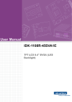
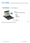
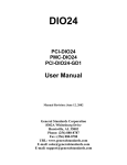
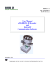
Digital and Analog Input/Output Modules of DFI302
DF32 TO DF40 - DIGITAL OUTPUTS: DC/AC (RELAY)
AND DIGITAL INPUTS: DC (SINK) MODULES
DF32 (1 Group of 8 24 Vdc Inputs and 1 Group of 4 NO Relay Outputs)
DF33 (1 Group of 8 48 Vdc Inputs and 1 Group of 4 NO Relay Outputs)
DF34 (1 Group of 8 60 Vdc Inputs and 1 Group of 4 NO Relay Outputs)
DF35 (1 Group of 8 24 Vdc Inputs and 1 Group of 4 NC Relay Outputs)
DF36 (1 Group of 8 48 Vdc Inputs and 1 Group of 4 NC Relay Outputs)
DF37 (1 Group of 8 60 Vdc Inputs and 1 Group of 4 NC Relay Outputs)
DF38 (1 Group of 8 24 Vdc Inputs and 1 Group of 2 NO and 2 NC Relay Outputs)
DF39 (1 Group of 8 48 Vdc Inputs and 1 Group of 2 NO and 2 NC Relay Outputs)
DF40 (1 Group of 8 60 Vdc Inputs and 1 Group of 2 NO and 2 NC Relay Outputs)
Description
This combo module with DC inputs and relay outputs is designed to drive relays, pilot lamps, valves and
other loads up to 5 A and senses the DC input Voltage and converts them to a True or False logic signal. It
has 1 group of 8 optically isolated 24/48/60 Vdc inputs and 4 relay outputs. The relays can drive loads up to
125 Vdc or 250 Vac. Two screw terminals are reserved for each relay output, though they are isolated
between them.
Vcc
DF32
PWR-A
0
1
3
4
5
6
7
PWR-B
1
2
3
1 G 8x 24 Vdc In & 1 G 4x NO Relays
2
4
smar
201/32 - 1 Group of 8 24 Vdc Digital Inputs & 1 Group of 4 NO Relays
PWR-A
Vext1
In1
In2
1A
2A
3A
Green
Yellow
IMB
4A
5A
6A
7A
8A
9A
GND-A
PWR-B
10A
Green
Vext2
1B
2B
RL1
3B
4B
RL2
5B
Vcc
Yellow
IMB
6B
7B
8B
9B
GNDB
10B
BRN01
Figure 12– Details of the DF32 Module
Technical Specifications
ARCHITECTURE
Number of Groups
Number of Vdc Inputs
Number of Relay Outputs
2
8
4
ISOLATION
Optical Isolation between Groups and IMB
5000 Vac
29