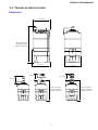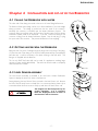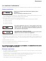
1
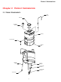
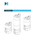
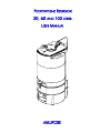
POLYETHYLENE RESERVOIR
30, 60 AND 100 LITERS
USER MANUAL
MILLIPORE
Notice
The information in this document is subject to change without notice and should not be construed as a commitment by
Millipore Corporation. Millipore Corporation assumes no responsibility for any errors that might appear in this document.
This manual is believed to be complete and accurate at the time of publication. In no event shall Millipore Corporation be
liable for incidental or consequential damages in connection with or arising from the use of this manual.
Copyright
© 1998 MILLIPORE CORPORATION. PRINTED IN FRANCE. ALL RIGHTS RESERVED.
THIS BOOK OR PARTS THEREOF MAY NOT BE REPRODUCED IN ANY FORM WITHOUT THE WRITTEN PERMISSION
OF THE PUBLISHERS.
Section 1 Documentation Rev. D - 03/06
Trademarks
Millipore, Elix, Milli-Q and Millipak are registered trademarks of Millipore Corporation.
RiOs is a trademark of Millipore Corporation.
All other trademarks are trademarks of their respective manufacturers.
TABLE OF CONTENTS
Chapter 1
Introduction.......................................................................................1
1-1
USING THIS MANUAL ................................................................................................................. 1
1-2
CONTACTING MILLIPORE ............................................................................................................. 1
Chapter 2
Product Information...........................................................................2
2-1
MAIN COMPONENTS ................................................................................................................ 2
2-2
TECHNICAL SPECIFICATIONS ......................................................................................................... 3
Chapter 3
Unpacking the Reservoir − What’s Inside? ........................................4
Chapter 4
Installation and set-up of the Reservoir .............................................5
4-1
FILLING THE RESERVOIR WITH WATER ................................................................................................ 5
4-2
GETTING WATER FROM THE RESERVOIR ............................................................................................. 5
4-3
LEVEL SENSOR ASSEMBLY ............................................................................................................. 5
4-4
VENT FILTER ............................................................................................................................. 6
4-5
OVERFLOW TUBING AND CHECKVALVE ............................................................................................ 6
Chapter 5
Maintenance......................................................................................7
5-1
MAINTENANCE OF THE OVERFLOW TUBING ...................................................................................... 7
5-2
STORING THE RESERVOIR FOR A LONG PERIOD OF TIME ........................................................................... 7
5-3
SANITIZING THE RESERVOIR .......................................................................................................... 8
Chapter 6
Ordering information ........................................................................9
6-1
CATALOGUE NUMBERS FOR RESERVOIRS ........................................................................................... 9
6-2
CATALOGUE NUMBERS FOR CONSUMABLES ...................................................................................... 9
6-3
CATALOGUE NUMBERS FOR ACCESSORIES ........................................................................................ 9
-i-
INTRODUCTION
Chapter 1 INTRODUCTION
1-1 USING THIS MANUAL
This User Manual is a guide for use during the installation, normal operation, and maintenance of a 30, 60 or 100 Liter PE
Reservoir. ‘Reservoir’ is used in this manual to refer to the 30 Liter PE Reservoir, the 60 Liter PE Reservoir, or the 100 Liter
PE Reservoir unless otherwise noted. It is highly recommended to completely read this manual and to fully comprehend its
contents before attempting normal operation or maintenance of the Reservoir.
1-2 CONTACTING MILLIPORE
INTERNET
The Millipore Internet Site can be used to find addresses, telephone/fax numbers, and other information.
Internet Site Address:
www.millipore.com
www.millipore.com/techservice
MANUFACTURING SITE
Millipore SAS
67120 Molsheim
FRANCE
-1-
PRODUCT INFORMATION
Chapter 2 PRODUCT INFORMATION
2-1 MAIN COMPONENTS
Level
Sensor
Tank Cap
Flat Gasket
with Cap
Reservoir
Front Ball valve
Reservoir
Base
Overflow
Tubi ng
Reservoir
feed port
1/4 inch FNPT
Ball valve
1/2 inch FNPT
Ball valve
Check Valve
-2-
PRODUCT INFORMATION
2-2 TECHNICAL SPECIFICATIONS
DIMENSIONS
392 (15.5)
697 (27.5) Tank 30 l
937 (36.9) Tank 60 l
1357 (53.4) Tank 100 l
415 (16.3)
382 (15)
214 (8.4)
351 (13.8)
190 (7.5)
703 (27.7) Tank 30 l
943 (37.2) Tank 60 l
1367 (53.7) Tank 100 l
-3-
703 (27.7) Tank 30 l
943 (37.2) Tank 60 l
1367 (53.7) Tank 100 l
UNPACKING
Chapter 3 UNPACKING THE RESERVOIR − WHAT’S INSIDE?
Open the Reservoir Shipping Box. Use the checklist below to make sure all items were shipped and are accounted for. It
is highly suggested to become familiar with the items that are shipped since these will be used in the Installation section of
this manual.
Contact Millipore if an item is missing.
Reservoir and base
Front ball valve
Level Sensor cable with jack connector
Lid
Reservoir feed port
ª inch ball valve
∞ inch ball valve
Overflow Tubing and check valve
In the Accessories Bag
Length of Overflow Tubing
6 mm straight tubing connector
Red plug for tubing connector
The following items are
NOT INCLUDED WITH THE RESERVOIR
and need to be ordered separately:
Vent Filter
Connector fittings for the feed water tubing
Feed water tubing to connect to a water system
-4-
INSTALLATION
Chapter 4 INSTALLATION AND SET-UP OF THE RESERVOIR
4-1 FILLING THE RESERVOIR WITH WATER
The other end of this tubing is secured to the source of water filling the Reservoir.
The Reservoir feed water tubing can be cut to allow installation of a 6 mm straight
tubing connector. The tubing is pushed into the two ends of the connector.
Normally the connector is installed near the Water Purification System. The
connector fitting is used later when the flow rate of product water from the Water
Purification System needs to be measured. To do this, remove the tubing at the
connector coming from the Water Purification System. Use the red plug, to plug
the open end of the connector. This prevents the Reservoir from emptying.
> 100 cm
4-2 GETTING WATER FROM THE RESERVOIR
Bring the end of a piece of tubing through the large hole in the back of the base.
Connect the end of this tubing to the ª inch Female National Pipe Thread (FNPT)
ball valve (A). It will be necessary to first place a fitting to this ball valve. This
fitting is not supplied with the Reservoir.
The ∞ inch FNPT ball valve (B) can be used for applications needing large
amounts of water quickly (dishwasher). This valve can be also used to completely
drain the Reservoir of water.
A
B
4-3 LEVEL SENSOR ASSEMBLY
The Level Sensor assembly is intended to be used with a Water Purification
System to display the amount of water in the Reservoir.
During shipping, the Level Sensor float is secured to the Level Sensor rod. Remove
the lid to view the Level Sensor rod and float. It is necessary that the plastic clip is
removed and that the float can move freely up and down the Level Sensor rod.
ATTENTION
The magnet on the float points up for
proper operation. If it is reversed,
then the displayed levels of water in
the Reservoir will be incorrect.
-5-
INSTALLATION
4-4 VENT FILTER
A Vent Filter should be used to filter any air entering the Reservoir. As the Reservoir is being emptied of water, the air
entering the system is filtered through the Vent Filter. It is important that the Reservoir is airtight by securing the lid and that
the check valve on the Overflow Tubing is installed (see below). This allows the air to only go through the Vent Filter.
There are two different Vent Filters available. The catalogue number and description of these Vent Filters are:
TANKMPK01. This Vent Filter is used when the Reservoir is fed with Elix product water. This Vent Filter contains activated
carbon, soda lime and a 0.65 micron (μm) hydrophobic membrane. This Vent Filter is replaced every time the Elix system
Progard pre-treatment pack is replaced. See the Elix/RiOs operating manual for further information regarding Progard
pack replacement.
TANKMPK02. This Vent Filter is used when the Reservoir is fed with RiOs reverse osmosis product water. This Vent Filter
contains two 0.65 (μm) hydrophobic membrane discs inside. This Vent Filter is replaced once-a-year for best results.
TO INSTALL EITHER TYPE OF VENT FILTER:
The plug on the coupling must be removed at installation.
The Vent Filter is mounted to a coupling connector at the top front of the
Reservoir. The thread on the Vent Filter does not need to be taped since there
is a small rubber gasket on the coupling. The Vent Filter should be turned until
it stops against the gasket. Do not over tighten it.
ATTENTION
Do not throw away the Vent Filter
coupling when the Vent Filter is
replaced. The Vent Filter has two
side vent ports. These are not used.
4-5 OVERFLOW TUBING AND CHECKVALVE
The Overflow Tubing is connected between the Reservoir and a check valve
(C). The check valve prevents air from entering the Reservoir through the
Overflow Tubing.
A
Connect the Overflow Tubing to the Reservoir. The end of the Overflow
Tubing (B) is connected to a stem on the back of the Reservoir (A).
B
It is desirable to have at least 45 or more cm vertical distance between the top
of the Reservoir and the check valve.
C
ATTENTION
The check valve has a proper
orientation.
The check valve is
oriented so that water can flow out
the Overflow Tubing but air can not
flow up through the Overflow
Tubing into the Reservoir.
45 cm
-6-
MAINTENANCE
Chapter 5 MAINTENANCE
5-1 MAINTENANCE OF THE OVERFLOW TUBING
The Overflow Tubing should be periodically checked for water inside of it. If there is water inside of it, then the tubing
should be disconnected from the back of the Reservoir. Discard the water in the Overflow Tubing and place the Overflow
Tubing back on the Reservoir.
The Overflow Tubing should be sanitized whenever the Vent Filter is replaced or at least a few times a year. The Overflow
Tubing can be sanitized with bleach (sodium hypochlorite 5% solution) or with household strength hydrogen peroxide
(~ 1.5% solution).
The Overflow Tubing should be replaced if it becomes discolored.
5-2 STORING THE RESERVOIR FOR A LONG PERIOD OF TIME
The reservoir should be drained if it is not used for over one week. The inner wall of the reservoir should be dry during
storage
-7-
MAINTENANCE
5-3 SANITIZING THE RESERVOIR
The Reservoir can be sanitized either through the use of sanitizing chemicals or through the use of an Ultraviolet (UV) light.
CHEMICAL SANITIZATION
ATTENTION
Disconnect any equipment fed by the Reservoir (Milli-Q® systems,
dishwashers...).
Disconnect the ASM if your Reservoir uses one.
1. Fill the reservoir with product water from a Water Purification System. Disconnect the feed water source from the
reservoir by plugging the reservoir feed water tubing connector with the plug.
2. Add enough to obtain a concentration of 100 ppm in the Reservoir.
For example, if you are using an 11.4% Sodium Hypochlorite solution, use the following amounts of bleach:
26 ml for a 30 l tank,
52 ml for a 60 l tank,
88 ml for a 100 l tank.
!
HAZARD
ATTENTION
The Sodium Hypochlorite will form a strong chemical solution when
mixed with water. This solution can be very dangerous for your eyes
and for your skin. Wear Eye Safety Glasses and Laboratory Gloves and
other appropriate safety equipment .
Do not add a chlorine tablet to the reservoir.
If you do not use an 11.4% Sodium Hypochlorite solution, please contact
Millipore for a procedure suitable to your application.
3. Open the valves at the front and at the bottom of the Reservoir for a few seconds in order to sanitize them also.
4. Let the Reservoir soak for at least 12 hours. At the end of this period completely drain the reservoir through the ½ inch
ball valve located at the bottom of the reservoir. Connect the feed water source to the reservoir and allow the reservoir
to fill.
5. Drain and refill the reservoir twice.
6. Reconnect the equipment fed by the Reservoir and replace the Tank Vent Filter.
7. Reconnect the ASM if your Reservoir uses one.
Note: The frequency of sanitization varies depending on use and application. It is recommended to sanitize the Reservoir
at least once a year, if possible at the end of summer.
ULTRAVIOLET SANITIZATION
An Automatic Sanitization Module (ASM) could be used in order to prevent the formation of bio film and the
proliferation of bacteria inside the Reservoir.
The module makes use of the germicidal properties of Ultra-Violet (UV) light at 254 nm produced by a mercury lamp
fitted into the reservoir. The lamp is held in a lid which replaces the existing reservoir closure.
The ASM UV lamp can be turned on one or more times during the day.
Contact Millipore for further information regarding the ASM.
-8-
ORDERING INFORMATION
Chapter 6 ORDERING INFORMATION
6-1 CATALOGUE NUMBERS FOR RESERVOIRS
Description
Catalogue Number
30 L Polyethylene Reservoir
TANKPE030
60 L Polyethylene Reservoir
TANKPE060
100 L Polyethylene Reservoir
TANKPE100
6-2 CATALOGUE NUMBERS FOR CONSUMABLES
Description
Catalogue Number
Advanced Vent Filter (Recommended for Elix® water storage)
TANKMPK01
Standard Vent Filter (Can be used for RiOs™ water storage)
TANKMPK02
6-3 CATALOGUE NUMBERS FOR ACCESSORIES
Description
Catalogue Number
Wall mounting bracket
TANKFIX01
Automatic Sanitization Module (230 V/50Hz)
TANKS50UV
Automatic Sanitization Module (230 V/50Hz) with Water Sensor
TANKS5LUV
Automatic Sanitization Module (120 V/60Hz)
TANKS60UV
Automatic Sanitization Module (120 V/60Hz) with Water Sensor
TANKS6LUV
Distribution Pump (230 V/50 Hz) and Connection Kit
TANKREC50
Distribution Pump (120 V/60 Hz) and Connection Kit
TANKREC51
-9-