1
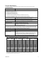
Technical Specifications:
The specifications represent a particular hardware platform. (Application-specific s/w will be provided on request).
Input Specifications
Power Supply Input - Nominal
12 or 24VDC nominal; 9…32 VDC power supply range
Reverse Polarity Protection
Provided
Analog Inputs
Delphi sensors are accepted (see Table 1).
p/n 12146897 coolant/fluid temperature sensor
p/n 12110446 sealed air temperature sensor
p/n 121295956 exposed air temperature sensor
The controller also accepts Honeywell NTC thermistors p/n 50006023-001 (see Table 2).
The user may also select different sensors. Sensors with a linear response are preferred.
Upon ordering, provide details of the selected sensors’ specifications for factory programming the controller.
Temperature Sensor Inputs
3 temperature sensor inputs
User specifies sensor, range of temperature control and setpoints
Sensors’ Ground
Common ground connection provided.
Analog Input 1
0-5V, 0-10 VDC, 4-20 mA, 0-20 mA
Option: 0.25 – 4.75 V potentiometer (5K to 10K) (software feature)
Analog Ground
Analog ground provided
PWM Input
PWM Temperature Input
PWM pulse – normal/reverse polarity up to 3 kHz
Adjustable from 0-100% Duty Cycle (5-95% default)
For example, the controller could interface to a PWM signal from an engine ECM or
an external PWM temperature sensor.
Digital Inputs
The controller accepts switched inputs or other digital inputs. For example, in a hydraulic fan drive application, digital
inputs can be specified to perform these functions: fan direction CW/CCW, climate control ON/OFF, reduce flow (speed
retard); speed advance. Fan reverse has an additional programmed parameter of hold time.
Digital Input 1
Active Low
Digital Input 2
Active Low
Digital Input 3
Active Low
Digital Input 4
Manual Control (MC)
MANUAL CONTROL
Active Low
The manual control input switches the controller into the manual control mode.
The fan speed in this mode is set by the Override Potentiometer or analog input.
If MC is active, the fan speed is determined ONLY by the Override Input.
If MC is passive, the fan speed is determined by the temperature and PWM inputs.
Digital Ground
Common digital ground connection provided (shared as PWM input GND)
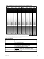
Table 1: Delphi Sensor Temperature vs. Output (Resistance) Table
Temp
[Deg C]
Resistance
[ohms]
Res
[+/- %]
Ref Acc
[+/- Deg C]
Temp [Deg
C]
Resistance
[ohms]
Res
[+/- %]
Ref Acc
[+/- Deg C]
20
3511
2.64
0.60
75
395
2.07
0.60
25
2795
2.50
0.60
80
334
2.04
0.60
30
2240
2.45
0.60
85
283
2.00
0.60
35
1806
2.40
0.60
90
241.8
2.10
0.70
40
1465
2.36
0.60
95
207.1
2.21
0.70
45
1195
2.31
0.60
100
178.0
2.31
0.80
50
980
2.27
0.60
105
153.6
2.42
0.80
55
809
2.23
0.60
110
133.1
2.52
0.90
60
671
2.19
0.60
115
115.7
2.61
0.90
65
559
2.15
0.60
120
100.9
2.68
1.00
70
469
2.11
0.60
Note: The table only applies between 20˚C to 120˚C. Temperatures below this range are set to 20˚C,
and temperatures above this range are set to 120˚C.
TDAX021500
2