1
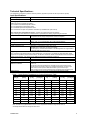
Connections (Typical):
Refer to installation instructions for a specific part number for actual pin out.
Grey Connector
Pin #
1
2
3
4
5
6
7
8
9
10
11
12
Function
+5V Reference (Protected)
Analog Input (Potentiometer)
Analog GND or RS-232 GND (DB-9 Female, pin 5)
Solenoid ANot Used
Battery Battery +
Not Used
Solenoid A+
RS-232 Receive (DB-9 Female, pin 3)
RS-232 Transmit (DB-9 Female, pin 2)
Not Used
TDAX021500
Black Connector
Pin #
1
2
3
4
5
6
7
8
9
10
11
12
Function
Temperature Sensor 1
Temperature Sensor 2
Temperature Sensor 3
Temperature Sensors’ GND
Digital GND or RS-232 GND (DB-9 Female, pin 5)
PWM Input
Digital Input 1
Digital Input 2
Digital Input 3
Digital Input 4 (Manual Mode)
Not Used
Not Used
5