1
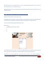
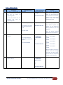
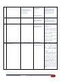
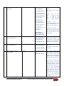
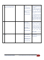
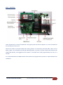
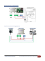
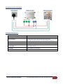
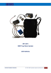
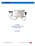
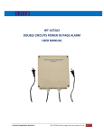
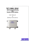
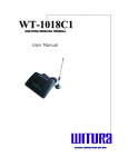
VERSION: 1.2
UPDATED: AUG 2013
WT-1672C
GSM Remote Control Switch
USER MANUAL
WITURA TECHNOLOGY SDN BHD |
WT-1672C GSM Remote Control Switch User Manual V1.9
1
INTRODUCTION
The GSM Remote Control Switch is a wireless remote control on / off switch that connect to the GSM cell
phone network
It has 1 independent relay switches, these can be programmed to switch off or on whenever the GSM
Remote Control Switch is called.
The GSM Control Switch will recognise an authorised telephone numbers calling it and action the call
without answering. Therefore, there is no call charges incurred when calling it.
One Call to the SIM Card Number will switch the device OFF permanently.
Another Call to the SIM Card will switch the device ON permanently.
This system has been developed to minimize the need for over complicated programming.
The GSM Remote Control system supports timer function, the user can set schedule to turn on / off the
switch. For example, put your pump, motor on a schedule. “Turn off in 5 minutes”, “turn on at 17:00, “turn
on 1 year later”
This function is important to use in the renting and leasing industry of electrical appliances, heavy vehicle,
and rental of site equipment to turn off the machines when off hire time completed
This function also important as the reminder to the owner to monitor the SIM Card expiry date. User can
instruct the unit to trigger the relay in the specified times and sent the SMS to the user to keep the SIM Card
active when expiry dates.
When first booting up the system you will see Green LED Lights on the side of the Enclosure and it should
light up when the Network is applied to the unit.
The Green LED is the network Indicator and this will light up when attempting to log on to the network flash
inconsistently until it locates the network.
A Phone Call to the SIM Card Number will now Latch the Relay permanently ON and Switch the device being
Controlled On.
The Status of the Relay will remain as on, until the unit receives a second Call to the Unit of which will now
Latch the Relay Permanently off.
WITURA TECHNOLOGY SDN BHD |
WT-1672C GSM Remote Control Switch User Manual V1.9
2
Both Calls used to Latch the Relay either on or off are automatically disconnected, once the relays are
activated and never incur any Network Call Costs.
Beside calls to switch off or on, the unit also can be permanently switch off and on by sending the unit a text
message command
Step 1 - The simplest set up methods to set up Administrator number
Applied the “KISS Principle”, keep it simple, stupid.
The GSM Remote Control Switch is easy to setup and use. Insert the SIM card, simply use your mobile phone
call to the unit, your mobile phone number will automatically register as the 1st Administrators
You will receive the following SMS message from the unit –
Administrator:
1: 18617185299 (your phone number)
2:
3:
4:
5:
You already finish the set up. Now, you can use your mobile phone call to the SIM Card number switch the
device on permanently. Another call to the SIM Card will switch the device off permanently.
If you do not required to go through details setting, please process to STEP3 – Final Installation and Setup
WITURA TECHNOLOGY SDN BHD |
WT-1672C GSM Remote Control Switch User Manual V1.9
3
Factory Reset
If you required to change the administrator number in the future, simply press the button “FACTORY” at the
mother board until you hear the “du~” . This means the unit back to the factory default
This means you already reset the unit to factory default. Now you can start to call again to set the
administrator.
This method of setting is only allowed to set 1 administrator number. If you wish to set more administrators,
please go to Step 3 – Installation and set up
WITURA TECHNOLOGY SDN BHD |
WT-1672C GSM Remote Control Switch User Manual V1.9
4
Step 2 - Advance Set Up
NO.
Description
1
First Step of programming, you
must enter the factory passwords of
1234
and
go
inside
the
programming mode.
Programming Code
*0*1234#
SMS Texts Respond
You get administrator
privileges!
2013-10-09 00:33 Wed
When you enter *0*1234#, you
enter into the programming
mode. You must perform the
next command in 10 minutes.
If you did not do anything, the
system
will
exit
from
programming mode.
*0*1234*new password#
New password<1212>
Maximum 4 digits of passwords
For example if you need to
change to the new PW of
1212.
2013-10-10 16:07 Thu
If you decide to protect your
privacy, you can change the
factory password to your new
password.
You only can perform the next
commands after
enter into
programming mode
2
Change Password
Function
*0*1234*1212#
Enter the factory password
follow by your new password.
3
Add telephone number into the
admin list.
*1*1*telephone number#
For example set Admin
number 18617185300 into
admin 2
Administrator:
1: 15989427391
2: 18617185300
3:
4:
5:
*1*2*18617185300#
2013-10-10 16:08 Thu
Set Admin Numbers ;
*1*1* - set 1st admin
number
*1*2* - set 2nd admin
number
*1*3* - set 3rd admin
number
*1*4* - set 4th admin
number
*1*5* - set 5th admin
number
Only the number in the list can
receive alarm texts message
and active the relay output.
You can add up to 5 telephone
number into the admin list.
4
Check phone number you
program in the list
*2*
Administrator:
1: 15989427391
2: 18617185300
3:
4:
5:
2013-10-10 16:08 Thu
WITURA TECHNOLOGY SDN BHD |
WT-1672C GSM Remote Control Switch User Manual V1.9
5
5
Delete the admin number in the list.
*3*N#
N = Admin number 1- 5
For example, if you want to
delete admin no 2.
just enter *3*2#
Administrator:
1: 15989427391
2:
3:
4:
5:
Delete Admin Number
Delete 1st admin *3*1#
Delete 2nd admin *3*2#
Delete 3rd admin *3*3#
Delete 4th admin *3*4#
Delete 5th admin *3*5#
2013-10-10 16:08 Thu
6
Check the relay status in ON or OFF
Mode.
*4*
Master relay <ON>
2013-10-10 16:10 Thu
7
Check Signal Strength
*5*
CSQ<28>
2013-10-10 16:11 Thu
The unit will return Master
relay <ON> if the relay is on.
The unit will return Master
relay <OFF> if the relay is off.
You must confirm the signal
strength at site before you
install the unit.
If the signal too weak, the unit
will not function properly.
CSQ 5 – 12 Signal too weak,
system not function
CSQ 13 - 24 Signal Good.
System function well
CSQ 25 – 32 Signal Excellent.
System working well
8
Setting the year, month, day, hours,
minutes, week
*12*YYYYMMDDHHMMX#
Time change OK!
2013-10-10 16:05 Thu
YYYY=4
digit
for
Year
MM = 2 digit for Month
DD = 2 digit for Date
HH = 2 digit for Hour
MM = 2 digit for Minutes
X = 1-7 (Day of the Week)
Example
set
as
*12*2013101016054# which
means 2013-10-10 16:05 Thu
If reprogram the date, it will
take the last as the accurate
date. The date have to be
correct (if setting 2014-2-29 or
2013-11-31) this is the
incorrect date which is not
occur, the system will verify
the date, time, day if correct,
the date have to be after year
2013
WITURA TECHNOLOGY SDN BHD |
WT-1672C GSM Remote Control Switch User Manual V1.9
6
9
Schedule the ON/OFF for the
Master Relay
*13*N*YYYYMMDDHHMM#
Master relay off time:
2013-10-10 16:33
2013-10-10 16:31 Thu
When the programmed
time is reach, the relay is
either on or off, all the
admin will get the reply
SMS as per below.
Since time is up!
Master relay<OFF>
2013-10-10 16:33 Thu
**Note: if the system is
only ON after the
scheduled time, the unit
will still running
accordingly.
System startup!
Master Replay <OFF>
2013-10-10 16:33 Thu
10
Checking the schedule time for
Master Relay ON/OFF
*14*
Master relay on time:
Master relay off time:
2013-10-10 16:33
2013-10-10 16:35 Thu
11
Delete the schedule time for the
Master Relay ON/OFF
*15*N#
Master relay on time:
Master relay off time:
2013-10-14 11:08 Mon
12
SMS Reply Message when the
system ON/OFF
*21*N#
Message switch <ON>
2013-10-10 17:06 Thu
N=0 (Switch Off the Master
Relay)
N=1 (Switch On the Master
Relay)
YYYY=4
MM =
DD =
HH =
MM =
digit
for
Year
2 digit for Month
2 digit for Date
2 digit for Hour
2 digit for Minutes
Example
set
as
*13*0*201310101633# which
means 2013-10-10 16:33 to
switch off the master relay
If reprogram the date, it will
take the last as the correct
date. If you program the date
that already past, the system
will alert you
Checking the schedule time for
Master Relay ON/OFF, when
the time reach, the system will
operate and it will delete the
schedule time automatically.
N=0 (Delete schedule of Relay
OFF Time)
N=1 (Delete schedule of Relay
ON Time)
N=0 means SMS Reply
Message when the system OFF
N=1 means SMS Reply
Message when the system ON
Factory Default as SMS Reply
Message when the system ON
If setting to not receive SMS
Reply Message when the
system OFF, the unit will return
a message indicate successful
setting for the command and it
will no longer sending SMS
reply until the setting of SMS
Reply Message when the
system ON is done. When the
system having the temperature
alert, it will automatically
sending the alert message to
the Admin
WITURA TECHNOLOGY SDN BHD |
WT-1672C GSM Remote Control Switch User Manual V1.9
7
13
To receive SMS Reply Message or
not to receive SMS Reply Message
when the system trigger by phone
call
*22*N#
When sending command
*22*0#
Status switch <OFF>
2013-10-10 17:10 Thu
When sending command
*22*1#
Status switch <ON>
2013-10-10 17:08 Thu
14
Security mode/ Open Mode
*23*N#
When Setting as Security
Mode *23*1#
Mode switch <ON>
2013-10-10 17:13 Thu
When Setting as Open
Mode *23*0#
Mode switch <OFF>
N=1 means after make the
phone call to the system, it will
return the SMS for the status
to the caller
N=0 means after make the
phone call to the system, it will
not return the SMS for the
Status
to
the
caller
Factory Default as return SMS
for the status after make the
phone call
** If you decide not to allow
the system to text you for any
acknowledgement after you
call to the unit. You can switch
OFF the text message. Some
Customer request this function
because texts reply involved
call cost
N=1 means in security mode.
Only allow the number in the
list can text to the unit to
control
the
system.
N=0 means in open mode.
Anybody can call to the unit to
control the system. Please take
note that the Privacy and
Security before you decide to
use
the
Open
Mode
2013-10-10 17:13 Thu
Factory Default is N=1 for
Security Mode
15
SMS Text Message to Switch On/Off
Relay
*24*N#
When Setting as *24*1#
Master relay <ON>
2013-10-10 17:13 Thu
N=1 means switch on the relay
by SMS Message
N=0 means switch off the relay
by SMS Message
When Setting as *24*0#
Master relay <OFF>
2013-10-10 17:13 Thu
WITURA TECHNOLOGY SDN BHD |
WT-1672C GSM Remote Control Switch User Manual V1.9
8
Step 3 - Installation
Insert the SIM card, to access the SIM card carrier gently push the button adjacent to it, insert the SIM card
and carefully close the carrier
Connect the cable to terminals 220V & N ensuring positive is connected to terminal 200V, switch on the
power supply , the red power LED will light indicating power is present, the blue network LED indicator will
initially flash quickly, once logged onto the network , it will flash more slowly approximately one every 3 -4
seconds
It is recommended that the GSM Remote Control Switch be programmed to operate as required before final
installation.
WITURA TECHNOLOGY SDN BHD |
WT-1672C GSM Remote Control Switch User Manual V1.9
9
Connection Details
If you are unsure how to connect the device you wish to control refer to a qualified person
Connector
1
Description
2
3
Digital/Analogue Input
Pulse
Counter
Digital Or
Analogue
Temperature
Input
1
2
3
Relay Connection
NO
NC
COM
4
5
110V-240V Industry
Power Supply
L
N
Note:
1. The Temperature Input is only work with Witura Temperature Sensors
2. The Connect 4 and 5 is inside the Industry Power Supply
Example Connection with Washing Machine
WITURA TECHNOLOGY SDN BHD |
WT-1672C GSM Remote Control Switch User Manual V1.9
10
Example Connection with Coffee Machine
Example Connection with Catering Equipment
WITURA TECHNOLOGY SDN BHD |
WT-1672C GSM Remote Control Switch User Manual V1.9
11
Example Connection with Freezer
Production Specifications
Operation Voltage
Operating Current
Relay Contacts
GSM Frequency MHz
Humidity
Operating Temperature
Physical Size
Protection
Approvals
WITURA TECHNOLOGY SDN BHD |
12 volts DC
Maximum 500mA, typically 55mA
1 x Normally Open and Normally Closed Contacts
maximum switching capacity 20 amps @230v ac per relay
GSM850, GSM900, GSM1800, GSM1900
Less Than 80% RH
-20c to 55c
130 x 100 x 50mm
IP 65 Weather Proof Casing
C.E, FCC, ETSI
WT-1672C GSM Remote Control Switch User Manual V1.9
12
Preparing the SIM card
All new SIM cards have to be registered with the network provider before they can be used, usually by
calling the network provider or registering on their website please refer to the instructions supplied with
your SIM card.
During the registration procedure a confirmation code or text message is usually sent to the SIM cards
telephone number, to be able to read and react to the message you will need to insert the SIM card into an
unlocked mobile phone.
After successfully registering the SIM card, ensure there is sufficient credit on the card for programming
confirmation texts to be sent from the GSM Remote Control Switch.
You MUST ensure that the PIN request is disabled from the SIM card before inserting it into the GSM
Remote Control Switch. If you do not disable the PIN request the GSM Remote Control Switch will not work.
If the PIN request is not disabled and the unit is switched on more than 3 times you will have to reset the
PIN using the PUK code which will have to be obtained from the service provider.
To check the PIN request status of your SIM card, place the card in an unlocked mobile phone, switch the
phone on. If you are able to make calls without entering a PIN number the PIN request is disabled. If a PIN
number is requested refer to the instructions supplied with the SIM card and then look through the phones
options for the ‘disable PIN request’ and disable it.
You MUST disable any voicemail that is set up on the SIM card; the codes shown below are for UK networks
only, please refer to your network operator if outside the UK
Vodafone: 1210 >Send - you will hear ‘order is accepted and confirmed’
O2 - Call 1760 >Send - you will hear ‘order is accepted and confirmed’
T-Mobile - Call 222 and follow instructions
Orange - Call 450 and follow instructions
The SIM card is now ready to use
We recommend that if you are using a ‘pay as you go’ (PAYG) SIM card that you choose to automatically
‘Top-Up’ when the cards credit falls below a certain limit please contact your network provider or visit their
website for more details.
Most but not a using post-paid SIM cards will be de-activated by the network if not used to make an
outgoing voice call or send an SMS text message within a specific period. To prevent this simply send the
GSM Remote Control Switch a text command *0*PW#, then *2*, it will reply by text message, do this once a
month to keep the SIM card active.
WITURA TECHNOLOGY SDN BHD |
WT-1672C GSM Remote Control Switch User Manual V1.9
13
Troubleshooting
Ensure that your DC power supply is connected
1. Red power LED not alight
correctly, positive (+) to terminal 220v and negative (-)
to terminal N. Verify 12 volts is present using a volt
meter
Ensure your SIM card has been activated and that the
2. Blue network LED flashing every one second
PIN request has been disabled. If the unit is in a low
signal strength area consider using an external GSM
and not every 3 seconds
antenna or changing to another network provider
Ensure your telephone number is in the Administrator
3. I am not receiving confirmation test messages
when program the administrators number
list and that sending text messages to your number is
enabled.
Ensure the unit is connected to the GSM network by
4. I am not receiving any text messages when
observing the blue network LED; it should be flashing
once every 3 seconds (see 2 above). Ensure the SIM
initially programming the unit
card has credit
Most but not all PAY SIM cards will be de-activated by
the network if not used to make an outgoing voice call
5. The unit has been working for several months
or send an SMS text message within a specific period.
and has now stopped responding to calls and
To prevent this simply send a txt command *0*PW#,
text commands
then *2*, it will reply by text message, do this once a
month to keep the SIM card active
WITURA TECHNOLOGY SDN BHD |
WT-1672C GSM Remote Control Switch User Manual V1.9
14
Warranty
Witura Technology Sdn Bhd warrantees the WT-1672C GSM Remote Control Switch against defective
parts and workmanship. Witura Technology Sdn Bhd shall, at its option, repair or replace the defective
equipment upon the return of such equipment to any Witura branch. This warranty applies ONLY to
defects in components and workman-ship and NOT to damage due to causes beyond the control of
Witura, such as incorrect voltage, lightning damage, mechanical shock, water damage, fire damage, or
damage arising out of abuse and improper application of the equipment.
Note: Wherever possible, return only the PCB to Witura Service Centres.
DO NOT return the enclosure.
The WT-1672C is a product of
Witura Technology Sdn Bhd
And is manufactured by
Shenzhen Witura Telecommunications Co., Ltd.
WARNING
For safety reasons, only connect equipment with a telecommunications compliance label. This
includes customer equipment previously labelled permitted or certified.
WITURA TECHNOLOGY SDN BHD |
WT-1672C GSM Remote Control Switch User Manual V1.9
15