1
11.0 Cable Routing
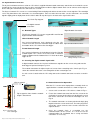
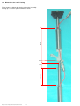
Direction of motion
as the I-P-I chain is
lowered into the casing.
Safety Rope
Fit a safety rope to the I-P-I chain and lower the
sensors slowly into place.
View looking into the
Top of the I-P-I casing
Safety bar
Network Cable
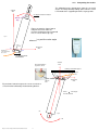
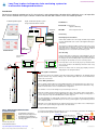
Fitting the I-P-I sensors together
Important Note
Lower the I-P-I sensor into the casing one unit at a time.
Do not drop the I-P-I chain into the casing when
deploying the sensors.
Make sure the safety bar is in place as each individual
I-P-I assembly is lowered into the casing.
Any mechanical shock can damage the sensors.
Fit a safety rope to the I-P-I chain to prevent the
chain from dropping to the bottom of the casing
during installation.
I-P-I
Sensor
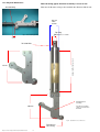
Lower the I-P-I chain slowly into the casing.
At any time that the deployment has to stop, slide the safety
bar into the hole into the I-P-I sensor plug.
Rest the entire mechanical assembly onto the top plug. This
action will prevent the I-P-I chain from sliding into the casing.
Futher information
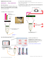
Once the I-P-I chain has been lowered into place
carefully test each sensor is operating using a data logger
or PC. The tests can be made using the Q-Log applications
software.
Fig 33 - Cable Routing Guide & Safety bar installation
Keynes Controls In-place-inclinometer Installation Guide
13