1
Table of contents
Page No
3
Introduction
Warranty Provisions
Successful Measurements
4
Pre-installation Communications Test
Free Applications Software
Media Converters
Part Numbers
5
Mechanical Assembly Operations for the Vertical I-P-I Chain
Spacer Bars
Attaching the In-Place-Inclinometer wheel assembly onto a spacer bar
6
Fastening the spacer bar to the top of the In-place-inclinometer
Minor adjustments to the spacer bar alignment and length
Rod End Baring
7
Digital Network Connection
Network Types
SDI-12
RS-485
Securing the digital network signal cable
Network Connection Operations
8
Axis alignment
Top Mounting Cap
Sensor Connection
9
Securing the In-place-inclinometer chain to the casing tube
10
Sensor Connection Pin-outs - glass seals
Lumberg Connector Pin-outs - Extension cable
Standard signal cable colour codes
Advice for successful measurement operations
Advice for selecting the sensor chain location
Power Supply Rating
11
Interpreting the results
12
Single Sensors or Interfaces Connection
Multiple Sensors or Interface Connection
Typical Q-Log Panel Meter Screen
13
Cable Routing
14
Physical Dimensions
15
Dimensions for 3 m I-P-I string
16
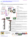
Long Term In-place-inclinometer chain monitoring systems for n-accessible underground locations.
17
Sensor Installation into a flooded I-P-I Casing
18
Long Term Deployment - damp environment - additional waterproofing
Table of Figures
Page NO
Description
3
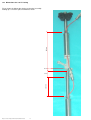
Fig 1
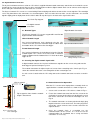
- KEYNES CONTROLS In-place-inclinometer
4
Fig 2 - Basic I-P-I test system setup
5
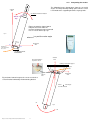
Fig 3 - I-P-I Spacer Bar with plug
5
Fig 4 - I-P-I Spacer bar top piece mount position
5
Fig 5 - I-P-I Wheel assembly mounted on a sensor
5
Fig 6 - I-P-I Wheel assembly mounted on a sensor
5
Fig 7 - I-P-I wheel assembly
6
Fig 8 - Complete I-P-I sensor assembly
6
Fig 9 - Securing the spacer bar to the top of the sensor
6
Fig 10 - Spacer bar locking nut
7
Fig 11 - I-P-I Chain Assembly with network connection
7
Fig 12
7
Fig 13 - Un-sealed network connector
I-P-I Sensor with network connectors
7
Fig 14 - Sealed network connector making a waterproof connection
7
Fig 15 - Connection of the I-P-I to a data logger
8
Fig 16 - I-P-I chain showing a common sensor orientation for all sensors.
8
Fig 17 I-P-I Casing
8
Fig 18 - Sensor orientation
8
Fig 19 - I-P-I casing showing the different sensor orientation options
9
Fig 19 - I-P-I casing showing the different sensor orientation options
9
Fig 20 - Top cap securing bolt
9
Fig 21 - I-P-I Wheel assembly alignment to the casing
9
Fig 22 - Measurement Points
10
Fig 23 - Top mounting cap with securing bolt attached
10
Fig 24 - Sensor Connections
10
Fig 25 Lumberg Connector Pin-outs - Female
10
Fig 26 Lumberg Connector Pin-outs - Male
11
Fig 27 - Understanding Axis for I-P-I chain deployment
11
Fig 28 - Understanding Axis for Ceiling / Horizontal Support
12
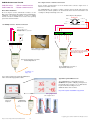
Fig 29 - In-place-Inclinometer connection to an RS-485 Digital Network
12
Fig 30 - USB-RS485-Pro media converter installed on a laptop computer.
12
Fig 31 - USB-RS485-Pro connection to a single I-P-I RS485 model sensor
12
Fig 32 - In-place-inclinometer test system using USB-RS485-Pro media converter and Q-Log applications software
13
Fig 33 - Cable Routing Guide & Safety bar installation
14
Fig 33 - Rod end baring spacing
14
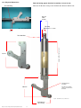
Fig 34 - Standard I-P-I sensor dimensions
15
Fig 35 - Dimensions for a 3 m I-P-I string
16
Fig 36 - PC Data Acquisition system using isolated RS-485 I-P-I Chain
17
Fig 37 - Water filled I-P-I chain with individually wired sensors to the surface.
18
Fig 38 Dow Coning DC4 Silcone Grease,
18
Fig 39 I-P-I Connector on submerged water test
18
Fig 40 - Mated Lumberg I-P-I Connector
18
Fig 41 - Injecting silicon grease
In-Place-Inclinometer User Manual
Keynes Controls In-place-inclinometer Installation Guide
The user manual can be downloaded at
http://www.aquabat.net/downloads/UserManual-IPIv4.pdf
2