1
User's Manual
HDMI-CEC
Demonstration Board
CEC-78K0R/KG3
Tessera Technology Inc.
Date published: June 2010
V1.02
CEC-78K0R/KG3
USER'S MANUAL
Windows and Windows XP are registered trademarks or trademarks of Microsoft Corporation in the United States
and/or other countries.
▪ The information in this document is subject to change without notice.
▪ No part of this document may be copied or reproduced in any form or by any means without prior written consent
of Tessera Technology Inc.
▪ Tessera Technology Inc. does not license assurance or enforcement of intellectual property rights and other rights
of Tessera Technology Inc. and third parties by the use of the products and/or the information in this document.
Tessera Technology Inc. does not assume any liability for infringement of rights of third parties by the use of the
products and/or the information in this document.
▪ Descriptions of circuits, software and other related information in this document are provided for illustrative
purposes in semiconductor product operation and application examples. The incorporation of these circuits,
software and information in the design of a customer's equipment shall be done under the full responsibility of the
customer. Tessera Technology Inc. assumes no responsibility for any losses incurred by customers or third parties
arising from the use of these circuits, software and information.
CAUTION
▪ ・Do not give any physical damage to this equipment such as dropping
▪ ・Do not superimpose voltage to this equipment.
▪ ・Do not use this equipment with the temperature below 0℃ or over 40℃.
▪ ・Make sure the USB cables are properly connected.
▪ ・Do not bend or stretch the USB cables.
▪ ・Keep this equipment away from water.
▪ ・Take extra care to electric shock.
▪ ・This equipment should be handled like a CMOS semiconductor device. The user must take all precautions to
avoid build-up of static electricity while working with this equipment.
▪ ・All test and measurement tool including the workbench must be grounded.
▪ ・The user/operator must be grounded using the wrist strap.
▪ ・The connectors and/or device pins should not be touched with bare hands.
TESSERA TECHNOLOGY INC.
2/31
CEC-78K0R/KG3
USER'S MANUAL
INTRODUCTION
CEC-78K0R/KG3 is designed for users who wish to evaluate HDMI-CEC features with 16-bit
microcontroller 78K0R/Kx3 series from Renesas Electronics.
It is assumed that the readers have been familiar with basics of HDMI and CEC. The overview and
terms are available at "High-Definition Multimedia Interface Specification" in the following web site.
http://www.hdmi.org/manufacturer/specification.aspx
Please use the system with all necessary tests. Tessera Technology Inc. assumes no responsibility for
any losses from the use of CEC-78K0R/KG3.
TESSERA TECHNOLOGY INC.
3/31
CEC-78K0R/KG3
USER'S MANUAL
TABLE OF CONTENTS
1. CEC-78K0R/KG3 ...............................................................................................................................5
1.1
Features....................................................................................................................................5
1.2
Hardware Structure ...................................................................................................................5
1.3
Hardware Specifications ...........................................................................................................6
1.4
Layout of Hardware Functions ..................................................................................................7
1.5
Hardware Functions ..................................................................................................................8
1.5.1 HDMI-CEC Demonstration Board .................................................................................8
1.5.2 TK-78K0R/KG3 Board ..................................................................................................9
1.6
Pin Function List......................................................................................................................11
1.7
Circuit Diagram .......................................................................................................................12
2. SETTINGS FOR SAMPLE DEMONSTRATION PROGRAM...........................................................14
2.1
KEY Settings ...........................................................................................................................14
2.2
LED Settings ...........................................................................................................................15
3. GUI...................................................................................................................................................16
3.1
CEC Viewer Functions ............................................................................................................16
3.2
CEC Viewer Files ....................................................................................................................16
3.3
Connection Example ...............................................................................................................17
3.3.1 Example 1: Monitor Mode ...........................................................................................17
3.3.2 Example 2: Pseudo DVR Mode / Pseudo TV Mode....................................................18
3.4
CEC Viewer Window...............................................................................................................19
3.4.1 Window Overview .......................................................................................................19
3.4.2 "File" Menu .................................................................................................................20
3.4.3 "Menu" Menu ..............................................................................................................21
3.4.4 "Debug" Menu.............................................................................................................22
3.5
Control From CEC Viewer.......................................................................................................23
3.5.1 "Monitor" Tab ..............................................................................................................23
3.5.2 "Replay" Tab ...............................................................................................................25
3.6
Specific Usages ......................................................................................................................26
3.6.1 Switch Settings ...........................................................................................................26
3.6.2 Use As Monitor ...........................................................................................................27
3.6.3 Pseudo Device Sample Program ................................................................................28
3.6.4 Replay Function ..........................................................................................................29
4. DDC MONITOR................................................................................................................................31
4.1
Monitoring DDC on GUI ..........................................................................................................31
TESSERA TECHNOLOGY INC.
4/31
CEC-78K0R/KG3
USER'S MANUAL
1. CEC-78K0R/KG3
In this chapter, feathers and hardware specifications of CEC-78K0R/KG3, 16-bit microcontroller
78K0R/Kx3 series from Renesas Electronics, are described.
1.1 Features
CEC-78K0R/KG3 has following feathers.
- 2 HDMI channels
- 10 general purpose key inputs (AD input)
- Infrared remote control function
- MINICUBE2 connection (on-chip debug, writing on flash memory)
- USB connection with PC
- 2 7segLED
- 15x6 holes universal area
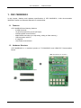
1.2 Hardware Structure
CEC-78K0R/KG3 is a combined product of TK-78K0R/KG3 and HDMI-CEC Demonstration
Board.
HDMI-CEC Demonstration Board
TK-78K0R/KG3
+
・Following connectors are mounted.
TESSERA TECHNOLOGY INC.
5/31
CEC-78K0R/KG3
USER'S MANUAL
1.3 Hardware Specifications
CPU
Clock
Interface
Operating Voltage
TESSERA TECHNOLOGY INC.
uPD78F11166 (78K0R/KG3)
Main system clock: 20MHz, Sub system clock: 32.768KHz
HDMI connector 2ch
MINICUBE2 connector (16pin)
USB (mini B connector)
3.3V (DC 12V input)
6/31
CEC-78K0R/KG3
USER'S MANUAL
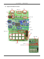
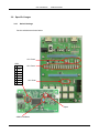
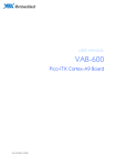
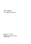
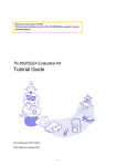
1.4 Layout of Hardware Functions
HDMI1
HDMI3
SSW22,23,21
SW1
JK1
LED1~LED9
JP1
CN3
USB1
SW3
SW4
Y1
U1,2
SW1,2
WRITER1
SSW15,24,14
REM1
SSW19 SSW16
TSW1~10
SSW17,18
SSW1~SSW13,20,25
TESSERA TECHNOLOGY INC.
7/31
CEC-78K0R/KG3
USER'S MANUAL
1.5 Hardware Functions
1.5.1
HDMI-CEC Demonstration Board
- HDMI1, HDMI3
They are HDMI connectors. All the pins of HDMI1 and HDMI3 are connected.
- JK1
JK1 is a connector for AC adapter. Connect the bundled AC adapter here.
- SW1
SW1 is the power switch. Power on when you shift it to ON and then LED1 is lighted.
- LED1
LED1 is Power LED. It is lighted when the power is on.
- LED2-LED9
These are LED that are connected to P7 of CPU. They are lighted when they output Low.
- SSW1-SSW13,20,25
All those 15 switches must be set to "78K0R" side. (default setting)
- SSW14
Not is use.
- SSW15
This must be set to "RIN01 K0R/KG3" side. (default setting)
- SSW16, 17, 18
These must be set to "K0R/KG3" side. (default setting)
- SSW19
This must be set to "K0&K0R/KG3&K0R/KG3-C CECIN/OUT" side. (default setting)
- SSW21-SSW23
These are extended switched for HPD and DDC. Switch them with "Source" or "Sink".
> Set it to "Source" when you use as Monitor mode.
> Set it to "Sink" when you use as Pseudo TV mode.
> Set it to "Source" when you use as Pseudo DVR mode.
TESSERA TECHNOLOGY INC.
8/31
CEC-78K0R/KG3
USER'S MANUAL
- SSW24
Set this to "ON" when you monitor DDC. (default setting)
- TSW1-TSW10
These are use as inputs for general purpose switches. They are connected to A/D
conversion ports.
By pressing the switches, following voltages are input.
Switch CPU Pin CPU Input Voltage
Switch CPU Pin
CPU Input Voltage
TSW1
ANI2
0V
TSW6
ANI3
0V
TSW2
ANI2
0.51V
TSW7
ANI3
0.51V
TSW3
ANI2
0.96V
TSW8
ANI3
0.96V
TSW4
ANI2
1.41V
TSW9
ANI3
1.41V
TSW5
ANI2
1.88V
TSW10
ANI3
1.88V
- WRITER1
This is MINICUBE2 connector.
- REM1
This is the light receiving element for infrared remote control function.
1.5.2
TK-78K0R/KG3 Board
In this section, the hardware functions are briefly described. For details, refer to
"TK-78K0R/KG3 User's Manual".
- CN3
This is a connector for AC adapter, but not in use. Use the JK1 AC adapter connector on
HDMI-CEC Demonstration Board.
- SW1
SW1 is a push-switch that is connected to P120. However, it cannot be used as it is
connected to infrared CEC input function. Do not touch when application is running.
- SW2
SW2 is a push-switch that is connected to P46. However, it cannot be used as it is
connected to infrared remote control function. Do not touch when application is running.
- U1,2
This is 7segLED. U2 is connected to P8.
U1 is connected with the terminal P6 of CPU by way of the solder short putt. This solder
short putt cannot light U1 with CEC-78K0R/KG3 because it has cut it.
- JP1
JP1 sets the CPU power selection. Set this as open. (default setting)
TESSERA TECHNOLOGY INC.
9/31
CEC-78K0R/KG3
USER'S MANUAL
- USB1
This is a USB connector. Use bundled USB cable.
- SW3-1 - SW3-5
These are used as setting the operation mode.
MINICUBE2 is Connected
CEC Viewer is in Use
Switch
(default setting)
1
OFF
2
OFF
SW3
3
OFF
4
ON
5
ON
Debugger ID78K0R-QB is in Use
(bundled with TK-78K0R/KG3)
ON
ON
ON
OFF
OFF
- SW3-6 - SW3-8
These are connected to P50, 51, 52 of CPU.
- SW4
This is the CPU reset switch.
- Y1
This is the CPU operation clock. Do not change this from default setting, 20MHz. The
sample program will not work if it is changed.
TESSERA TECHNOLOGY INC.
10/31
CEC-78K0R/KG3
USER'S MANUAL
1.6 Pin Function List
CN1 Pin Name
1 AVREF0
2
GND
3
P30
4
P04
5 AVREF1
6
P60
7
P61
8
FLMD0
9
VDD
10
(+12V)
11
GND
12
(+12V)
13
VDD
14
RESET
15
VDD
16
(+12V)
17
P64
18
P65
19
P66
20
P67
21
P140
22
P11
23
P01
24
P12
25
P06
26
P05
27
P80
28
P16
29
P17
30
P31
31
P81
32
P82
33
GND
34
EVDD
35
P83
36
P84
37
P70
38
P71
39
P72
40
P73
41
P74
42
P75
43
P76
44
P77
45
P85
46
P86
47
P87
48
P50
49
P51
50
P52
Used For
DDC(CLK)
DDC(DATA)
Connect to WRITE1 Connector(16Pin)
3.3V
GND
3.3V
Connect to WRITE1 Connector(16Pin)
3.3V
CEC-OUT Output
7segLED
DDC(DATA) Monitor
Connect to Over Current(+5V)
GND
7segLED
LED2
LED3
LED4
LED5
LED6
LED7
LED8
LED9
7segLED
7segLED
7segLED
DipSW(SW3-6)
DipSW(SW3-7)
DipSW(SW3-8)
TESSERA TECHNOLOGY INC.
CN2 Pin Name
1
P20
2
P21
3
P22
4
P23
5
P00
6
P131
7
P145
8
P53
9
P57
10
P43
11
P15
12
P14
13
P13
14
P10
15
P111
16
P45
17
P44
18
P27
19
GND
20
EVDD
21
P54
22
P55
23
P56
24
P02
25
P130
26
P42
27
P154
28
P120
29
P144
30
P143
31
P142
32
P141
33
P47
34
P46
35
P41
36
P40
37
P26
38
P25
39
P24
40
P03
41
P62
42
P63
43
P153
44
P152
45
P151
46
P150
47
P110
48
P157
49
P156
50
P155
Used For
KEY input(KEY1~5)
KEY input(KEY6~10)
GND
CEC-IN input
Connect to Remote Control Module
Connect to WRITE1 Connector(16Pin)
Connect to WRITE1 Connector(16Pin)
HPD
11/31
CEC-78K0R/KG3
USER'S MANUAL
1.7 Circuit Diagram
TESSERA TECHNOLOGY INC.
12/31
CEC-78K0R/KG3
TESSERA TECHNOLOGY INC.
USER'S MANUAL
13/31
CEC-78K0R/KG3
USER'S MANUAL
2. Settings for Sample Demonstration Program
2.1 KEY Settings
HDMI
HDMI
AC
Adapter
LED
TK Board
KEY1
KEY2
KEY3
KEY4
Power
Rec
Rec Stop
Mode
KEY6
KEY7
KEY8
KEY9
Play
Revers
Forward
Stop
KEY5
KEY10
e
KEY
KEY1
KEY2
KEY3
KEY4
KEY5
KEY6
KEY7
KEY8
KEY9
KEY10
Used For
Power
Record
Record Stop
Mode Change (Monitor Mode at startup)
Push to change the mode, "Pseudo TV"(LED9 light), "Pseudo DVR"(LED8 light),
"Pseudo TV"(LED9 blinking), "Pseudo DVR"(LED8 blinking), "Monitor".
Please evaluate it by the combination in blinking in lighting when evaluating it
with the board.
(Not in use)
Play
Rewind
Fast-forward
Stop
Select Remote Controller Display (Remote Controller Code / Key Name)
TESSERA TECHNOLOGY INC.
14/31
CEC-78K0R/KG3
USER'S MANUAL
2.2 LED Settings
HDMI
HDMI
AC
Adapter
LED9 LED8 LED7 LED6 LED5 LED4 LED3 LED2 LED1
TK Board
KEY
LED
LED1(green)
LED2(red)
LED3(red)
LED4(red)
LED5(red)
LED6(red)
LED7(red)
LED8(red)
LED9(red)
LED Scroll
Used For
Lighted when the board power is on.
Pseudo device power
Playing
Fast-forwarding
Reversing
Recording
Pseudo DVR mode
Pseudo TV mode
Monitor mode
TESSERA TECHNOLOGY INC.
15/31
CEC-78K0R/KG3
USER'S MANUAL
3. GUI
In this chapter, GUI to control CEC of HDMI from PC (CEC Viewer) is described.
- The sample program (78K0R_Kx3.hex) is pre-installed on the TK-78K0R/KG3.
If you wrote other programs on the system, you can write the sample program
(78K0R_Kx3.hex) again by using following tools.
- Flash memory programmer for MINICUBE2 "QB-Programmer" or debugger
"ID78K0R-QB".
- This sample program works only if 20MHz oscillator is mounted on TK-78K0R/KG3.
- The remote control receiving function of this sample program (78K0R_Kx3.hex) supports only
NEC format.
- CEC Viewer works with Microsoft Excel. (operation check has been done on Excel 2000 and
Excel 2003)
3.1 CEC Viewer Functions
CEC Viewer has following functions.
- Monitor sending/receiving CEC data
- Send specific commands from user input
- Pre-set command data, 20 KEY
- Output log data with Excel format
- Reproducing function by loading log data with Excel format
3.2 CEC Viewer Files
File
CECViewer.exe
command.xls
cecviewer.ini
TESSERA TECHNOLOGY INC.
Description
Start CEC Viewer by executing this file.
CEC command (Opcode) data file. With using this file, you can add
new Opcode.
Since the program retrieves the command data from this file, do not
close this file while CEC Viewer is running.
Pre-set key data that is registered with GUI is stored in this file.
16/31
CEC-78K0R/KG3
USER'S MANUAL
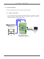
3.3 Connection Example
Connection examples of the board for using CEC Viewer are described.
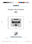
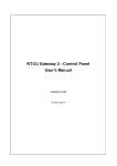
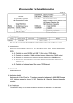
3.3.1
Example 1: Monitor Mode
You can monitor the data communication between devices by connecting the devices
through the board. Following figure shows the connection example to monitor the
communication between TV and recording device.
HDMI Cable
Recording Device
Recording Device
USB Cable
PC
TV
TV
TESSERA TECHNOLOGY INC.
CEC-78K0R/KG3 Board
(Monitor Mode: LED Scroll)
17/31
CEC-78K0R/KG3
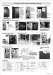
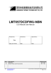
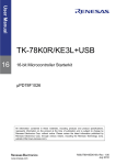
3.3.2
USER'S MANUAL
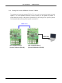
Example 2: Pseudo DVR Mode / Pseudo TV Mode
To operate the board as a pseudo DVR or TV, you need to connect the board to board
together. You can reproduce functions, such as turning on the power of pseudo TV
automatically by turning on the power of pseudo DVR, and turning off the power of pseudo
DVR automatically by turning off the power of pseudo TV.
HDMI Cable
USB Cable
PC
CEC-78K0R/KG3 Board
(Pseudo TV Mode: LED9 ON)
TESSERA TECHNOLOGY INC.
CEC-78K0R/KG3 Board
(Pseudo DVR Mode: LED8 ON)
18/31
CEC-78K0R/KG3
USER'S MANUAL
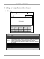
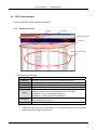
3.4 CEC Viewer Window
In this section, CEC Viewer window is explained.
3.4.1
Window Overview
Menu Bar
Shortcut Key
Multipurpose Window
Preset Keys
CEC Communication Data
CEC Communication Data
No
Communication orders
Remocon
Remote controller code or remote controller code name
Initiator
Initiator Address name *
Destination
Destination Address name *
Opcode
Opcode name and its operand structure *
Frame communication result
It displays data on odd byte and EOM+ACK on even byte.
Data
It displays "e" when it has EOM, otherwise "-".
It displays "a" when it has ACK, otherwise "n".
Interval time between CEC communication (or DDC communication
Interval[ms]
offered as optional function)
Date & Time
Date and time when it gets the frame data
*
It gets the information from "command.xls". If you close this file, it will not be able to
display the logical address and Opcode.
TESSERA TECHNOLOGY INC.
19/31
CEC-78K0R/KG3
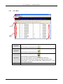
3.4.2
USER'S MANUAL
"File" Menu
Select All
Select
Specific
Item
★
Clear log data displaying.
Log New
It is the same as the shortcut key
.
This does not work with current version of CEC Viewer.
Log Open
.
It is the same as the shortcut key
Save the current log data with Excel format.
Log Save
End
TESSERA TECHNOLOGY INC.
.
It is the same as the shortcut key
*You can select specific rows by checking the check box.
*You can select all rows by checking the check box above "No".
Please select * on the No row again after clicking the area of * once
when all not selecting it.
Close CEC Viewer.
20/31
CEC-78K0R/KG3
3.4.3
USER'S MANUAL
"Menu" Menu
COM Config (Settings for UART communication)
Select the COM port that is assigned for TK-78K0R/KG3C.
COM Port
(COM Port 1-19)
Select from 9600, 14400, 19200, 38400 (default), 57600, 115200,
Bit rate
128000. (Select the default setting, 38400)
Data Bit
Fixed with 8 bit.
Parity
Fixed with None.
Stop Bit
Fixed with 1 bit.
TESSERA TECHNOLOGY INC.
21/31
CEC-78K0R/KG3
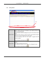
3.4.4
USER'S MANUAL
"Debug" Menu
Staus
Monitor Start
Replay Start
Start monitoring CEC.
When it starts monitoring, the bottom of the window becomes red
color to show RUN status.
Communication results are displayed only when the status bar shows
RUN.
Select this menu when you wish to monitor communication between
devices or to send commands from CEC Viewer.
To stop monitoring, select this menu again. It toggles like RUN,
STOP, and RUN.
It is the same as the shortcut key
.
Replay the CEC communication based on log data saved with Excel
format.
Set replay tag properly and execute.
*For detail about replay function, refer to "3.6.4 Replay Function"
It is the same as the shortcut key
TESSERA TECHNOLOGY INC.
.
22/31
CEC-78K0R/KG3
USER'S MANUAL
3.5 Control From CEC Viewer
CEC data can be sent from CEC Viewer.
3.5.1
"Monitor" Tab
It sends user defined CEC data from preset keys.
Select "Monitor(1)" Tab for KEY
Following "Preset KEY Config" screen is displayed by clicking "SET" key.
<KEY Setting>
Select Header and Opcode for the sending CEC data at combo box shown above red
area. (You can also enter it at the KEY input area directly.)
1. Select sender's initiator address at "Initiation".
2. Select receiver's destination address at "Destination".
3. Select the class of sending Opcode at "Class".
4. Select Opcode at "Opcode"
5. Move the cursor at the first byte of specific KEY, and click "Create Command" key.
Header and Opcode will be automatically set.
6. Enter Operand for Opcode at the KEY input area directory as needed.
TESSERA TECHNOLOGY INC.
23/31
CEC-78K0R/KG3
USER'S MANUAL
Also, captions of KEY on CEC Viewer can be changed.
Change the caption to "TV_OFF", then set the data [10] [36].
The caption of KEY1 is changed to "TV_OFF".
By clicking "TV_OFF" key, it outputs CEC data ([10][36]), then the log data is displayed.
TESSERA TECHNOLOGY INC.
24/31
CEC-78K0R/KG3
3.5.2
USER'S MANUAL
"Replay" Tab
It loads monitoring information, the board becomes a unit on the CEC, and then it replays the
same CEC command communication.
For detail, refer to "3.6.4 Replay Function".
TESSERA TECHNOLOGY INC.
25/31
CEC-78K0R/KG3
USER'S MANUAL
3.6 Specific Usages
3.6.1
Switch Settings
Set the switches as shown below.
ALL Down
SW3
8 OFF
7 OFF
6 OFF
5 ON
4 ON
3 OFF
2 OFF
1 OFF
ALL Down
ALL Down
Open
20MHz Oscillator
TESSERA TECHNOLOGY INC.
26/31
CEC-78K0R/KG3
3.6.2
USER'S MANUAL
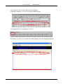
Use As Monitor
When CEC Viewer is just started, the color of status bar is white to show "Ready". At this
status, it does not display any CEC data.
Click "Start" button to start monitoring by CEC Viewer.
The status bar becomes red to show "Run" status.
With this status, CEC communication data between the boards will be displayed.
Click "Start" button again to stop monitoring ("Ready" status).
TESSERA TECHNOLOGY INC.
27/31
CEC-78K0R/KG3
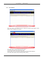
3.6.3
USER'S MANUAL
Pseudo Device Sample Program
You just need to run CEC Viewer to use the Pseudo Device mode that is the same as
Monitoring mode.
Click "TSW4(KEY4)" to select Pseudo Device (TV/DVR) mode. The multipurpose window
displays the status of current pseudo device.
This is the example when you press power key with pseudo DVR mode.
The multipurpose window displays "Power ON" to show the pseudo DVR is turned up.
Mode
Pseudo TV
Mode
Pseudo DVR
Mode
TESSERA TECHNOLOGY INC.
Multipurpose Window
Power ON
Power OFF
HDMI Input Change
Power ON
Power OFF
PLAY
STOP
FORWARD
REVERSE
REC
REC STOP
PLAY(Recording)
STOP(Recording)
FORWARD(Recording)
REVERSE(Recording)
Status
Power ON
Power OFF
TV input is switched to HDMI input
Power ON
Power OFF
Playing
Stopped
Fast-forwarding
Rewinding
Recording
Recording Stop
Playing While Recording
Stopped While Recording
Fast-forwarding While Recording
Rewinding While Recording
28/31
CEC-78K0R/KG3
3.6.4
USER'S MANUAL
Replay Function
1. Monitor replaying communication. Operation mode should be monitor mode (LED is scroll
status on the board).
2. Select the saving rows from monitoring CEC communication data and check the check
boxes.
Then, click "Save" button to save the data in a file。
Save Logs
Check
3. Next, replay the saved CEC communication data. Click "Open Script" button on "Replay"
tab and select the log file that you have just saved before.
Replay Tab
Actual
Communication
Data
TESSERA TECHNOLOGY INC.
Load
Log
File
Loaded
Log
Data
29/31
CEC-78K0R/KG3
USER'S MANUAL
4. Set the logical address to alternative address for the board. Specify the address at "My
Logical Address".
Specify
Address
5. The preparation for the replay process is completed. Now, you can start the replay by
clicking "Replay" button.
* The replay operation will be terminated when it received the data that is different from
the log data. Use the replay function with the same environment as the one when you
save the log data.
<Example>
When you replay the TV power operation, make sure the elapsed time after you turned
off the TV power is the same as the time in the log file.
Replay
Button
TESSERA TECHNOLOGY INC.
30/31
CEC-78K0R/KG3
USER'S MANUAL
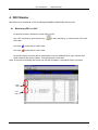
4. DDC Monitor
DDC data can be monitored on GUI by setting SSW24[DDC MONITOR] switch to ON.
4.1 Monitoring DDC on GUI
No special process is needed to monitor DDC on GUI.
Like CEC monitoring, click shortcut key
DDC data.
Row with
means that it is DDC data.
Row with
means that it is CEC data.
to start monitoring. It monitors both CEC and
As the data format, it stores data on odd number rows and ACK/NACK on even number rows.
When it detects the Start Condition, it recognizes as the next data.
(Also, in the case of restarting that it does not get Stop Condition, it recognizes as the next data)
DDC
Data
CEC
Data
TESSERA TECHNOLOGY INC.
31/31