1
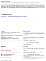
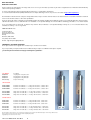
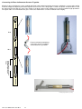
Reference Position
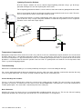
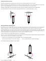
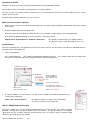
3 m gauge length
2 m gauge length
1 m gauge length
The image opposite shows the standard length of the I-P-I sensors
and gauge rods that are used for the sensor chain.
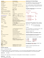
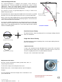
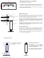
Direction of movement
For the optimum results the casing should be installed with one set
of grooves aligned into the expected direction of motion.
The wheels are used to align the sensor inside the gauge tube.
Vertical In-Place-Inclinometer
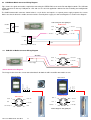
The in-place-inclinometer sensor chain consists of a series of
inclinometers and a gauge case. Generally the sensors are connected to
a data recording device such as a stand-alone logger unit or laptop for
storage and display of the inclinometer data The Keynes Controls Q-LOG
software is a good companion to the I-P-I sensor chain and gives easy
access to the data and sensor configurations.
.The inclinometer casing provides easy access to the sub-surface
movement, controls the orientation of the sensors, and moves with the
surrounding landscape.
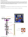
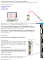
In vertical installations the gauge tube is mounted into a bore hole, and
this bore-hole passes vertically through the suspected zone of movement
into stable ground. The stable end of the I-P-I chain typically acts as the
reference point for any future measurement points. One set of groves in
the casing is always aligned into the expected direction of movement of
the ground.
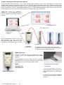
Casing
In-fill around the
casing tube.
The sensor casing tube is secured into the bore hole using sand and grout
which is tampered to fill in the excess space between the land under
investigation and the casing. Any movement of the land is directly
transmitted to the gauge casing and so to the sensors contained inside.
The casing is secured to make sure there is no movement apart from that
induced by the landscape under investigation.
The sensors are intelligent and provide data values directly in engineering
units of mm/m by default. The output value can be converted directly into
displacement of mm by scaling the output value by the gauge rod length.
Displacement = Output mm/m x Gauge Rod length (m).
Stable Ground
I-P-I User Mnaual V4 Jan 2013
14