1
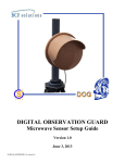
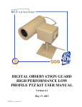
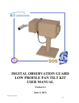
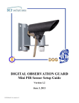
DIGITAL OBSERVATION GUARD
Dual Technology Sensor Setup Guide
Version 1.0
June 3, 2013
DS-DT-Kit-2-v1_manual-1
Table of Contents
Dual Technology Sensor Kit Description ............................................................................................................................... 2
Setting up the Sensors ............................................................................................................................................................. 3
Connecting the Sensors to the Cameras .............................................................................................................................. 4
Mounting the Sensors on a Tripod ...................................................................................................................................... 4
Mounting the Sensors on a Wall ......................................................................................................................................... 5
Mounting the Sensors to a Pole........................................................................................................................................... 6
Sensor Adjustment and Fine Tuning....................................................................................................................................... 8
Perform Walking Test ......................................................................................................................................................... 8
Removing Sensor Cover to Adjust Settings ........................................................................................................................ 9
Adjusting Sensor Range Performance .............................................................................................................................. 10
Adjusting Sensor Sensitivity Performance........................................................................................................................ 10
Pet Alley Mode ................................................................................................................................................................. 10
Disabling LED .................................................................................................................................................................. 11
DOG Base Station Software Configuration of Alarms ......................................................................................................... 11
Alarm Display During Operation.......................................................................................................................................... 12
Contact Info .......................................................................................................................................................................... 13
Replacement Parts ................................................................................................................................................................. 13
Table of Figures
Figure 1: Dual Technology Sensor Coverage Pattern ............................................................................................................. 2
Figure 2: Dual Technology Sensor Kit and Military Case ...................................................................................................... 3
Figure 3: Dual Technology Sensor Kit Identification Label ................................................................................................... 3
Figure 4: Connecting Dual Technology Sensor to DOG Camera ........................................................................................... 4
Figure 5: Tripod Mounting Hardware ..................................................................................................................................... 4
Figure 6: Tripod Mounting Procedure .................................................................................................................................... 5
Figure 7: Wall Mounting Hardware ........................................................................................................................................ 5
Figure 8: Wall Mounting Procedure ....................................................................................................................................... 6
Figure 9: Pole Mounting Hardware ........................................................................................................................................ 7
Figure 10: Pole Mounting Procedure ...................................................................................................................................... 7
Figure 11: Installing Audible Tester for Walk Test ................................................................................................................ 8
Figure 12: Sensor Steady State (No Alarms) .......................................................................................................................... 8
Figure 13: Alarm Sensor State ................................................................................................................................................ 9
Figure 14: Individual PIR and Microwave Sensor States (No Alarms) .................................................................................. 9
Figure 15: Removing Sensor Circuitry for Performance Adjustments ................................................................................... 9
Figure 16: Sensor Range and Sensitivity Settings ................................................................................................................ 10
Figure 17: Pet Alley Mode DIP Switch ................................................................................................................................ 11
Figure 18: LED Illumination DIP Switch ............................................................................................................................. 11
1
Figure 19: Find Alarm Configuration Menu ......................................................................................................................... 12
Figure 20: Configuring Channel Alarm Inputs for Normally Closed ................................................................................... 12
Figure 21: Sensor Alarm Indicators ...................................................................................................................................... 12
Dual Technology Sensor Kit Description
The Dual Technology Sensor is an outdoor sensor designed to provide volumetric protection in a wide variety
of indoor and outdoor applications. The sensor uses the unique combination of Microwave and Passive Infrared
technologies and is configured so that both technology portions must activate simultaneously for the sensor to
alarm. The microwave portion detects the motion of an intruder, whereas the passive infrared portion detects a
change in infrared radiation. When both technologies activate at the same time, the sensor initiates an alarm
condition. The sensor operates with a maximum detection range out to 30m (100ft.) as shown in the figure
below.
Figure 1: Dual Technology Sensor Coverage Pattern
2
The Dual Technology Sensor KIT is an accessory kit for installation with the DOG Base Kit. Each Dual
Technology Sensor Kit contains 2 dual technology sensors along with the necessary mounting hardware and
associated accessories as shown in the figure below.
Figure 2: Dual Technology Sensor Kit and Military Case
Each case can be identified by a decal just above the handle as shown in the figure below.
Figure 3: Dual Technology Sensor Kit Identification Label
Setting up the Sensors
With the DOG system, all sensors are paired with cameras to provide direct visual assessment of each alarm.
The Dual Technology Sensor receives its power from the DOG remote camera module and transmits its alarms
back to the DOG Base Station via the camera module also. The sensors plug into the sensor ports located on the
side of the DOG remote module.
3
Connecting the Sensors to the Cameras
To connect the sensor to the remote camera module, simply remove the cap on the remote module sensor port as
shown in the figure below. Line up the pins (and notch) on the sensor connector and push the sensor connector
into the mating connector on the camera module. Twist the ring at the end of the sensor connector clockwise to
lock and seal the connector in place.
Figure 4: Connecting Dual Technology Sensor to DOG Camera
Mounting the Sensors on a Tripod
To mount the Dual Technology Sensor on a tripod remove the sensor, ‘L’ bracket, and mounting hardware bag
from the transit case.
Figure 5: Tripod Mounting Hardware
Begin by attaching the ‘L’ Bracket to the tripod using the threaded 3/8-16 hole on the bracket. Next remove the
cap screw and washer from the bottom of the sensor enclosure. Make sure to leave the lock washer in place as
it prevents the sensor from turning once assembly is complete. Place the sensor on top of the ‘L’ bracket and
attach the two together using the cap screw and washer. Use the Allen key provided in the mounting hardware
4
bag to fully tighten the screw to securely attach the sensor to the bracket. Once the sensor is securely mounted
to the tripod the tilt angle of the sensor can be adjusted by loosening the cap screw on the side of the sensor.
Figure 6: Tripod Mounting Procedure
Mounting the Sensors on a Wall
To mount the Dual Technology Sensor on a wall remove the sensor, ‘L’ bracket, and mounting hardware bag
from the transit case.
Figure 7: Wall Mounting Hardware
5
The hardware mounting bag contains several different types of screws to allow for mounting the sensor in
various materials such as wood or concrete. The figure below shows a wall installation using concrete bolts.
Begin by drilling two holes into the concrete just large enough for the reinforcing concrete bolt to fit into. It is
recommended to first place the wall mounting bracket against the wall and mark where the two holes need to be
drilled. Next take two of the appropriately sized screws and washers from the hardware mounting bag and
screw the ‘L’ bracket onto the wall. Once the ‘L’ bracket is firmly attached to the wall place the sensor on top
of the bracket and use the cap screw and washer to securely fasten the sensor to the bracket. An Allen key is
provided in the hardware mounting bag to fully tighten the cap screw.
Figure 8: Wall Mounting Procedure
Mounting the Sensors to a Pole
To pole mount the Dual Technology Sensor remove the sensor, ‘L’ bracket, pole mounting brackets (x2), 8”
bolts (x2), and mounting hardware bag from the transit case.
6
Figure 9: Pole Mounting Hardware
Begin by attaching the ‘L’ bracket to one half of the pole mount bracket using two ¼-20 screws and washer.
Next take the other half of the pole mount bracket and sandwich the mounting hardware around the pole. Use
the two 8” bolts to securely tighten the pole mounting brackets to the pole. Once the pole mount bracket is
securely fashioned to the pole remove the cap screw and washer from the bottom of the sensor enclosure. Make
sure to leave the lock washer in place as it prevents the sensor from turning once assembly is complete. Place
the sensor on top of the ‘L’ bracket and attach the two together using the cap screw and washer. Use the Allen
key provided in the mounting hardware to fully tighten the cap screw.
Figure 10: Pole Mounting Procedure
7
Sensor Adjustment and Fine Tuning
In order to assure the best possible protection and lowest false alarm performance of the sensor, it is highly
recommended to perform a walk test once the sensor has been installed. The sensor provides both range and
sensitivity controls to allow for fine tuning the sensor. Refer to the range and sensitivity adjustment sections
below for instructions on how to adjust these settings.
Perform Walking Test
Power up the sensor and wait approximately two minutes for the sensor to initialize. During this time the LEDs
on the front of the sensor will flash on and off. It is recommended to plug in the included audible tester into the
front of the sensor, as shown in the figure below. Remember to remove the audible tester once the walk test has
been completed.
Figure 11: Installing Audible Tester for Walk Test
Once both the Microwave and Passive Infrared LED’s turn a steady Green and the optional audible tester is
silent, the sensor has stabilized and is ready for the walk test.
Figure 12: Sensor Steady State (No Alarms)
Walk into the surveillance area while observing the sensor LED’s. Verify that both green LED’s turn off
followed by the Microwave LED turning Yellow and the Passive Infrared LED turning Red. The optional
audible tester will emit a continuous tone. In addition, the Master Alarm LED will turn Red notifying the
walker that an alarm signal is being generated.
8
Figure 13: Alarm Sensor State
Depending on which technology is triggered first it may be possible that only one LED goes into an alarm state.
When the sensor only detects a change in the infrared radiation the Passive Infrared LED turns Red, while the
Microwave LED stays Green. The optional audible tester will emit a slow beeping tone. When the sensor only
detects motion the Microwave LED turned Yellow, while the Passive Infrared LED stays Green. The optional
audible tester will emit a fast beeping tone. Since the sensor requires that both technologies be triggered to
enter into an alarm state no master alarm signal is generated for either case.
Figure 14: Individual PIR and Microwave Sensor States (No Alarms)
Once the Walk Test has been performed and the sensor is operating with the optimal settings remove the
audible tester if used.
Removing Sensor Cover to Adjust Settings
If during the walk test it has been determined that the sensor settings need to be adjusted for optimal
performance it will be necessary to remove the sensor circuitry from its enclosure. Begin by removing the four
screws on the front of the sensor.
Figure 15: Removing Sensor Circuitry for Performance Adjustments
9
Adjusting Sensor Range Performance
The range control switch adjusts the overall distance of the sensor’s detection area. The range values are given
in percentages. A setting of 100 means the sensors will detect objects at the maximum distance of 30m (100ft),
while a range setting of 50 means the sensor will only have a detection range of 15m (50ft). The sensor is
configured with a default range setting of 100. However, it is recommended to set the range performance to the
lowest setting to attain the desired range for a given scene. This helps to reduce nuisance alarms from objects
outside the area of interest.
Figure 16: Sensor Range and Sensitivity Settings
Adjusting Sensor Sensitivity Performance
The sensitivity control switch adjusts the amount of movement required for an alarm condition. The higher the
setting value (maximum of 10) the more sensitive the sensor becomes requiring less detected motion before an
alarm is triggered. The sensitivity control is the most critical adjustment for false alarm rejection. It is
recommended to start at a relatively low sensitivity and slowly increase the sensitivity until false alarms begin
to occur and then back the sensitivity by one value. The sensor is configured with a default sensitivity setting of
4.
Pet Alley Mode
Pet Alley Mode is used in environments where there is an abundance of birds and small animals that
continuously set off false alarms. In Pet Alley the overall sensitivity is reduced by approximately 20%. In
addition, the detection speed is significantly reduced so that a vehicle or person traveling at a rate of speed
greater than 1 m/s (3.6 km/h) may not be detected. The sensor’s default configuration is with Pet Alley Mode
turned ON. If during the Walk Test it is determined that the sensor is not sensitive enough or the threat of false
alarms from animals is not an issue, this mode can be turned off by flipping the dip switch to OFF as shown in
the figure below.
10
Figure 17: Pet Alley Mode DIP Switch
Disabling LED
Once the Walk Test has been performed and the sensor is properly configured to the optimal performance
settings it may be desired to turn off the Walk Test LED’s to allow for more covert operation. With the sensor
cover removed slide the LED’s switch right to the OFF position to disable the sensor LEDs on the front of the
enclosure.
Figure 18: LED Illumination DIP Switch
DOG Base Station Software Configuration of Alarms
Once the sensors are connected the DOG Base Station software must be configured to support normally closed
alarm inputs. To get to the alarm input configuration screen click on the Event icon from the main menu and
then select the Per Channel Config menu as shown in the figure below.
11
Figure 19: Find Alarm Configuration Menu
Select the channel that you would like to configure in the Channel Select list and then select N/C in the Alarm
In list. Press the ESC key on the DVR front panel or click on the red circle with the X in the upper right hand
corner if you are using a USB mouse, in order to save the settings and escape to the next higher level menu.
Repeat this operation for each channel that you would like to configure. When finished, push the ESC button
repeatedly all the way back to the main menu.
Figure 20: Configuring Channel Alarm Inputs for Normally Closed
Alarm Display During Operation
A red A will appear on the screen when there is a sensor alarm as seen in the figure below.
Figure 21: Sensor Alarm Indicators
12
Contact Info
For questions or support please see our website at: www.bcfsolutions.net or contact:
[email protected], 703-956-9088.
For user manual or other technical downloads go to the customer tab on the website and login with the
following: user: customer password: 2004-S4Tech
Replacement Parts
The following replacement parts may be ordered for the DOG Dual Technology Sensor Kit. Credit card orders
are accepted. Please contact S4 for order information.
Part No.
Description
DRP-DTS
Dual technology microwave sensor replacement.
DRP-DTS-BK Dual technology microwave sensor mounting bracket.
13