1
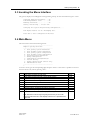
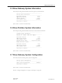
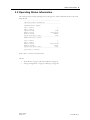
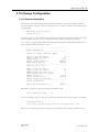
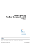
User Manual Anybus® X-gateway Doc.Id. HMSI-168-101 Rev. 1.20 Connecting DevicesTM +$/067$'&+,&$*2.$5/658+(72.<2%(,-,1*0,/$1208/+286(&29(175<381(&23(1+$*(1 HMS Industrial Networks Mailing address: Box 4126, 300 04 Halmstad, Sweden Visiting address: Stationsgatan 37, Halmstad, Sweden E-mail: [email protected] Web: www.anybus.com Table of Contents Table of Contents Preface About This Document Important User Information................................................................................................................... 1 Document History ................................................................................................................................... 2 Summary of Recent Changes (1.13 ... 1.2) ....................................................................................... 2 Revision List.................................................................................................................................... 2 Conventions & Terminology .................................................................................................................. 2 Support....................................................................................................................................................... 3 Chapter 1 About the Anybus X-gateway Introduction .............................................................................................................................................. 4 Functional Overview................................................................................................................................ 4 External View............................................................................................................................................ 5 Installation ................................................................................................................................................. 6 DIN-rail Installation....................................................................................................................... 6 Power............................................................................................................................................... 6 Network Installation........................................................................................................................ 6 Anybus X-gateway Doc.Rev. 1.20 Doc.Id. HMSI-168-101 1-II Chapter 2 Basic Operation Data Exchange.......................................................................................................................................... 7 Status & Diagnostics ................................................................................................................................ 8 Status Word .................................................................................................................................... 8 Live List (Master Configurations Only) ........................................................................................... 9 Network Specific Status ................................................................................................................... 9 Controlling the Gateway from the Network...................................................................................... 10 Control Word ................................................................................................................................ 10 Network-specific Controls............................................................................................................... 10 Data Mapping.......................................................................................................................................... 11 Error Handling........................................................................................................................................ 12 Chapter 3 Gateway Config Interface General Information .............................................................................................................................. 13 Communication Settings ....................................................................................................................... 14 Invoking the Menu Interface................................................................................................................ 15 Main Menu............................................................................................................................................... 15 Show Gateway System Information .................................................................................................... 16 Show Fieldbus System Information .................................................................................................... 16 Show Gateway System Configuration ................................................................................................. 16 Show Fieldbus System Configuration ................................................................................................. 17 Operating Status Information .............................................................................................................. 18 Change Configuration............................................................................................................................ 19 General Information....................................................................................................................... 19 Settings .......................................................................................................................................... 20 Configuration Upload/Download ....................................................................................................... 21 Change Operation Mode....................................................................................................................... 22 Chapter 4 Connectors and Cables Power Supply .......................................................................................................................................... 23 Gateway Config Interface ..................................................................................................................... 23 Null Modem Cable Schematic.............................................................................................................. 23 Appendix A Mechanical Drawings Appendix B Technical Specification Power........................................................................................................................................................ 25 Protective Earth and Shielding............................................................................................................. 25 Temperature ............................................................................................................................................ 25 Relative Humidity................................................................................................................................... 25 EMC Compliance ................................................................................................................................... 25 Anybus X-gateway Doc.Rev. 1.20 Doc.Id. HMSI-168-101 Chapter 2 2. Basic Operation 2.1 Data Exchange Each of the two network interfaces exchange data on their networks through two buffers. The gateway forwards the data between these buffers as shown below. Note that this process is separate from the network data exchange; while the gateway ensures data consistency (where applicable), it does not include any built-in mechanisms for synchronisation between the two networks. Network Interface 1 Data From Network 1 Data From Network 1 Network Interface 2 Network 2 Network 1 Data From Network 2 Data From Network 2 Each buffer holds up to 512 bytes of data, which is the theoretical upper limit for the number of bytes that can be exchanged in each direction. Note, however, that the actual number of bytes that can be exchanged is very network dependent. Besides network I/O, these buffers are optionally also used to provide access to network status information, and to control various aspects of the gateway. This may be general diagnostic information (called the ‘Status Word’), a list of active slaves (known as the ‘Live List’), or other network-specific status information. A dedicated “Control Word” may be used to start/stop the exchange of data, or to reset the gateway if required. Most networks distinguish between fast cyclic I/O and less time-critical acyclic data. Where applicable, this is also reflected in how data is treated by the gateway and the on-board network interfaces. The amount of data to be exchanged, as well as the use of the control and status functionalities, is specified separately for each network via the Gateway Config interface. This means that even though up to 512 bytes of data can be forwarded to an interface, the amount of data that will actually be exchanged on that network is determined by settings in the network interface itself. Although this might initially seem illogical, it does allow data exchange, regardless of network-specific requirements and limitations. Note that the available control and status functionality depends greatly on the actual gateway configuration. Note also that the terminology and definitions used for different types of data vary greatly between different networking systems. In this document, they are simply referred to as ‘I/O Data’ (as in fast, cyclic data) and ‘Parameter Data’ (as in acyclic, slow data). See also: • “Status & Diagnostics” on page 8. • “Controlling the Gateway from the Network” on page 10. • “Data Mapping” on page 11. Anybus X-gateway Doc.Rev. 1.20 Doc.Id. HMSI-168-101 Basic Operation 8 2.2 Status & Diagnostics 2.2.1 Status Word As an option, the gateway can also provide runtime status and diagnostics through the use of the Status Word. This functionality is disabled by default, but can be enabled separately for each network via the Gateway Config Interface. The contents of the Status Word: b15 b14 b13 b12 Gateway Cycle Counter b11 b10 b9 b8 b7 General Error Counter b6 b5 (reserved) b4 b3 b2 Master Mode b1 b0 Init Run (MSB) • (LSB) Gateway Cycle Counter This 4-bit counter is incremented for each successful gateway cycle, i.e. each time data has been successfully transferred between the network interfaces. • General Error Counter This 4-bit counter is incremented each time the throughput of the gateway exceeds 100 ms. • Master Mode1 These bits indicate the current operation mode of the on-board master to the other network (these bits are not available on the master/scanner side). The exact definition of these bits depends on the network in question. For further information, see the interface addendum for the on-board master/scanner. • Init This bit indicates if the other network interface has been initialised, as follows: 1: Other network interface successfully initialised. 0: Could not initialise other network interface. • Run This bit indicates the status of the data exchange on the other network, as follows: 1: Other network is online/running 0: Other network is not online/running See also: • “Controlling the Gateway from the Network” on page 10 • “Operating Status Information” on page 18 • “Change Configuration” on page 19 Note: The byte order (big-endian or little-endian) of the 16-bit Status word may vary, depending on the selected network interface. 1. Master configurations only. Anybus X-gateway Doc.Rev. 1.20 Doc.Id. HMSI-168-101 Basic Operation 9 2.2.2 Live List (Master Configurations Only) Optionally, the gateway provides a list of the active status of the slaves associated with the on-board master. The list is assembled by the master interface and forwarded to the other network for each gateway cycle. This functionality is disabled by default, but can be enabled via the Gateway Config Interface. Live List Contents: Offset 0 1 2 3 4 5 6 7 • Bit 0 Slave 0 Slave 8 Slave 16 Slave 24 Slave 32 Slave 40 Slave 48 Slave 56 Bit 1 Slave 1 Slave 9 Slave 17 Slave 25 Slave 33 Slave 41 Slave 49 Slave 57 Bit 2 Slave 2 Slave 10 Slave 18 Slave 26 Slave 34 Slave 42 Slave 50 Slave 58 Bit 3 Slave 3 Slave 11 Slave 19 Slave 27 Slave 35 Slave 43 Slave 51 Slave 59 Bit 4 Slave 4 Slave 12 Slave 20 Slave 28 Slave 36 Slave 44 Slave 52 Slave 60 Bit 5 Slave 5 Slave 13 Slave 21 Slave 29 Slave 37 Slave 45 Slave 53 Slave 61 Bit 6 Slave 6 Slave 14 Slave 22 Slave 30 Slave 38 Slave 46 Slave 54 Slave 62 Bit 7 Slave 7 Slave 15 Slave 23 Slave 31 Slave 39 Slave 47 Slave 55 Slave 63 Bit Set (1) Slave active. (The exact interpretation of this bit is network specific. Consult the separate interface addendum for the master network interface) • Bit Cleared (0) Slave not active. (The exact interpretation of this bit is network specific. Consult the separate interface addendum for the master network interface) Note 1: Although certain masters may support more than 64 slaves, only node number 1... 64 will be represented in the Live List. Note 2: The EtherNet/IP Scanner Interface does not feature a Live List. Instead, it is possible to represent statistics about configured, active, and erroneous connections. See also: • “Change Configuration” on page 19, and “Settings” on page 20. 2.2.3 Network Specific Status Some network interfaces may provide additional registers or status lists. For further information, consult the separate interface addendums for your product. Anybus X-gateway Doc.Rev. 1.20 Doc.Id. HMSI-168-101 Basic Operation 10 2.3 Controlling the Gateway from the Network 2.3.1 Control Word It is possible to control certain aspects of the gateway from the network by setting the corresponding bits in the Control Word. This functionality is disabled by default, but can be enabled separately for each network interface through the Gateway Config Interface. Note that if enabled, certain actions may be required in order for the gateway to start exchanging data. Control Word Contents: b15 b14 b13 b12 b11 b10 b9 b8 b7 b6 b5 b4 Reset (MSB) • b3 b2 b1 b0 Master Mode (LSB) Master Mode1 These bits specify the current operation mode of the on-board master from the other network (these bits are not available on the master/scanner side). The exact definition of these bits depends on the network in question, however common for all networks is that if the Control Word has been enabled, it is necessary to specify a value for these bits in order for the gateway to start exchanging data. See also: - “Change Operation Mode” on page 22 - Interface addendum for the on-board master/scanner. • Reset This bit is used to reset the gateway. 1: Restart the gateway and re-initialize both network interfaces. 0: (no action) See also: • “Status & Diagnostics” on page 8 • “Operating Status Information” on page 18 • “Change Configuration” on page 19 Note: The byte order (big-endian or little-endian) of the 16-bit Control word may vary, depending on the selected network interface. 2.3.2 Network-specific Controls Some interfaces may provide additional methods of controlling the gateway from the network. For further information, consult the separate interface addendums for your product. 1. Master configurations only. Anybus X-gateway Doc.Rev. 1.20 Doc.Id. HMSI-168-101 Basic Operation 11 2.4 Data Mapping If enabled, the Control and Status Words, and the Live List (where available), affect how data is mapped to the on-board network interfaces. Note: The actual representation of data on the network is highly network-specific and is described in detail in the interface addendum for your product. Typical Slave-to-Slave Gateway Configuration Status Word Status Word I/O Data I/O Data Network 1 Parameter Data Parameter Data Network Interface 1 (Slave) Network Interface 2 (Slave) Control Word Control Word I/O Data I/O Data Parameter Data Parameter Data Network 2 The figure below illustrates how data is mapped in a typical slave-to-slave gateway configuration. Note the Control and Status Words, which in this example have been enabled for both networks. See also: • “Status & Diagnostics” on page 8 (“Status Word” on page 8) • “Controlling the Gateway from the Network” on page 10 (“Control Word” on page 10) Typical Master-to-Slave Gateway Configuration The figure below illustrates how data is mapped in a typical master-to-slave gateway configuration. The mapping is similar to that of the slave-to-slave configuration above, but additionally also features the ‘Live List’, which indicates the active status of the slaves attached to the on-board master interface. Status Word Network 1 I/O Data I/O Data Parameter Data Parameter Data Network Interface 1 (Master) Network Interface 2 (Slave) Control Word Control Word I/O Data I/O Data Parameter Data Parameter Data Network 2 Live List Status Word See also: • “Live List (Master Configurations Only)” on page 9. Anybus X-gateway Doc.Rev. 1.20 Doc.Id. HMSI-168-101 Basic Operation 12 2.5 Error Handling When one network goes offline, it is often desirable to have some control over what happens on the other network. The gateway can either freeze (keep the current value), or it can clear (set to zero) the data from the network that went offline. The action to perform can be specified via the Gateway Config Interface. See also: • “Change Configuration” on page 19 (“Settings” on page 20). Anybus X-gateway Doc.Rev. 1.20 Doc.Id. HMSI-168-101 Chapter 3 3. Gateway Config Interface 3.1 General Information In general, the X-gateway requires very little effort to get it up and running. However, since all networks are different, certain settings may need to be adjusted slightly to fit a particular application. This is achieved through the Gateway Config Interface, which features a text-based user interface that can be accessed using standard terminal emulation software (such as the Microsoft HyperTerminal). From the physical point of view, this is a standard RS-232 interface with the following properties: Baudrate: Data bits: Parity: Stop bits: Flow control: 57600 8 None 1 None ---------------------------------------Anybus X-gateway Main menu ---------------------------------------1 - Show gateway system information 2 - Show fieldbus system information 3 - Show gateway system configuration 4 - Show fieldbus system configuration 5 – Operating Status information 6 – Change Configuration 7 – Configuration upload/download 8 – Restart Gateway 9 - Change operation mode (Master only) A – Administration mode ---------------------------------------> Note: This document covers common settings available on all gateway configurations (with some minor exceptions). Where applicable, network-specific settings are described separately in the interface addendums for your product. See also: • “Gateway Config Interface” on page 23 • “Null Modem Cable Schematic” on page 23. Anybus X-gateway Doc.Rev. 1.20 Doc.Id. HMSI-168-101 Gateway Config Interface 14 3.2 Communication Settings 1. Connect a null-modem cable between the Gateway Config Interface and a COM-port on the PC. 2. Start the Windows HyperTerminal 3. HyperTerminal will prompt for a name to use for the new connection. Name the connection ‘Gateway Config connection’, and click OK. 4. Specify which interface to use for the connection (select the COM port that is connected to the gateway, in this case COM1) and click OK. 5. HyperTerminal will now prompt for the communication properties for the interface. Ensure that the settings match that of the Gateway Config Interface and click OK. 6. Done. Power up the gateway and proceed with the steps described on the following pages. Anybus X-gateway Doc.Rev. 1.20 Doc.Id. HMSI-168-101 Gateway Config Interface 15 3.3 Invoking the Menu Interface The gateway displays several diagnostic messages during startup. To enter the main menu, press <Esc>. Verifying application firmware.....OK Performing Hardware check..........OK Mounting flash disk................OK Gateway initialising.....Please wait Verifying file system and generating configuration..... Both Anybus modules are OK. Exchanging data. Press ESC to enter configuration interface 3.4 Main Menu The main menu contains the following entries: ---------------------------------------Anybus X-gateway Main menu ---------------------------------------1 - Show gateway system information 2 - Show fieldbus system information 3 - Show gateway system configuration 4 - Show fieldbus system configuration 5 – Operating Status information 6 – Change Configuration 7 – Configuration upload/download 8 – Restart Gateway 9 - Change operation mode (Master only) A – Administration mode ---------------------------------------> To enter a menu, type the corresponding digit and press <Enter>. Note that it is possible to return to the main menu at any time by pressing <Esc>. Entry 1 2 3 4 5 6 7 8 9 A Meaning Display general information about the system. Display general information about the on-board network interfaces Display the current system configuration Display the current network configuration Display the current operating status Change the network configuration. Upload/download a predefined configuration Restarts the gateway. The gateway will prompt for confirmation. Changes the current operating mode (Master configurations only) Provides access to administrative functions (Expert users only) Page page 16 page 16 page 16 page 17 page 18 page 19 page 21. page 22 - Note: HMS offers no technical support regarding this menu entry. Do not use the functions provided in this menu unless explicitly instructed to do so by HMS technical support staff. Anybus X-gateway Doc.Rev. 1.20 Doc.Id. HMSI-168-101 Gateway Config Interface 16 3.5 Show Gateway System Information This menu provides general information about the gateway system firmware. --------------------------------------------------Gateway System information --------------------------------------------------Bootloader Version: 1.22.1 Application Version: 3.10.2 Product Version: 3.10.2 Serial Number (Hex): FFFFFFFF --------------------------------------------------Press ESC to continue (Press <Esc> to return to the main menu). 3.6 Show Fieldbus System Information This menu provides general information about the on-board network interfaces. --------------------------------------------------Fieldbus System information --------------------------------------------------Ethernet IP + MBTCP + WEB Slave (Upper) Bootloader Version: 01.14 Application Version: 01.31 Serial Number (Hex): A004877A Ethernet Mac ID (Hex): 00-30-11-02-3E-45 --------------------------------------------------Modbus RTU Slave (Lower) Bootloader Version: 01.01 Application Version: 01.04 Serial Number (Hex): FFFFFFFF --------------------------------------------------Press ESC to continue (Press <Esc> to return to the main menu). 3.7 Show Gateway System Configuration This menu shows the current gateway system configuration. --------------------------------------------------Gateway system configuration --------------------------------------------------Reboot after disconnection: Enabled --------------------------------------------------Press ESC to continue (Press <Esc> to return to the main menu). See also: “Change Configuration” on page 19 (“Settings” on page 20) Anybus X-gateway Doc.Rev. 1.20 Doc.Id. HMSI-168-101 Gateway Config Interface 17 3.8 Show Fieldbus System Configuration This menu shows the current configuration of the on-board network interfaces. -------------------------------------------------Fieldbus system configuration --------------------------------------------------Ethernet IP + MBTCP + WEB Slave (Upper) Input I/O data size (bytes): 20 Output I/O data size (bytes): 20 Offline option: Clear Control word / Status word: Disabled Modbus Address Mode: Enabled --------------------------------------------------Modbus RTU Slave (Lower) Input I/O data size (bytes): 20 Output I/O data size (bytes): 20 Input Parameter data size (bytes): 0 Output Parameter data size (bytes): 0 Offline option: Clear Control word / Status word: Disabled Offline timeout (ms/0=disabled): 0 --------------------------------------------------Press ESC to continue (Press <Esc> to return to the main menu). See also: • “Change Configuration” on page 19 • “Settings” on page 20 Anybus X-gateway Doc.Rev. 1.20 Doc.Id. HMSI-168-101 Gateway Config Interface 18 3.9 Operating Status Information This menu shows the current operating status of the gateway, which is derived from the Control and Status Words. -------------------------------------------------Operating Status information --------------------------------------------------PROFIBUS Master (Upper) Cycle counter: 3 Error counter: 0 Operation mode: Stop Module status: Initialised Network status: Offline Status word value (Hex): 3002 --------------------------------------------------Modbus RTU Slave (Lower) Cycle counter: 3 Error counter: 0 Module status: Initialised Network status: Online Status word value (Hex): 3003 --------------------------------------------------Press ESC to continue (Press <Esc> to return to the main menu). See also: • “Status Word” on page 8, and “Control Word” on page 10. • “Change Configuration” on page 19 (“Settings” on page 20) Anybus X-gateway Doc.Rev. 1.20 Doc.Id. HMSI-168-101 Gateway Config Interface 19 3.10 Change Configuration 3.10.1 General Information This menu is used when specifying basic operational properties for the gateway and the on-board network interfaces. It may be necessary for the gateway to go offline, in which case the following message will appear: Both networks will go offline Is this OK? (Y/N) To continue, press ‘Y’. The available settings will now be listed in three sections; settings for the upper network interface, settings for the lower network interface, and the general gateway settings. Use ‘+’ and ‘-’ to toggle between different settings. Numerical values are changed by typing the new value in decimal format followed by <Enter>. --------------------------------------------------Change configuration --------------------------------------------------Ethernet IP + MBTCP + WEB Slave (Upper) Input I/O data size (bytes): 20 Output I/O data size (bytes): 20 Offline option (+/-): Clear Control / Status word (+/-): Disabled Modbus Address Mode (+/-): Enabled --------------------------------------------------Modbus RTU Slave (Lower) Input I/O data size (bytes): 20 Output I/O data size (bytes): 20 Input Parameter data size (bytes): 0 Output Parameter data size (bytes): 0 Offline option (+/-): Clear Control / Status word (+/-): Disabled Offline timeout (ms/0=disabled): 0 --------------------------------------------------Gateway configuration Reboot after disconnection (+/-): Enabled When done, the gateway will ask if the changes should be stored. Store Configuration (Y/N)? Yes To store the changes, press ‘Y’. The gateway must be restarted in order for any changes to take effect. Configuration stored! Do you want to restart gateway to execute all changes (Y/N)? Yes Press ‘Y’ to restart the gateway. Once the gateway has restarted, the new settings will become active. Anybus X-gateway Doc.Rev. 1.20 Doc.Id. HMSI-168-101 Gateway Config Interface 20 3.10.2 Settings Network Interface Settings The following table lists common settings available on most network interfaces. Note that depending on the network in question, some settings may be unavailable, whilst in others, there may be additional network-specific settings available. For further information, consult the separate interface addendums for your product. Setting Input I/O data size (bytes)ab Meaning Specifies the amount of cyclic input data (gateway to network). Output I/O data size (bytes)ab Specifies the amount of cyclic output data (network to gateway). Input Parameter data size (bytes)ab Output Parameter data size (bytes)ab Offline option Control/Status word Live Listb Specifies the amount of acyclic input data (gateway to network). Specifies the amount of acyclic output data (network to gateway). Specifies how data shall be treated if the other network goes offline. Value: Meaning: Clear Data sent to the network is cleared Freeze Data sent to the network is frozen See also: - “Error Handling” on page 12 Enables/disables representation of the Control/Status word for the other network, in the first two bytes of this module data. Meaning: Value: Enabled Enable the Control- and Status Words for this interface. Disabled Disable the Control- and Status Words for this interface. See also: - “Status Word” on page 8 - “Control Word” on page 10 Enables/disables representation of the Live List from this master on the other network. The first eight bytes after Status word (if enabled on the other side) of the input data on the other side will hold information about the slaves connected to the master on this side. Meaning: Value: Enabled Enable the Live List Disabled Disable the Live List See also: - “Live List (Master Configurations Only)” on page 9 a. The terminology used for this setting may differ slightly between different networking systems. b. This setting is not available on all network interfaces Gateway System Configuration Setting Reboot after disconnectiona Meaning Determines how the gateway behaves when the connection to the transport provider is lost (i.e. terminated). Meaning: Value: Enabled Reboot gateway when the connection is lost Disabled Do not reboot the gateway when the connection is lost See also: “Operating Status Information” on page 18. a. This setting is only relevant when using the HMS Transport Provider functionality used by some network configuration tools and software applications. Anybus X-gateway Doc.Rev. 1.20 Doc.Id. HMSI-168-101 Gateway Config Interface 21 3.11 Configuration Upload/Download Sometimes it is useful to be able to download a predefined configuration to the gateway. Note that this requires a terminal program with Y-modem capabilities. --------------------------------------------------Configuration upload/download --------------------------------------------------Download Instruction: Step 1 - Type 'd' to start download Step 2 - Type 'y' to go offline Step 3 - Start Ymodem transfer (Send) Step 4 - Download file 'config.cfg' --------------------------------------------------Upload Instruction: Step 1 - Type 'u' to start upload Step 2 - Start Ymodem transfer (Receive) --------------------------------------------------Start configuration Upload/Download? (U/D) • To download the configuration file to the gateway... 1. Press ‘d’. The gateway is now waiting for the host terminal to send the configuration via Y-Modem. 2. If prompted, press ‘y’ to allow the gateway to go offline on both networks. 3. Select ‘Send File...’ in the ‘Transfer’ menu. 4. Specify the file to be sent to the gateway. 5. Select ‘Y-Modem’ in the ‘Protocol’-list 6. Click ‘Send’. The specified configuration file will now be downloaded to the gateway. If required, the gateway will restart. Once restarted, the new settings will become active. • To upload a configuration file from the gateway... 7. Press ‘y’ <Enter>. The gateway is now waiting for the host terminal to receive the configuration via Y-Modem. 8. Select ‘Receive File...’ in the ‘Transfer’ menu. 9. Specify the destination path. The file will be saved as ‘config.cfg’. 10. Select ‘Y-Modem’ in the ‘Use receiving protocol’-list 11. Click ‘Receive’. The gateway will now send its current configuration to the host terminal. 12. The gateway will now restart. Anybus X-gateway Doc.Rev. 1.20 Doc.Id. HMSI-168-101 Gateway Config Interface 22 3.12 Change Operation Mode Master Configurations Only Note that this menu is only available on master gateway configurations, and allows the current master operation mode to be specified manually. --------------------------------------------------Change operation mode --------------------------------------------------PROFIBUS Master (Upper) Operation mode (+/-): Stop --------------------------------------------------Press ESC to continue (Press <Esc> to return to the main menu). See also: • “Status & Diagnostics” on page 8 (“Control Word” on page 10) Interface addendum for the on board master/scanner. Anybus X-gateway Doc.Rev. 1.20 Doc.Id. HMSI-168-101 Chapter 4 4. Connectors and Cables 4.1 Power Supply Pin + Signal Ground +24V DC 4.2 Gateway Config Interface Pin Housing 1 2 3 4 5 6 7 8 9 Signal Shield Receive Data (RS232) Transmit Data (RS232) Signal ground - 1 5 6 9 4.3 Null Modem Cable Schematic 9 pin D-sub (female) (Housing) 1 Receive Data - 2 Transmit Data - 3 4 Signal Ground - 5 6 7 8 9 Anybus X-gateway Doc.Rev. 1.20 9 pin D-sub (female) (Cable Shield) (Housing) 1 2 - Receive Data 3 - Transmit Data 4 5 - Signal Ground 6 7 8 9 Doc.Id. HMSI-168-101 Appendix A A. Mechanical Drawings 42 53 109 63 126 Anybus X-gateway Doc.Rev. 1.20 Doc.Id. HMSI-168-101 Appendix B B. Technical Specification Power The gateway requires a regulated 24V±10% DC power source. The maximum power consumption is 300mA at 24V. Protective Earth and Shielding The product must be connected to protective earth (PE) via the DIN-rail connector in order to achieve proper EMC behaviour. Temperature Operating +0 to +65 degrees Celsius (Test performed according to IEC-68-2-1 and IEC 68-2-2.) Non-operating -40 to +85 degrees Celsius (Test performed according to IEC-68-2-1 and IEC 68-2-2.) Relative Humidity The product is designed for a relative humidity of 5-95%, non-condensing. Test performed according to IEC 68-2-30. EMC Compliance The onboard network interfaces are tested according to EMC directive 89/336/EEC: Emission According to Tested per EN 61000-6-4:2001 55011:1998/55022:1994, class A, radiated Immunity According to Tested per Anybus X-gateway Doc.Rev. 1.20 EN 61000-6-2:2001 EN 61000-4-2:1995 (Electrostatic Discharge (ESD)) EN 61000-4-3:1996 (Radiated, radio frequency electromagnetic field) EN 61000-4-4:1995 (Fast transients/burst) EN 61000-4-5:1995 (Surge) EN 61000-4-6:1996 (HF Injection) Doc.Id. HMSI-168-101