1
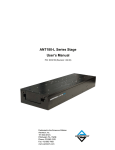
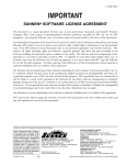
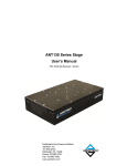
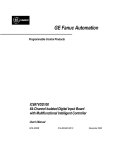
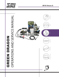
I-SV-495B
New Machine
Inspection and Installation
PROCEDURE
O
P
IM
T
N
RTA
for
SUNNEN® VERTICAL HONING SYSTEM
Model: SV-490 Series
READ THE FOLLOWING INSTRUCTIONS THOROUGHLY AND CAREFULLY BEFORE UNPACKING,
INSPECTING, OR INSTALLING THE SUNNEN® VERTICAL HONING SYSTEM.
“SUNNEN AND THE SUNNEN LOGO ARE REGISTERED TRADEMARKS OF SUNNEN PRODUCTS COMPANY.”
SUNNEN ® PRODUCTS COMPANY • 7910 MANCHESTER ROAD • ST. LOUIS, MO 63143, U.S.A. • PHONE: 314-781-2100
GENERAL INFORMATION
The Sunnen® equipment has been designed and engineered for a wide variety of parts within the capacity and limitation of the equipment. With proper care
and maintenance this equipment will give years of service.
READ THE FOLLOWING INSTRUCTIONS CAREFULLY AND THOROUGHLY BEFORE UNPACKING, INSPECTING, OR INSTALLING THIS EQUIPMENT.
IMPORTANT: Read any supplemental instructions BEFORE installing this equipment. These supplemental instructions give you important information to
assist you with the planning and installation of your Sunnen equipment.
Sunnen Technical Service Department is available to provide telephone assistance for installation, programming, & troubleshooting of your Sunnen
equipment. All support is available during normal business hours, 8:00 AM to 4:30 PM Central Time.
Review all literature provided with your Sunnen equipment. This literature provides valuable information for proper installation, operation, and maintenance
of your equipment. Troubleshooting information can also be found within the Instructions. If you cannot find what you need, call for technical support.
Where applicable, programming information for your Sunnen equipment is also included. Most answers can be found in the literature packaged with your
equipment.
Help us help you. When ordering parts, requesting information, or technical assistance about your equipment, please have the following
information available:
• Have ALL MANUALS on hand. The Customer Services Representative or Technician will refer to it.
• Have Model Number and Serial Number printed on your equipment Specification Nameplate.
• Where Applicable: Have Drive model and all nameplate data. Motor type, brand, and all nameplate data.
For Troubleshooting, additional information may be required:
• Power distribution information (type - delta, wye, power factor correction; other major switching devices used, voltage fluctuations)
• Installation Wiring (separation of power & control wire; wire type/class used, distance between drive and motor, grounding).
• Use of any optional devices/equipment between the Drive & motor (output chokes, etc.).
For fast service on your orders call:
Sunnen Automotive Customer Service toll free at: 1-800-772-2878
Sunnen Industrial Customer Service toll free at: 1-800-325-3670
Customers outside the USA, contact your local authorized Sunnen Distributor.
Additional information available at: http://www.sunnen.com or e-mail: [email protected]
NOTE: Sunnen reserves the right to change or revise specifications and product design in connection with any feature of our products contained herein.
Such changes do not entitle the buyer to corresponding changes, improvements, additions, or replacements for equipment, supplies or accessories
previously sold. Information contained herein is considered to be accurate based on available information at the time of printing. Should any discrepancy of
information arise, Sunnen recommends that user verify the discrepancy with Sunnen before proceeding.
ESD PREVENTION REVIEW
Let's review the basics of a sound static control system and its effective implementation. First, in the three step plan:
1.
Always ground yourself when handling sensitive components or assemblies.
2.
Always use a conductive or shielded container during storage or transportation. These materials create a Faraday
cage which will isolate the contents from static charges.
3.
Open ESD safe containers only at a static safe work station.
At the static safe work station, follow these procedures before beginning any work:
A.
Put on your wrist strap or foot grounding devices.
B.
Check all grounding cords to make sure they are properly connected to ground, ensuring the effective dissipation of static charges.
C.
Make sure that your work surface is clean and clear of unnecessary materials, particularly common plastics.
D.
Anti-static bubble wrap has been included for use at the machine when an ESD safe workstation is not available.
You are now properly grounded and ready to begin work. Following these few simple rules and using a little common sense will go a long
way toward helping you and your company in the battle against the hazards of static electricity. When you are working with ESD sensitive devices, make sure you:
GROUND
ISOLATE
NEUTRALIZE
ii
SUNNEN® LIMITED PRODUCT WARRANTY
Sunnen® Products Company and its subsidiaries (SPC) warrant that all new SPC honing machines, gaging equipment, tooling, and related equipment will
be free of defects in material and/or workmanship for a period of one year from the date of original shipment from SPC.
Upon prompt notification of a defect during the one-year period, SPC will repair, replace, or refund the purchase price, with respect to parts that prove to be
defective (as defined above). Any equipment or tooling which is found to be defective from improper use will be returned at the customer's cost or repaired
(if possible) at customer's request. Customer shall be charged current rates for all such repair.
Prior to returning any SPC product, an authorization (RMA#) and shipping instructions must be obtained from the Customer Service Department or items
sent to SPC will be returned to the customer.
Warranty Limitations and Exclusions This Warranty does not apply to the following:
• Normal maintenance items subject to wear and tear: (belts, fuses, filters, etc).
• Damages resulting from but not limited to:
› Shipment to the customer (for items delivered to customer or customer's agent F.O.B., Shipping Point)
› Incorrect installation including improper lifting, dropping and/or placement
› Incorrect electric power (beyond +/- 10% of rated voltage) including intermittent or random voltage spikes or drops
› Incorrect air supply volume and/or pressure and/or contaminated air supply
› Electromagnetic or radio frequency interference from surrounding equipment (EMI, RFI)
› Storm, lightning, flood or fire damage
› Failure to perform regular maintenance as outlined in SPC manuals
› Improper machine setup or operation causing a crash to occur
› Misapplication of the equipment
› Use of non-SPC machines, tooling, abrasive, fixturing, coolant, repair parts, or filtration
› Incorrect software installation and/or misuse
› Non-authorized customer installed electronics and/or software
› Customer modifications to SPC software
THE LIMITED WARRANTY DESCRIBED HEREIN IS EXPRESSLY IN LIEU OF ALL ANY OTHER WARRANTIES. SPC MAKES NO REPRESENTATION OR WARRANTY OF ANY
OTHER KIND, EXPRESS OR IMPLIED, WHETHER AS TO MERCHANTABILITY, FITNESS FOR A PARTICULAR PURPOSE OR ANY OTHER MATTER. SPC IS NOT
RESPONSIBLE FOR THE IMPROPER USE OF ANY OF ITS PRODUCTS. SPC SHALL NOT BE LIABLE FOR DIRECT, INDIRECT, INCIDENTAL, OR CONSEQUENTIAL
DAMAGES INCLUDING BUT NOT LIMITED TO: LOSS OF USE, REVENUE, OR PROFIT. SPC ASSUMES NO LIABILITY FOR PURCHASED ITEMS PRODUCED BY OTHER
MANUFACTURERS WHO EXTEND SEPARATE WARRANTIES. REGARDLESS OF ANY RIGHTS AFFORDED BY LAW TO BUYER, SPC's LIABILITY, IF ANY, FOR ANY AND
ALL CLAIMS FOR LOSS OR DAMAGES WITH RESPECT TO THE PRODUCTS, AND BUYER'S SOLE AND EXCLUSIVE REMEDY THEREFORE, SHALL IN ALL EVENTS BE
LIMITED IN AMOUNT TO THE PURCHASE PRICE OF THAT PORTION OF THE PRODUCTS WITH RESPECT TO WHICH A VALID CLAIM IS MADE.
Shipping Damages
Except in the case of F.O.B., Buyer's destination shipments, SPC will not be liable for any settlement claims for obvious and/or concealed shipping damages.
The customer bears the responsibility to unpack all shipments immediately and inspect for damage. When obvious and/or concealed damage is found, the
customer must immediately notify the carrier's agent to make an inspection and file a claim. The customer should retain the shipping container and packing
material.
SUNNEN® SOFTWARE LICENSE AGREEMENT
This document is a Legal Agreement between you, as user and licensee (Licensee), and Sunnen® Products Company (SPC) with respect to preprogrammed
software (Software) provided by SPC for use on SPC Equipment. By using the Software, you, as Licensee, agree to become bound by the terms of this
Agreement.
In consideration of payment of the license fee (License Fee) which is part of the price evidenced by your receipt (Receipt), SPC grants to you as Licensee
a non-exclusive right, without right to sub-license, to use the particular copy of the SPC Software licensed hereunder only on the particular equipment sold with
the Software. SPC reserves all rights including rights not otherwise expressly granted, and retain title and ownership to the Software including all subsequent
copies or updates in any media. The Software and all accompanying written materials are covered by copyrights owned by SPC. If supplied on removable
media (floppy disk), you, as Licensee, may copy the Software only for back up purposes; or you may request that SPC copy the Software for you for the
same purposes. All other copying of the Software or of the accompanying written materials is expressly forbidden and is in violation of the Agreement.
The Software and accompanying written materials (including the user's manual, if any) are provided in an "as is" condition without warranty of any kind
including the implied warranties of merchantability and fitness for a particular purpose, even if SPC has been advised of this purpose. SPC specifically does
not warrant that it will be liable as a result of the operation of the Software for any direct, indirect, consequential or accidental damages arising out of the
use of or inability to use such product even if SPC has been advised of the possibility of such use. It is recognized that some states do not allow the exclusion or limitation of liability for consequential or accidental damages and to the extent this is true, the above limitations may not apply.
Any alteration or reverse engineering of the software is expressly forbidden and is in violation of this agreement.
SPC reserves the right to update the software covered by this agreement at any time without prior notice and any such updates are covered by this
agreement.
iii
SAFETY INSTRUCTIONS
READ FIRST
This machine, like any equipment, may be dangerous if used improperly. Please
read all warnings and instructions before attempting to use this machine.
Always disconnect power at main enclosure before servicing machine.1
Always wear eye protection when operating this machine.
NEVER open or remove any machine cover or protective guard with power "ON."
Always disconnect power at main enclosure before servicing this equipment.1
DO NOT attempt any repair or maintenance procedure beyond those described in
this book. Contact your Sunnen® Field Service Engineer or Technical Services
Representative for repairs not covered in these instructions.
Due to the wide variety of machine configurations, all possibilities cannot be
described in these instructions. Instructions for safe use and maintenance of
optional equipment ordered through Sunnen, will be provided through separate
documentation and/or training provided by your Sunnen Field Service Engineer or
Technical Services Representative.
DO NOT attempt to defeat any safety device on this machine or on any of the
optional equipment.
If specially built automation components are added to this system, be sure that
safety is not compromised. If necessary, obtain special enlarged work area safety
system from Sunnen Products Co.
Important information to assist you with
Indicates CE version ONLY.
the unpacking and installation of your
Sunnen Vertical Honing System.
1
DO NOT touch electrical components until main input power has been turned off and CHARGE lamps are
extinguished. WARNING: The capacitors are still charged and can be quite dangerous.
IMPORTANT NOTE
The temperature requirements of the Sunnen® SV490 Vertical Honing Machine have been established as 35 degrees C (95 degrees F). Above this temperature,
an optional cooler will be available to handle temperatures from 35º to 46º C (95º to 115º F). IT IS NOT recommended that the SV Machine be operated at
temperatures above 46º C (115º F). Sunnen Products Company warrants the SV Machine for operating environments up to 35ºC (95º F). For operating
environments of 35º to 46º C (95º to 115º F) the warranty only applies if the optional cooler is installed on the Machine. No warranty coverage is offered for
operating environments above 46º C (115º F).
INTRODUCTION
This Instruction Manual provides information required to install, operate, and maintain Sunnen® Vertical Honing Machine.
When ordering parts for, or requesting information about your Machine, include model and serial numbers, located on Electrical Enclosure of your
Machine.
In this book the
symbol indicates steps or information that are only for CE version of this machine. The CE version is constructed to meet highest level
of safety standards as required by the European Machinery Directive. Required for European market, this CE version is available for any customer. The
regular version of this machine is quite safe for any operator exercising a normal degree of caution associated with machine tool use. The CE version
provides an extra level of protection by minimizing risks of operator carelessness.
The SV410 Vertical Honing Machine is to be used for finishing bores in small workpieces. In finishing bores, this machine can achieve any or all of
following results: fast stock removal, consistent final size, a high degree of cylindrically, fine surface finish. To achieve best results and ensure safe
operation, ONLY Sunnen Tools and Abrasives are to be used in the SV490.
iv
NEW MACHINE
INSPECTION & INSTALLATION PROCEDURE
FOR SUNNEN® VERICAL HONING SYSTEM
GENERAL
1. Move Machine to staging/unpacking area.
Consult this section when unpacking, inspecting,
and installing Sunnen® Vertical Honing Machine
(see Figure 1). Hereafter referred to as the machine.
2. Remove plastic wrap.
TOOLS & MATERIALS
4. Remove all loose components from crate.
The following tools and materials are required for
unpacking and installing of your Machine:
Knife
Hex Wrenches
Hammer
Open End Wrenches
Crow Bar
Cleaning Solvent
Tin Snips
Screwdriver (Std)
Slip Joint Pliers Forklift
5. Check all components against packing list
3. Remove top and sides from packing crate.
6. Inspect Machine and components for dents,
scratches, or damage resulting from improper handling, by carrier. If damage is evident, immediately
file a claim with carrier.
CAUTION
Machine Base may be forked from any side. DO
NOT support weight of machine on bottom of
Electrical Enclosure when lifting or moving.
INSTALLATION
Read the following instructions carefully and
thoroughly before unpacking, inspecting and
installing your Machine. All references to right and
left in these instructions are, unless otherwise noted,
as seen by operator as one looks at Machine or
assembly being described (refer to Figure 1).
7. Remove Bolts securing Machine to Skid.
8. Using a forklift remove machine from skid and
move to desired location and lower into place (see
Figure 2).
While machine is up in the air, screw in Four (4)
Corner Feet and Two (2) Center Feet.
NOTE: When ordering parts for, or requesting
information about your Machine, include Model and
Serial Numbers printed on Nameplate.
NOTE: Machine should be located on a leveled
concrete floor away from heavy traffic. Allow at least
1m (38in.) around enclosure to any adjacent equipment
and walls. Refer to Figure 1-A, Floor Plan Layout.
R
9. Level and stabilize Machine by placing a millwright's
level on ground Table Base (see Figure 3). Machine
needs to leveled both from front to back and left to
right.
LEFT
SV-3
R
60
RIGHT
FRONT
FIGURE 1, Vertical Honing Machine
FIGURE 2, Fork Lift
1
NOTE: Machine does not need to be bolted to floor
but should be set on 1/2" thick steel pads.
JAM NUT
LEVELING
BOLT
• Begin by screwing ALL six (6) Adjustable Feet all
the way into the Table Base (until table base is resting
on the floor).
• Then check to see if any of the feet are not
touching the floor or touching the floor only
loosely. If so, bring foot down to just touch floor.
• Place Level front to back on right side of table and
adjusting Leveling Bolts in each of the right front &
rear feet as required, until table base is within
0,0003 m/m.
• Re-check and adjust any feet that are loose or not
touching, until they just touch the floor.
• Repeat for left side of table.
• Re-check and adjust any feet that are loose or not
touching, until they just touch the floor.
• Move to front of table and check front of table left
to right for level. Adjusting Leveling Bolt in which
ever of the feet is lowest as required, until table
base is within 0,0003 m/m.
• Adjust center Leveling Bolts at front of table until
it just touches the floor.
• Move to rear of table and check rear of table left
to right for level. Adjusting Leveling Bolt in which
ever of the feet is lowest as required, until table
base is within 0,0003 m/m.
SHIM
SHIM
MILLWRIGHT’S
LEVEL
SHIMS
FIGURE 3, Leveling Bolts
CROSS
BRACKET
NOTE: In most cases the lowest foot should be on the
same side in the rear as the one that was just adjusted
on the front of the table.
• Adjust center Leveling Bolts at rear of table until it
just touches the floor.
• Recheck table front to back and left to right.
• Tighten Jam Nuts on all the feet to lock bolts in
place.
• After leveling Table Base using by adjusting the
feet; place shims under table base wherever the base
is not in direct connect with the floor.
FIGURE 4, Shipping Brackets
NOTE: This is very important. If Table Base is not
supported it may bowl when the weight of the fixture
and workpiece are installed.
SCREWS
10. ATTENTION - Remove steel Cross Bracket that
supports machine during shipping (see Figure 4).
11. Adjust Leveling Bolts as required to level
machine.
OPERATOR
CONTROL
STATION
12. Remove Operator Control Station from inside of
Machine and attach to right front of Guarding as
shown (see Figure 5).
13. Remove Hardware securing Wiring Conduit to
rear of Machine and tie Wiring Conduit off to side
of Machine (see Figure 6).
FIGURE 5, Operator Control Station
2
14. Remove back panels from machine for column
installation (see Figure 7). Lay aside for
reinstallation after Column is installed.
Install Column
HANGER
15. Move Column to staging/unpacking area.
16. Remove plastic wrap.
CONDUIT
17. Unbolt Column from Skid (see Figure 8).
18. Run straps thru Lifting Sleeves, provided on
sides of Column (refer to Figure 8).
19. Block lower end of column, to kept bottom from
kicking out as top end of column is lifted.
20. Using an overhead crane: Hook straps and
slowly lift top end of column until top shipping
brackets are free of shipping pallet
FIGURE 6, Wiring Conduit
21. With column now supported by overhead crane;
unbolt top shipping bracket and remove (refer to
Figure 8).
22. Using an overhead crane: Slowly lift top end of
column until column is standing vertical (see Figure 9).
23. With column now supported by overhead crane;
unbolt lower shipping bracket from column (see
Figure 10).
24. Using overhead crane; lift Column and move
into position at rear of machine (see Figure 11).
CAUTION
When position Column Assembly, ensuring assembly
clears Guarding.
FIGURE 7, Back Panels
25. Slowly lower Column Assembly onto Lower
Riser Weldment (see Figure 12).
● Position and align Column Assembly into placed
with holes in Lower Riser Weldment.
● With Column aligned with Lower Riser
Weldment; install using eight (8) Mounting Screws.
BOLTS SECURING
BRACKETS TO
MACHINE
LIFTING
SLEEVE
SHIPPING
BRACKETS
BOLTS SECURING
MACHINE TO SKID
FIGURE 8, Upper Shipping Bracket
FIGURE 9, Lifting Column
3
26. Tighten Mounting Screws (see Figure 13).
MOUNTING
SCREW
27. Remove lifting straps (see Figure 14).
28. Remove lifting brackets from column.
29. Reattach upper end of Cable Carrier to side of
column (see Figure 15).
30. Then reattach Wiring Conduit to rear of
Machine (refer to Figure 5).
31. Install Back Panels and Upper Stainless Panels
(see Figure 16).
COLUMN
32. Remove Red shipping brackets from side walls
and across door opening.
33. If equipped, reinstall Guide Pod Upper Rail
Brackets (see Figure 17).
34. Install conduit hangers and position wiring
conduit in hangers and secure.
RISER
35. Reattach operator console to front of machine
and reroute and secure conduit.
LOWER RISER
WELDMENT
FIGURE 112, Positioning Column on Riser
BOLTS
MOUNTING
SCREW
RISER
SHIPPING
BRACKETS
MOUNTING
SCREW
FIGURE 10, Lower Shipping Bracket
LOWER RISER
WELDMENT
FIGURE 13, Securing Column
FIGURE 14, Lifting Sleeves
FIGURE 11, Position Column
4
CARRIAGE
CABLE
36. Reattached column throat panel to spindle
housing with screws down both sides and across
front (see Figure 18).
CARRIAGE
CABLE END
37. Wipe all protective shipping oil and grease from
Machine. (Clean rust preservative from way bars
and any other bright metal surfaces.)
MOUNTING
LOCATION
38. If applicable: Position optional coolant system on
right side of base.
COLUMN ELECTRICAL CONNECTIONS
All wiring is to be performed by a competent,
Licensed Electrician in accordance with all local,
state, and federal codes and regulations; along with
any special information provided on machine
nameplate or electrical specification plate.
FIGURE 15, Carriage Cable
UPPER
STAINLESS
STEEL PANELS
CAUTION
All wiring is to be performed by a competent,
licensed electrician in accordance with all local, state
and federal codes and regulations. FAILURE TO
COMPLY CAN RESULT IN PERSONAL INJURY
AND DAMAGE TO THE MACHINE.
WARNING
All wiring and electrical equipment service should
be performed by authorized personnel ONLY.
BACK
PANELS
1. Open Door to Column Electrical Enclosure.
2. Remove any packing materials from inside of
enclosure.
FIGURE 16, Back Panels
3. Slide wire leads through side of Enclosure and
secure Wiring Conduit by tightening Lock Ring on
Conduit Connector (see Figure 19).
4. Attach numbered Wire Leads to corresponding
numbered locations inside enclosure.
CAUTION
After installation check positions of Dip Switches
inside Column Enclosure.
UPPER
RAIL
BRACKET
MACHINE ELECTRICAL CONNECTION
All wiring is to be performed by a competent, Licensed
Electrician in accordance with all local, state, and
federal codes and regulations; along with any special
information provided on machine nameplate or
electrical specification plate (see Figure 20).
FIGURE 17, Guide Pod
SCREWS
CAUTION
This machine was wired for 460VAC. If it is to be
run at 400VAC the taps on the control transformer 1T
must be changed. All wiring is to be performed by a
competent, licensed electrician in accordance with
all local, state and federal codes and regulations.
FAILURE TO COMPLY CAN RESULT IN PERSONAL
INJURY AND DAMAGE TO THE MACHINE.
SCREWS
COLUMN
THROAT
PANEL
FIGURE 18, Column Throat Panel
5
WARNING
All wiring and electrical equipment service should
be performed by authorized personnel ONLY.
CAUTION
Door is equipped with lockable Safety Door Latch.
Door should be closed and latched during operation
to prevent accidental interruption of operation from
doors being opened. Door Latch should be LockedOut and Tagged during servicing to prevent machine
from being powered up.
CAUTION
Do not attempt to connect machine if supply voltage is
not within acceptable limits as noted on nameplate or
electrical specification plate. If supply voltage is not
within these limits MACHINE WILL BE DAMAGED.
Verify supply voltage is same as voltage on Machine
Nameplate or Electrical Specifications Plate.
2. Turn Master ON/OFF Switch to OFF position
and open Door. (Door WILL NOT open unless
Master ON/OFF Switch is in OFF position.)
3. Open Door to enclosure.
NOTE: A pre-drilled hole has been provided in
Electrical Enclosure for Electrical Supply Cord (not
supplied). Connect Cord as follows (refer to Figure20).
WARNING
You must use the hole provided. Drilling any new
holes in the electrical enclosure may void the
warranty.
WARNING
Residual Voltage exists for 2-3 minutes afteraster
ON/OFF Switch is turned OFF. Before working
inside Enclosure, wait for all fans to stop running
to allow drives to discharge.
4. Remove hole plug located on top, left side of the
enclosure. Then install an oil tight fitting.
5. Insert Electrical Supply Cord through Oil Tight
Fitting and route to Electrical Disconnect Block.
6. Strip 254 mm (10 in) off cable's outer jacket.
7. Strip 6 mm (1/4 in) of insulation off each wire.
8. Connect Green Wire (GRN) to Terminal PE on
Electrical Disconnect Switch (Earth Ground).
9. Connect other three wires to Disconnect Block
(1DISC) as noted on Block (L1, L2, L3).
1. Unlock Door to Electrical Control Enclosure.
Loosen Safety Latches on door(s) to enclosure,
using a screwdriver.
FIGURE 19, Electrical Connections
6
10. Route and secure Cord inside of Enclosure.
11. Tighten Oil Tight Fitting.
12. Close and secure/lock Door to Enclosure.
13. Route and connect Electrical Supply Cord to
factory main power source.
14. Turn ON Master ON/OFF Switch.
MASTER
ON/OFF
SWITCH
NAMEPLATE
LUBRICATING SYSTEM
The machine is equipped with an automatic grease
lubricating system.
Grease Reservoir is filled at the factory with Sunnen
90123 (Kluberplex #BEM34-132 or its equivalent)
(see Figure 21). System is equipped with a Pressure
Switch, which flashes a warning on the operator
display screen when the level/pressure drops below
minimum requirement.
ELECTRICAL
DISCONNECT
BLOCK
COOLANT SYSTEM (Optional)
The machine comes with a Sump Pump and a small
Reservoir. Because of the numerous application
possibilities the machine is not supplied with a coolant
system, optional Coolant Systems are available.
Placement and system requirements will vary with
coolant system used. Sunnen provides several
optional coolant systems. Check with your local
Sunnen Field Service Engineer or Sunnen Products
Company Technical Services for available systems or
before installing another manufacturer's system.
GRN
SUPPLY
CORD
L2
L1
GND
L3
FIGURE 20, Electrical Connection
IMPORTANT
Operating Instructions and Repair Parts Catalogs for
the optional Coolant Systems are supplied by the
systems manufacturer.
Fill Coolant Reservoir with either Sunnen Industrial
Honing Oil or Sunnen Water-Based Coolant. Refer
to Section 4.
COOLANT SYSTEM CONNECTION
The machine comes with a Sump Pump and a small
Reservoir. Intake and Outlet Hose Barbs are provided for
connecting optional Coolant System (see Figure 22):
CAUTION
Supply coolant pressure should not exceed 20 psi
(0,14 MPa).
FIGURE 21, Lubricating System
MAGNETIC SEPARATOR (Optional)
Like the Coolant System, the machine is not supplied
with a magnetic separator (see Figure 23). If your
application produces large amounts of metal residue, it
is recommended that you employ either or both a
magnetic separator and filter system. Check with your
local Sunnen Field Service Engineer or Sunnen
Products Company Technical Services for available
options or before installing another manufacturer's
system.
FIGURE 22, Coolant System (opt.)
7
SPECIAL FIXTURE (Optional)
Because of the numerous applications possibilities the
machine is not supplied with any fixturing, optional
fixtures are available. Check with your local Sunnen
Field Service Engineer or Sunnen Products Company
Technical Services.
INTAKE
OPERATIONAL CHECK
Read Sections 1, 2 and 3 thoroughly and carefully
before performing the Operational Check.
NOTE: Power up and start machine to check for
proper operation.
MAGNETIC
SEPARATOR
1. Release E-STOP and press POWER ON Button.
NOTE: When machine is powered up it should open
the “Sunnen” software.
FIGURE 23, Magnetic Separator
6. If rotation is incorrect, turn OFF power to
Machine and reverse any two wires (red, white, or
black) of electrical supply cord, where they connect
to Disconnect Block.
2. Once machine is through initializing, press “F1
Setup Menu.”
3. Then press “F2 Install Setup,” and follow
directions on display screen.
7. Operate Machine and check rotation of optional
equipment according to Installation Instruction
package with optional equipment.
4. Once a setup is install; at Main Menu press “F2
Run Menu.”
8. Set up and test all machine functions (refer to
IOM, Section 3).
5. In run settings you can toggle the coolants lines
to check the rotation of the Sump Pump Motor.
(Rotation of Shaft should be as shown on Motor
Cover.)
9. After unpacking and installing Machine, clean
and lubricate (refer to IOM, Section: 4).
8
NEW MACHINE
INSPECTION & INSTALLATION PROCEDURE
CHECKLIST
FOR SUNNEN® MODULAR HONING SYSTEM
MECHANICAL
q 1.
q 2.
q 3.
q 4.
q 5.
q 6.
q 7.
q 8.
q 9.
q 10.
q 11.
q 12.
q 13.
q 14.
ELECTRICAL
q
q
q
q
q
q
q
Move machine to staging area.
Remove shipping carton.
Remove all loose components.
Check components against list.
Inspect Machine and components.
Remove Bolts securing Machine to Skid.
Lift Machine and install Adjustable Feet.
1. Open doors to enclosure.
2. Route cables and connect to enclosure.
3. Attach power cord.
4. Route and connect cord to power source.
5. Visual check cable connectors.
6. Close doors to enclosure.
7. Connect coolant system to power source.
Move machine to desired location.
GENERAL
Level machine.
q
q
q
q
q
Install Column.
Make Electrical connections.
Attach coolant system.
Visual check hoses.
Verify all guards are in place.
9
1. Fill grease lubricating system.
2. Connect coolant system supply hose.
3. Connect coolant system return hose.
4. Fill coolant system reservoir.
5. Perform operational check.
DECLARATION OF CONFORMITY
(CE MACHINES)
E
L
P
T
N
M
E
A
M
S OCU
D
E
C
10
WARNING
An Arc Flash Hazard Exists. Follow safe
work practices and wear appropriate
Personal Protective Equipment. Follow
proper lockout/tagout procedures. Failure
to comply can result in death or injury.
Like any machinery, this equipment may
be dangerous if used improperly. Be sure
to read and follow instructions for
operation of equipment.
11
FRACTION / DECIMAL / MILLIMETER EQUIVALENTS CHART
INCH
FRACTION
DECIMAL
MILLIMETER
INCH
FRACTION
DECIMAL
MILLIMETER
INCH
FRACTION
DECIMAL
MILLIMETER
....
.003937
0,1000
9/32
.281250
7,1438
21/32
.656250
16,6688
....
.007874
0,2000
19/64
.296875
7,5406
....
.669291
17,0000
....
.011811
0,3000
5/16
.312500
7,9375
43/64
.671875
17,0656
1/64
.015625
0,3969
....
.314961
8,0000
11/16
.687500
17,4625
....
.015748
0,4000
21/64
.328125
8,3344
45/64
.703125
17,8594
....
.019685
0,5000
11/32
.343750
8,7313
....
.708661
18,0000
....
.023622
0,6000
....
.354331
9,0000
23/32
.718750
18,2563
....
.027559
0,7000
23/64
.359375
9,1281
47/64
.734375
18,6531
1/32
.031250
0,7938
3/8
.375000
9,5250
....
.748031
19,0000
....
.031496
0,8000
25/64
.390625
9,9219
3/4
.750000
19,0500
....
.035433
0,9000
....
.393701
10,0000
49/64
.765625
19,4469
....
.039370
1,0000
13/32
.406250
10,3188
25/32
.781250
19,8438
3/64
.046875
1,1906
27/64
.421875
10,7156
....
.787402
20,0000
1/16
.062500
1,5875
....
.433071
11,0000
51/64
.796875
20,2406
5/64
.078125
1,9844
7/16
.437500
11,1125
13/16
.812500
20,6375
....
.078740
2,0000
29/64
.453125
11,5094
....
.826772
21,0000
3/32
.093750
2,3813
15/32
.468750
11,9063
53/64
.828125
21,0344
7/64
.109375
2,7781
....
.472441
12,0000
27/32
.843750
21,4313
....
.118110
3,0000
31/64
.484375
12,3031
55/64
.859375
21,8281
1/8
.125000
3,1750
1/2
.500000
12,7000
....
.866142
22,0000
9/64
.140625
3,5719
....
.511811
13,0000
7/8
.875000
22,2250
5/32
.156250
3,9688
33/64
.515625
13,0969
57/64
.890625
22,6219
....
.157480
4,0000
17/32
.531250
13,4938
....
.905512
23,0000
11/64
.171875
4,3656
35/64
.546875
13,8906
29/32
.906250
23,0188
3/16
.187500
4,7625
....
.551181
14,0000
59/64
.921875
23,4156
....
.196850
5,0000
9/16
.562500
14,2875
15/16
.937500
23,8125
13/64
.203125
5,1594
37/64
.578125
14,6844
....
.944882
24,0000
7/32
.218750
5,5563
....
.590551
15,0000
61/64
.953125
24,2094
15/64
.234375
5,9531
19/32
.593750
15,0813
31/32
.968750
24,6063
....
.236220
6,0000
39/64
.609375
15,4781
....
.984252
25,0000
1/4
.250000
6,3500
5/8
.625000
15,8750
63/64
.984375
25,0031
17/64
.265625
6,7469
....
.629921
16,0000
1
1.000000
25,4000
....
.275591
7,0000
41/64
.640625
16,2719
1-1/16
1.062500
26,9880
FORMULAS:
MULTIPLY
INCHES (in)
FEET (ft)
x
x
BY
25.4
0.3048
=
=
TO GET
MILLIMETERS (mm)
METERS (m)
MULTIPLY
MILLIMETERS (mm)
METERS (m)
“SUNNEN® AND THE SUNNEN LOGO ARE REGISTERED TRADEMARKS OF SUNNEN PRODUCTS COMPANY.”
Sunnen® reserves the right to change or
revise specifications and product design
in connection with any feature of our
products contained herein. Such changes
do not entitle the buyer to corresponding
changes, improvements, additions, or
replacements for equipment, supplies or
accessories previously sold. Information
contained herein is considered to be
accurate based on available information
at the time of printing. Should any
discrepancy of information arise, Sunnen
recommends that user verify discrepancy
with Sunnen before proceeding.
PRINTED IN U.S.A.
1205
SUNNEN PRODUCTS COMPANY
7910 Manchester Road, St. Louis, MO 63143 U.S.A.
Phone: 314-781-2100
Fax: 314-781-2268
U.S.A. Toll-Free Sales and Service:1-800-325-3670
International Division Fax: 314-781-6128
http://www.sunnen.com
e-mail: [email protected]
x
x
BY
0.03937
3.281
=
=
TO GET
INCHES (in)
FEET (ft)
SWITZERLAND – SUNNEN AG
Phone: ++ 41 71 649 33 33
Fax: ++ 41 71 649 34 34
www.sunnen.ch
e-mail: [email protected]
ITALY - SUNNEN ITALIA S.R.L.
Phone: 39 02 383 417 1
Fax: 39 02 383 417 50
www.sunnenitalia.com
e-mail: [email protected]
FRANCE – SUNNEN SAS
Phone: +33 01 69 30 0000
Fax: +33 01 69 30 1111
www.sunnen.fr
e-mail: [email protected]
BELGIUM – SUNNEN BENELUX BVBA
Phone: +32 38 80 28 00
Fax: +32 38 44 39 01
www.sunnen.be
e-mail: [email protected]
UK – SUNNEN PRODUCTS LTD.
Phone: ++ 44 1442 39 39 39
Fax: ++ 44 1442 39 12 12
www.sunnen.co.uk
e-mail: [email protected]
POLAND – SUNNEN POLSKA SP. Z O.O.
Phone: +48 22 814 34 29
Fax: +48 22 814 34 28
www.sunnen.pl
e-mail: [email protected]
RUSSIA – SUNNEN RUS
Phone: +7 495 258 43 43
Fax: +7 495 258 91 75
www.sunnen.ru
e-mail: [email protected]
CZECH REPUBLIC – SUNNEN S.R.O.
Phone: +420 383 376 317
Fax: +420 383 376 316
www.sunnen.cz
e-mail: [email protected]
CHINA – SHANGHAI SUNNEN MECHANICAL CO., LTD.
Phone: 86 21 5813 3322
Fax: 86 21 5813 2299
www.sunnensh.com
e-mail: [email protected]
©COPYRIGHT SUNNEN® PRODUCTS COMPANY 2012, ALL RIGHTS RESERVED