1
User’s
Manual
YS1350 Manual Setter
for SV Setting
YS1360 Manual Setter
for MV Setting
Operation Guide
l
tiona
Func ment
nce
Enha
IM 01B08E02-01EN
IM 01B08E02-01EN
1st Edition
Product Registration
Thank you for purchasing YOKOGAWA products.
YOKOGAWA provides registered users with a variety of information and services.
Please allow us to serve you best by completing the product registration form accessible
from our homepage.
http://www.yokogawa.com/ns/reg/
Contents
Foreword ................................................................................................................................................................................. 3
Notice....................................................................................................................................................................................... 3
Trademarks ............................................................................................................................................................................. 3
Authorised Representative in the EEA..................................................................................................................................... 3
Revisions.................................................................................................................................................................................. 3
Safety Precautions .................................................................................................................................................................. 3
Handling Precautions for the Main Unit ................................................................................................................................... 4
Waste Electrical and Electronic Equipment (WEEE), (This directive is only valid in the EU).................................................. 4
Checking the Contents of the Package ................................................................................................................................... 5
Symbols Used in This Manual ................................................................................................................................................. 6
About an Electronic Manual .................................................................................................................................................... 6
Introduction to Functions .....................................................................................................................................7
Part Names..............................................................................................................................................................8
Front Panel Part Names........................................................................................................................................................... 8
Swinging the Front Panel Up and Down ................................................................................................................................. 8
Part Names of the Internal Panel Seen with the Front Panel Swung up................................................................................. 9
YS1350/YS1360 Operating Procedure................................................................................................................11
Basic Operations..................................................................................................................................................12
Overview of Display Switching and Operation Keys.............................................................................................................. 12
Registering a Tag................................................................................................................................................................... 15
Monitoring and Control of Regular Operations (Operation Display)...............................................................16
Monitoring and Operating the LOOP Display......................................................................................................................... 16
Monitoring and Operating the METER Display...................................................................................................................... 18
Monitoring and Operating the TREND Display ..................................................................................................................... 20
Monitoring and Operating the ALARM Display ..................................................................................................................... 22
Switching of Operation Modes............................................................................................................................................... 23
Switching by Keystroke.................................................................................................................................................... 23
Switching in Response to Digital Input ........................................................................................................................... 23
Operating the Tuning Displays............................................................................................................................24
Setting SV1 (YS1350)............................................................................................................................................................ 24
Displaying the Operation Display While the Tuning Display is being Shown ........................................................................ 25
Setting the High and Low Limit Setpoints of MV (YS1360).................................................................................................... 26
Setting Alarms........................................................................................................................................................................ 27
Confirming Input and Output Data......................................................................................................................................... 29
Operating the Engineering Displays..................................................................................................................30
Setting the Scale and Decimal Point Position for Process Variables..................................................................................... 30
Installation and Wiring.........................................................................................................................................32
Installation Location............................................................................................................................................................... 32
Mounting Method .................................................................................................................................................................. 33
Mounting the Instrument Main Unit ................................................................................................................................. 33
External Dimensions/Panel Cutout Dimensions .................................................................................................................... 34
Wiring..................................................................................................................................................................................... 35
Wiring Precautions........................................................................................................................................................... 35
Terminal Diagrams of YS1350......................................................................................................................................... 37
Terminal Diagrams of YS1360......................................................................................................................................... 39
Transmitter Supply Power Wiring.................................................................................................................................... 40
Wiring for Digital Input/Output and FAIL Output.............................................................................................................. 40
IM 01B08E02-01EN
1
Contents
Direct Input Wiring (Optional Code /A0) ...................................................................................................................... 41
Wiring for the Serial Communication Interface (Optional Code /A31) ............................................................................ 42
Wiring for Distributed Control System (DCS-LCS) Communication (Optional Code /A32) ............................................. 43
Wiring for the Ethernet Communication Interface (Optional Code /A34) ........................................................................ 43
Wiring for Power Supply and Grounding......................................................................................................................... 44
Installing the Terminal Cover ................................................................................................................................................. 44
Troubleshooting...................................................................................................................................................45
How to Take Actions if the ALM Lamp or FAIL Lamp Lights up ............................................................................................. 45
Backup Operation in the Event of Instrument Failure ........................................................................................................... 48
Recovery Operations after Power Failures ........................................................................................................................... 49
List of Parameters ...............................................................................................................................................50
<Tuning Parameters> ........................................................................................................................................................... 51
<Engineering Parameters> ................................................................................................................................................... 52
The following are related manuals:
2
YS1350 Manual Setter for SV Setting/YS1360 Manual Setter for MV
Setting
User’s Manual (Electronic version)
Chapter 1 Input/Output and Auxiliary Function
Chapter 2 Display and Security Functions
Chapter 3Adjusting Direct Inputs (Temperature/Resistance/
Frequency)
Chapter 4 Processing during Power Failures
Chapter 5 Maintenance
Chapter 6 Specifications
YSS1000 Setting Software for YS1000 Series/
YS1700 Programmable Function
User’s Manual (Electronic version)
Chapter 1 Overview
Chapter 2 YSS1000 Operation Guide
Chapter 3 User Program Creation Guide
Chapter 4 Operation of Computation and Control Programs
Chapter 5 Basic Usage of Control Modules
Chapter 6 Applied Usage of Control Modules
Chapter 7Operations and Application of Computation Module
(Instructions)
Chapter 8 Using Peer-to-peer Communication
Chapter 9 Maintenance
Chapter 10Sample Program
Chapter 11 Worksheets / Program Sheets / Parameter Sheets
Chapter 12List of Text Program Instructions
YS1000 Series Communication Interface
User’s Manual (Electronic version)
Chapter 1 Overview
Chapter 2 Setting Communication Functions
Chapter 3Description of RS-485 Communication (Optional Code: /A31)
Chapter 4Description of Ethernet Communication (Modbus/TCP)
(Optional Code: /A34)
Chapter 5Description of DCS-LCS Communication (Optional
Code: /A32)
Chapter 6Functions and Application of YS1500/YS1700 D-registers
Chapter 7Functions and Application of YS1310/YS1350/YS1360
D-registers
Appendix ASCII Code Table
YS1000 Series Replacement Manual (Electronic version)
Chapter 1 Overview
Chapter 2 Replacement with YS100-compatible Type
Chapter 3Replacement with YS80 Internal Unit-compatible Type
and EBS, I, EK, or HOMAC-compatible Type
Chapter 4Replacement with YS80-compatible Type
Chapter 5 Replacement with 100 Line-compatible Type
IM 01B08E02-01EN
Foreword
Trademarks
Thank you for purchasing the YS1000 series single-loop controller
(hereinafter referred to as “YS1000”).
This manual describes the basic functions and operation methods of
the YS1350/YS1360. Please read though this user’s manual carefully
before using the product.
Note that the manuals for the YS1350/YS1360 comprise the following
five documents:
●Printed manual
Manual Name
YS1350/YS1360 Operation Guide
Manual Number
IM 01B08E02-01EN
This manual describes the basic operation methods.
Precautions on the Use of the YS1000 Series IM 01B08B02-91EN
This manual is always delivered even if ‘without
manuals’ was selected.
●Electronic manuals
Manual Name
YS1350/YS1360 Operation Guide
Manual Number
IM 01B08E02-01EN
This is identical to the printed manual.
YS1350/YS1360 User’s Manual
YS1000 Series Communication Interface
IM 01B08J02-01EN
User’s Manual
This manual describes how to use YS1000 in Ethernet, serial, and
DCS-LCS communications.
YSS1000 Setting Software/YS1700
IM 01B08K02-02EN
Programmable Function User’s Manual
This manual describes how to use YSS1000 and YS1700’s
programmable function.
YS1000 Series Replacement Manual
IM 01B08H02-01EN
This manual describes the compatibility of installation and wiring
with YS100, YS80, EBS, I, EK, HOMAC, and 100 line.
Precautions on the Use of the YS1000 Series IM 01B08B02-91EN
This manual is always delivered even if ‘without
manuals’ was selected.
User’s manuals for YS1000 are available on the following web site:
www.yokogawa.com/ns/ys/im/
You need Adobe Reader 7.0 or later (but the latest version is
recommended) installed on the computer in order to open and read
the manuals.
The printed versions of the electronic manuals are available for
purchase. Contact your nearest YOKOGAWA dealer for details.
● General Specifications
GS Number
YS1350 Manual Setter for SV Setting/YS1360 GS 01B08E02-01EN
Manual Setter for MV Setting
* The last two characters of the manual number and general specification
number indicate the language in which the manual is written.
Notice
● The contents of this manual are subject to change without
notice as a result of continuing improvements to the instrument’s
performance and functions.
● Every effort has been made to ensure accuracy in the preparation
of this manual. Should any errors or omissions come to your
attention, however, please inform YOKOGAWA Electric’s sales
office or sales representative.
● Under no circumstances may the contents of this manual, in part
or in whole, be transcribed or copied without our permission.
1st Edition : Jun. 2014 YK
All Rights Reserved
Copyright © 2014 Yokogawa Electric Corporation
IM 01B08E02-01EN
Authorised Representative in the EEA
Yokogawa Europe BV. (Address: Euroweg 2, 3825 HD Amersfoort,
The Netherlands) is the Authorised Representative of Yokogawa
Electric Corporation for this Product in the EEA.
Revisions
1st Edition: June 2014
IM 01B08E02-02EN
This manual describes the detailed functions and setting items. It
does not contain the communication functions.
General Specification Name
● Our product names or brand names mentioned in this manual are
the trademarks or registered trademarks of YOKOGAWA Electric
Corporation (hereinafter referred to as YOKOGAWA).
● Microsoft, MS-DOS, Windows, Windows XP, and Windows NT
are either registered trademarks or trademarks of Microsoft
Corporation in the United States and/or other countries.
● Adobe, Acrobat, and Postscript are either registered trademarks
or trademarks of Adobe Systems Incorporated.
● Ethernet is a registered trademark of XEROX Corporation.
● We do not use the TM or ® mark to indicate these trademarks or
registered trademarks in this user's manual.
● All other product names mentioned in this user's manual
are trademarks or registered trademarks of their respective
companies.
Safety Precautions
The following contents are for the suffix codes "-0", and "-2."
This instrument is a product of Installation Category II, of IEC/
EN61010-1 Safety Standards and Class A (use in commercial and
industrial areas) of EN61326-1 (EMC Standards) (use a ferrite core
and an arrester to comply with the standards).
CAUTION
This instrument is a class A product (use in commercial and
industrial areas). In a domestic environment this product may
cause radio interference in which case the user needs to take
adequate measures.
The instrument is a product rated Measurement Category O (other).
* Measurement Category O (other)
This category applies to electric equipment that measures a
circuit connected to a low-voltage facility and receives power from
stationary equipment such as electric switchboards.
To use the instrument properly and safely, observe the safety precautions
described in this user’s manual when operating it. Use of the instrument
in a manner not prescribed herein may compromise protection features
inherent in the device. We assume no liability for or warranty on a fault
caused by users’ failure to observe these instructions.
This instrument is designed to be used within the scope of
Measurement Category O (other) and is dedicated for indoor use.
This instrument is an FM Non-incendive or CSA Non-incendive
Standard certified product. (To be approved)
FM Standards FM3611
Locations: C
lass I, Division 2, Groups A, B, C, and D
Class I, Zone 2, Groups II C
Temperature code: T4
CSA nonincendive C22.2 No. 213-M1987
Locations: Class I, Division 2, Groups A, B, C, and D
Temperature Code T4
Notes on the User’s Manual
• This user’s manual should be readily accessible to the end users
so it can be referred to easily. It should be kept in a safe place.
• Read the information contained in this manual thoroughly before
operating the product.
• The purpose of this user's manual is not to warrant that the
product is well suited to any particular purpose, but rather to
describe the functional details of the product.
3
Safety, Protection, and Modification of the Product
The following symbols are used in the product and user’s manuals to
indicate safety precautions:
“Handle with Care” (This symbol is attached to the part(s)
of the product to indicate that the user’s manual should be
referred to in order to protect the operator and the
instrument from harm.)
Protective grounding terminal
Functional grounding terminal (Do not use this terminal as
a protective grounding terminal.)
Alternating current
Direct current
• In order to protect the system controlled by this product and the
product itself, and to ensure safe operation, observe the safety
precautions described in this user’s manual. Use of the instrument
in a manner not prescribed herein may compromise the product's
functions and the protection features inherent in the device.
We assume no liability for safety, or responsibility for the product's
quality, performance or functionality should users fail to observe
these instructions when operating the product.
• Installation of protection and/or safety circuits with respect to a
lightning protector; protective equipment for the system controlled
by the product and the product itself; foolproof or failsafe design
of a process or line using the system controlled by the product
or the product itself; and/or the design and installation of other
protective and safety circuits are to be appropriately implemented
as the customer deems necessary.
• Be sure to use the spare parts approved by YOKOGAWA when
replacing parts or consumables.
• This product is not designed or manufactured to be used in critical
applications that directly affect or threaten human lives. Such
applications include nuclear power equipment, devices using
radioactivity, railway facilities, aviation equipment, air navigation
facilities, aviation facilities, and medical equipment. If so used,
it is the user’s responsibility to include in the system additional
equipment and devices that ensure personnel safety.
• Modification of the product is strictly prohibited.
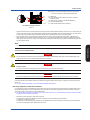
WARNING
● Power Supply
Ensure that the instrument’s supply voltage matches the voltage of
the power supply before turning ON the power.
● Protective Grounding
To prevent electric shock, always confirm that protective grounding is
connected before turning ON the instrument’s power supply.
● Necessity of Protective Grounding
Do not cut off the internal or external protective grounding wire or
disconnect the wiring of the protective grounding terminal. Doing so
renders the protective functions of the instrument invalid and poses a
potential shock hazard.
● Defects in Protective Functions
If protective functions such as grounding are suspected to be
defective, do not operate the instrument. Ensure that all protective
functions are in working order before operating the instrument.
● Do Not Use in an Explosive Atmosphere
Do not operate the instrument in locations with combustible
or explosive gases or steam. Operation in such environments
constitutes an extreme safety hazard. Use of the instrument in
environments with high concentrations of corrosive gas (H2S, SOx,
etc.) for extended periods of time may cause a failure.
● Do Not Remove Internal Unit
The internal unit should not be removed by anyone other than
YOKOGAWA's service personnel. There are dangerous high voltage
parts inside.
4
● External Connection
Ensure that protective grounding is connected before connecting the
instrument to the device under measurement or to an external control
circuit.
● Damage to the Protective Construction
Operation of the instrument in a manner not specified in this user’s
manual may damage its protective construction.
Warning and Disclaimer
• YOKOGAWA makes no warranties regarding the product except
those stated in the WARRANTY that is provided separately.
• The product is provided on an "as is" basis. YOKOGAWA
assumes no liability to any person or entity for any loss or
damage, direct or indirect, arising from the use of the product or
from any unpredictable defect of the product.
Notes on Software
• YOKOGAWA makes no warranties, either expressed or implied,
with respect to the software’s merchantability or suitability for
any particular purpose, except as specified in the terms of the
separately provided warranty.
• This software may be used on one specific machine only.
• To use the software on another machine, the software must be
purchased again separately.
• It is strictly prohibited to reproduce the product except for backup
purposes.
• Store the software CD-ROM (the original medium) in a safe place.
• All reverse-engineering operations, such as reverse compilation
or the reverse assembly of the product are strictly prohibited.
• No part of the product’s software may be transferred, converted,
or sublet for use by any third party, without prior written consent
from YOKOGAWA.
Handling Precautions for the Main Unit
• The instrument comprises many plastic components. To clean it,
wipe it with a soft, dry cloth. Do not use organic solvents such as
benzene or thinner for cleaning, as discoloration or deformation
may result.
• Keep electrically charged objects away from the signal terminals.
Not doing so may cause the instrument to fail.
• Do not apply volatile chemicals to the display area, operation
keys, etc. Do not leave the instrument in contact with rubber or
PVC products for extended periods. Doing so may result in failure.
• If the equipment emits smoke or abnormal smells or makes
unusual noises, turn OFF the instrument’s power switch
immediately and unplug the device. In such an event, contact
your sales representative.
Waste Electrical and Electronic Equipment (WEEE),
(This directive is only valid in the EU)
Foreword
This is an explanation of how to dispose of this product based on
Waste Electrical and Electronic Equipment (WEEE). This directive is
only valid in the EU.
Marking
This product complies with the WEEE Directive marking
requirement.
This marking indicates that you must not discard this
electrical/electronic product in domestic household waste.
Product Category
With reference to the equipment types in the WEEE directive Annex 1,
this product is classified as a “Monitoring and Control instrumentation”
product.
Do not dispose in domestic household waste.
When disposing products in the EU, contact your local Yokogawa
Europe B. V. office.
IM 01B08E02-01EN
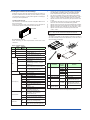
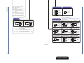
Checking the Contents of the Package
Unpack the box and check the contents before using the product. If
the product is different from that which you have ordered, if any parts
or accessories are missing, or if the product appears to be damaged,
contact your sales representative.
This type can be connected to the YS80 housing (model SHUP).
(The EK/HOMAC-compatible housing (SHUP-420) and EBS/I
series-compatible housing (SHUP-100) are sold separately.)
The 100 line-compatible housing (model YS006) is sold separately.
Direct input options can be combined only with suffix codes “-2,”
“-4,” or “-5.” Selection of multiple options is not possible.
Optional code /DF can be combined only with optional code /A02
or /A03.
A combination with suffix code “-3” is not possible. Optional
codes /A31 and /A32 cannot be simultaneously specified.
Optional codes /A31 and /A32 cannot be simultaneously specified.
Optional codes /A34 can be specified only for suffix codes “-0”.
Optional code /FM can be combined only with suffix codes “-0”.
Optional code /CSA can be combined only with suffix codes
“-0,” “-2”.
*1
*2
*3
*4
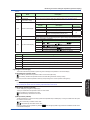
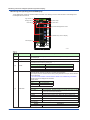
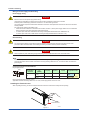
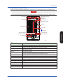
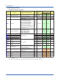
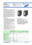
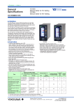
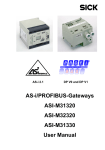
YS1350/YS1360 Main Unit
The YS1350 and YS1360 main units have nameplates affixed to the
tops of the terminals.
Check the model and suffix codes inscribed on the nameplate to
confirm that the product received is that which was ordered.
Nameplate
*5
*6
*7
*8
*9
For the installation and wiring of YS1350/YS1360-2, -3,
-4, or -5, see the YS1000 Series Replacement Manual.
0001E.ai
No. (Instrument number)
When contacting your sales representative, inform them of this
number too.
1
2
3
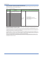
Model and Suffix Codes
Model
Suffix
Code
Optional
Code
Remarks
Manual Setter for SV Setting
YS1360
Manual Setter for MV Setting
5
6
Basic type
0
0
Compatible type for YS100 (with
YS100 case)
Compatible type for YS80 internal unit/
compatible type for EBS, I, EK, and
HOMAC (*1)
Compatible type for YS80 (compatible
size for YS80 with YS100 terminal)
Compatible type for pneumatic 100
line (with YS100 terminal) (*2)
100 V AC, 24 V DC common power
1
220 V AC power
2
3
4
5
Power supply
Direct input (*3)
/A01
mV input
/A02
Thermocouple input
/A03
RTD input
/A04
Potentiometer input
/A05
Isolator
/A06
Two-wire transmitter input (isolated)
/A07
/A08
/DF
/A31
Communication
/A32
/A34
/FM
Certification
/CSA
IM 01B08E02-01EN
er
-2
oll
YS1350: Always “-1”
YS1360: With hard manual unit
YS1360 only: Without hard manual unit
-1
Type
4
tr
on
C le
ng ab
ati m er
ll
dic am o
In gr ntr e
o
00 Pr Co uid
15
S 00 ng G
Y 7 ti n
Y S1 ica tio
Y d ra
In pe
O
YS1350
Use
TA
G
TA NO
G .
TA NO
G .
TA NO
G .
NO
.
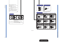
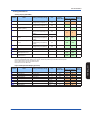
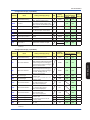
Accessories
The product is provided with the following accessories according to
the model and suffix codes (see the table below). Check that none of
them are missing or damaged.
Two-wire transmitter input (nonisolated)
Frequency input
Direct input with Fahrenheit
temperature function (*4)
RS-485 communication (PClink, Modbus, and YS protocol
communication) (*5)
DCS-LCS communication (*6)
0002E.ai
No.
Item Name
Metal clamps
1
2
Tag plate seals
3
Range entry seals
4
RJC sensor
Part
Number/
Model
Q’
ty
Remarks
For YS13x0-0
L4041RA
2
E9760RJ
2
E9760RN
2
E9760RJ
1
E9760RP
1
L4041UA
6
*1:
YS1350/YS1360
Operation Guide
4
50 × 3.5 mm
34 × 2 mm
Supplied with products with
optional code /A02. (*1)
For direct input cable
(Supplied with products
with optional code /A0.)
This user’s manual, A4 size
L3501RA
1
A1179MN
1
–
For YS13x0-4
4
Ferrite core
5
For YS13x0-2
1
For the RJC mounting, see the chapter “Installation and Wiring” in
this manual or the YS1000 Series Replacement Manual.
Ethernet communication (Modbus/
TCP) (*7)
FM nonincendive approved (FM Class
I, Div 2) (*8) (To be approved)
CSA nonincendive approved (CSA
Class I, Div 2) (*9) (To be approved)
5
Accessories (sold separately)
The following lists accessories that are sold separately. When
ordered, check that none of them are missing or damaged. To inquire
about the accessories or about how to place an order, contact your
sales representative.
No.
Item Name
Sales
Unit
Model
1
120 Ω terminating
resistor (*1)
YS020
1
2
250 Ω shunt resistor YS021
1
*1
Remarks
For RS-485
communication
For a built-in 24 V
transmitter power
supply
The instrument has a built-in terminating resistor, which can be
selected for use by setting the relevant parameter. If a terminating
resistor is used in another device at the termination of the same
communication system, an external terminating resistor needs to
be provided to match the terminating resistance of the YS1000’s
built-in terminating resistor.
Symbols Used in This Manual
This symbol is used on the instrument. It indicates the possibility of
injury to the user or damage to the instrument, and signifies that the
user must refer to the user’s manual for special instructions. The
same symbol is used in the user’s manual on pages that the user
needs to refer to, together with the term “WARNING” or “CAUTION.”
WARNING
Calls attention to actions or conditions that could cause serious or
fatal injury to the user, and indicates precautions that should be taken
to prevent such occurrences.
CAUTION
Calls attention to actions or conditions that could cause injury to
the user or damage to the instrument or property and indicates
precautions that should be taken to prevent such occurrences.
Note
Identifies important information required to operate the instrument.
Indicates related operations or explanations for the user’s reference.
[
]
Indicates a character string displayed on the display.
Setting Display
Indicates a setting display and describes the keystrokes required to
display the relevant setting display.
Perform the operations in chronological order. This section describes
the procedure under the assumption that these steps are being
taken for the first time. There are cases where not all of the steps are
required, depending on the required operation.
Setting Details
Provides the descriptions of settings.
Description
Describes restrictions, etc. regarding a relevant operation.
About an Electronic Manual
User’s manuals for YS1000 are available on the following web site:
www.yokogawa.com/ns/ys/im/
You need Adobe Reader 7.0 or later (but the latest version is
recommended) installed on the computer in order to open and read
the manuals.
6
IM 01B08E02-01EN
Introduction to Functions
Introduction to Functions
YS1350 is a manual setter for SV setting that manually outputs a setpoint signal to a controller.
YS1360 is a manual setter for MV setting that manually outputs a manipulation signal to a final control element.
Features
• Color LCD display
The monitoring and operation display is provided in color, and input and output values, various constants, and incorporated
functions can be set freely using key switches on the front panel. The monitoring displays include LOOP Display, TREND
Display, ALARM Display, and METER Display which provides information in much the same way as analog meters.
• Failsafe function
Two CPUs are configured to provide manual operations and displays even if one of the CPUs becomes faulty. Moreover, because the instrument incorporates a hard manual circuit independent of the digital circuit, it can continue to generate manipulated output variables even if the digital circuit that includes the CPUs fails.
• AC/DC-common power supply with wide operating voltage range.
The instrument can be powered by either AC (100 V AC) or DC (24 V DC).
• The front panel is dust- and water-proof (conforming to IP54).
• Abundant communication functions
The instrument can incorporate Ethernet (Modbus/TCP) communication, serial communication (Modbus, PC-link, and YS
protocol), and DCS-LCS communication.
Definition of Terms
•
•
•
•
•
PV: Process variable input from process
SV: Setpoint regarded as a control target
MV: Manipulated variable for operating control elements such as valves.
M mode: Mode in which internal setpoints or manipulated output variables are operated manually.
C mode: Mode in which external setpoints (YS1350) or manipulated output variables (YS1360) are output.
IM 01B08E02-01EN
7
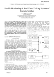
Part Names
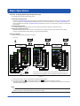
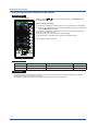
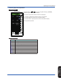
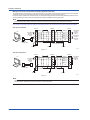
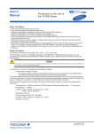
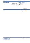
Front Panel Part Names
(10)
(10)
(2)
(2)
(3)
(3)
(4)
(1)
(4)
(1)
(5)
(6)
(9)
(9)
(7)
(7)
(8)
(8)
(5)
(6)
0201E.ai
Figure 2.1
YS1350
Color LCD display: 120 × 320 dots
FAIL lamp (LED: red)
ALM lamp (LED: yellow)
C mode key, M mode key, and LED indicators
(C: green, M: yellow)
(5) SV increase key
(6) SV decrease key
(7) Page key
(8) SHIFT key
(9) Software-key operation Key
(10) TAG label (recommended position to attach label)
(1)
(2)
(3)
(4)
YS1360
Color LCD display: 120 × 320 dots
FAIL lamp (LED: red)
ALM lamp (LED: yellow)
C mode key, M mode key, and LED indicators
(C: green, M: yellow)
(5) MV decrease key
(6) MV increase key
(7) Page key
(8) Fast-change key/SHIFT key
(9) Software-key operation Key
(10) TAG label (recommended position to attach label)
(1)
(2)
(3)
(4)
► For the functions of each part: see “Monitoring and Control of Regular Operations (Operation Display)” in this manual.
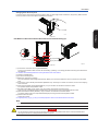
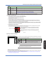
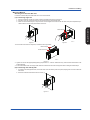
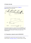
Swinging the Front Panel Up and Down
Swinging up the front panel
1. Press upwards in the center of the bottom of the front panel. You can draw the front panel toward you until you feel a slight
resistance and the movement of the front panel will stop.
(You can swing up the front panel more smoothly if hold the top and bottom of the front panel.)
2. Swing the front panel up and out from that position.
Front Panel
Figure 2.3
Figure 2.2
8
0203E.ai
0202E.ai
IM 01B08E02-01EN
Part Names
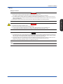
Swinging down the front panel
Push down on the center of the top of the front panel. When you feel a slight sense of resistance, stop pushing. Slide it forward
from that position. It will click into place, indicating that it is locked.
Part Names
0204E.ai
Figure 2.4
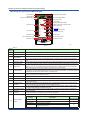
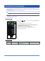
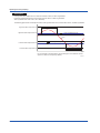
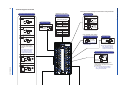
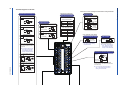
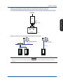
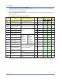
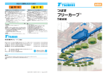
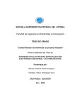
Part Names of the Internal Panel Seen with the Front Panel Swung up
(5)
(3)
(2)
(only for YS1360) (7)
(5)
(4)
(9)
(1)
(8) (only for YS1360)
(6) (only for YS1360)
Figure 2.5
0205E.ai
(1)Connector for connection to a PC (PROGRAMMER)
This is a communication cable connector for downloading, uploading, or monitoring parameters set using the YSS1000 Setting Software.
► YSS1000: YSS1000 Setting Software/YS1700 Programmable Function User’s Manual
(2)Internal unit release lever
(3)An internal unit fixing screw
(4)Metal lever: Used only for YS1360.
Touch the metal lever to discharge static electricity. Before you connect the cable to the YS110 connector, touch the metal
lever.
(5)Connector for YS110 standby manual station (MANUAL STA) : Used only for YS1360. For YS1350, do not connect anything
to this connector.
(6)Hard manual operation wheel (HARD MANUAL) : Only for YS1360. YS1350 does not have this wheel.
An operation wheel to manipulate an output
(7)MV balance lamp (BAL) (Color: green) : Only for YS1360. YS1350 does not have this lamp.
Lights up when a manipulated output variable and the hard manual unit’s output value agree with each other.
(8)Hard manual selector switch (ON/OFF) : Only for YS1360. YS1350 does not have this switch.
The switch used to switch to a manipulated variable (MV) set using the hard manual operation wheel.
(9)LED and switch for repair
Contact us for repair.
► Regarding items (4), (5), (6), (7), and (8): see “Backup Operation in the Event of Instrument Failure” in this manual.
Note
For products with suffix code -2xx, there are no hard manual unit-related parts ( (6), (7), and (8)).
WARNING
Do not remove the internal unit from the instrument case. Contact YOKOGAWA’s sales office or sales representative when
removing the internal unit, as safety standard inspection is required.
IM 01B08E02-01EN
9
Part Names
WARNING
Explosion hazard.
Do not remove or insert the internal unit in explosive atmospheres.
CAUTION
Products with optional code /FM or /CSA cannot satisfy the explosion protection standards if the internal unit is removed.
10
IM 01B08E02-01EN
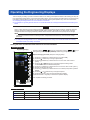
YS1350/YS1360 Operating Procedure
When using the instrument for the first time, proceed according to the following sequence:
YS1350/YS1360
Unpack the instrument and
check the specifications
► Checking the Contents of the Package (p.5)
Part Names
Installation
► Installation and Wiring (p.32)
Turn ON power supply
► Operating the Engineering Displays
(from p.30)
Start tuning/operation
Tuning/operations can be set using
the YSS1000 Setting Software.
► YSS1000 Setting Software/YS1700 Programmable
Function User’s Manual
► Operating the Tuning Displays (from p.24)
Regular operation
► Monitoring and Control of Regular Operations (from p.16)
Figure 3.1
IM 01B08E02-01EN
0301E.ai
11
YS1350/YS1360 Operating
Procedure
Set up engineering constants
Basic Operations
Overview of Display Switching and Operation Keys
The YS1000 has the following three display groups:
(1)Operation Display Group
Includes the LOOP Display (YS1350) used to switch the operation mode during operation or set SV, LOOP Display (YS1360)
used to manipulate MV, TREND Display that displays trends of PV and SV (YS1350) or MV (YS1360), ALARM Display that
displays detailed alarm information, and METER Display that displays PV and SV (YS1350) or MV (YS1360) on a meter scale
using a pointer.
(2)Tuning Display Group
Includes the Display and Setting Display for tuning parameters and Monitor Display for input/output signals.
Includes the display used to set functions as a manual setter for SV setting (YS1350) or a manual setter for MV setting
(YS1360), Input Specification Setting Display, and Password Setting Display.
(3)Engineering Display Group
Selecting a Display
The flow of display selecting operations is as follows:
Power ON
Operation Display
group
SHIFT
SHIFT
SHIFT
+
+
+
Tuning Display
group
Engineering Display
group
C
For operations of the Tuning Display and Engineering Display groups, see
“Operating the Tuning Displays” and “Operating the Engineering Displays.”
Figure 4.1
1.
2.
0401E.ai
When the instrument’s power is turned ON, the Operation Display appears.
Each time the Page key ( ) is pressed with the SHIFT key ( SHIFT ) held down, the display is switched.
The display changes in the order of Operation Display, Tuning Menu Display, and Engineering Menu Display, after which the
Operation Display reappears.
Note
Operation of the SHIFT key + Page key (a two key keystroke) implies that you should press the Page key with the SHIFT key
held down. Doing so in the opposite order does not switch the display.
12
IM 01B08E02-01EN
Basic Operations
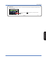
Software keys
Software keys are keys displayed on the LCD. The functions of the software keys are assigned to the operation keys on
the right of the display.
In the figure at the left, the ↑ (UP) software key corresponds with the
mode key.
Figure 4.2
0402E.ai
Basic Operations
IM 01B08E02-01EN
13
Basic Operations
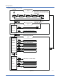
Display Switching (factory setting)
Power ON
Operation Display
group
LOOP1
Display
METER1
Display
+
Tuning Menu
Display
TREND1
Display
The turning ON/OFF of each Operation
Display and the initial Operation Display
which appears when the power is turned
on can be set.
TREND3
Display
Tuning Display
group
ALARM
Display
To the LOOP 1, TREND 1,
or METER 1 Display
OPE
SETTING
Setting Display
[SETTING ]
I/O DATA
Input and Output Data Display
[I/O DATA ]
+
Engineering
Menu Display 1
Engineering Diplay
group
CONFIG1
[CONFIG1 ]
Function Setting Display 1
CONFIG2
[CONFIG2 ]
Function Setting Display 2
CONFIG3
[CONFIG3 ]
Function Setting Dispaly 3
SC MAINT
[SC MAINT ]
Input Specification Setting Display
+
PASSWORD
[PASSWORD ]
Engineering
Menu Display 2
Passward Setting Display
DISPLAY
[DISPLAY ]
Setting Display for Operation Display
LCD
[LCD
]
LCD Setting Display
COMM
[COMM
]
Communication Setting Display
LCD MAINT
[LCD MAINT]
LCD Maintenance Display
Figure 4.3
14
0403E.ai
IM 01B08E02-01EN
Basic Operations
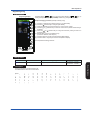
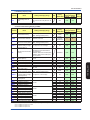
Registering a Tag
Setting Display
Engineering Display
Operation Display > SHIFT +
keys (to the Tuning Menu Display) > SHIFT +
keys (to
the Engineering Menu Display) > [CONFIG2] software key (Configuration Display 2)
Setpoint changing procedure (example of setting a tag):
(1)
(2)
(3)
(4)
(5)
(6)
(7)
(8)
Press the [↓] software key to select and zoom in on [SET INHB].
Press the [ ] software key to change to [SET ENBL].
Press the [↓] software key to select and zoom in on tag number 1 [TAG1].
Press the [↓] or [↑] software key to move the cursor over the position where the tag is
registered.
Press the [ ] or [ ] software key to change the character (setting is made on a
character basis).
Repeat steps (4) and (5) to register the tag.
(To erase a character, enter a space.)
Press the Page key to return to the Engineering Menu Display.
Press the SHIFT + Page keys to return to the Operation Display.
This completes the setting procedure.
0404E.ai
Setting Details
Parameters
Names
TAG1
Setting Range
Tag number
Factory Default
For YS1350: ---YS1350--For YS1360: ---YS1360---
12 digits of alphanumeric characters
Basic Operations
Description
The tag is displayed in the top line of the LCD.
The settable ASCII codes are as shown below:
Space
.
>
M
¥
k
z
IM 01B08E02-01EN
/
?
N
]
l
{
!
0
@
O
^
m
¦
“
1
A
P
_
n
}
#
2
B
Q
`
o
~
$
3
C
R
a
p
%
4
D
S
b
q
&
5
E
T
c
r
’
6
F
U
d
s
(
7
G
V
e
t
)
9
H
W
f
u
*
:
I
X
g
v
+
;
J
Y
h
w
,
<
K
Z
i
x
=
L
[
j
y
15
Monitoring and Control of Regular Operations
(Operation Display)
Monitoring and Operating the LOOP Display
(7) SV digital display
Tag number (1)
(18) Operation status display
Display title (2)
(14) Engineering units
PV overflow (6)
(16) 100% value of scale
PV digital display (3)
PH pointer (5)
(20) Key LOCK status display
MV digital display (9)
(15) PV bar scale
(8) SV pointer
Alarm generation display,
(17)
control status display
(4) PV bar
PL pointer (5)
Cascade input value (19)
(16) 0% value of scale
PV underflow (6)
ML pointer (11)
(11) MH pointer
MV valve direction (13)
(13) MV valve direction
(12) MV overflow
MV underflow (12)
MV bar, MV scale (10)
(19) Cascade input value
0501E.ai
Figure 5.1
Table 5.1
No. in
Figure
Description
(1)
Tag number
A tag number combining alphanumeric characters and symbols having a maximum of 12 digits
is displayed.
(2)
Display title
The title of the display being shown is indicated.
(3)
(4)
(5)
(6)
(7)
(8)
(9)
(10)
(11)
(12)
(13)
16
Name
A PV value is displayed in engineering units in a digital value of five significant digits (seven
digits including a sign and decimal point).
A PV value is displayed in a bar. The bar display is in 200 dots at full scale (100%) and
PV bar
increases/decreases on a dot (0.5%) basis.
PH values (high limit alarm setpoints for PV) and PL values (low limit alarm setpoints for PV) are indicated
PH, PL pointers
with triangular pointers.
PV underflow and
A PV underflow is displayed if a PV value is below 0%, while a PV overflow is displayed if it
PV overflow
exceeds 100%.
SV digital display
An SV value is displayed in engineering units in a digital value of five significant digits (seven
(YS1350)
digits including a sign and decimal point).
SV pointer
SV values are indicated with triangular pointers. The pointer display moves up and down with a
(YS1350)
resolution of 0.5%.
MV digital display
An MV value is displayed in a digital value of four significant digits (six digits including a sign
(YS1360)
and decimal point, with the number of decimal places fixed to one digit) in a % display.
MV bar
An MV value is displayed in a bar. The bar display is in 80 dots (100%) at full scale, divided into
MV scale
20 blocks (5%) for display. It increases/decreases on a dot (1.25%) basis. A scale divided into
(YS1360)
10 (10% segments) is also displayed.
MH and ML pointers MH values (high limit setpoints for MV) and ML values (low limit setpoints of MV) are indicated
(YS1360)
with triangular pointers.
MV underflow and
An MV underflow is displayed if an MV value is below 0%, while an MV overflow is displayed if it
MV overflow
exceeds 100%.
(YS1360)
MV valve direction
MV valve direction is displayed as [C] (closed) or [O] (open).
(YS1360)
PV digital display
(14)
Engineering unit
Engineering units (UNIT) are displayed in a maximum of seven digits.
(15)
PV bar scale
The PV bar scale is displayed divided into a maximum of 10 segments (10% segments).
IM 01B08E02-01EN
Monitoring and Control of Regular Operations (Operation Display)
Table 5.2
No. in
Figure
Name
Description
0% value of scale, 100% 0% value of scale (SCL) and 100% value of scale (SCH) are displayed in engineering units in
value of scale
a digital value of five significant digits (seven digits including a sign and decimal point).
Alarm generation display, Alarm and control statuses are displayed in abbreviations. See Tables 5.3.
Control status display
The controller operation status is displayed.
(16)
(17)
Display
(18)
Operation status display
(19)
Cascade input value
[POWER DOWN]
[H.MAN]
(No indication)
[STOP]
When the instrument is used in the C mode, a cascade input value is displayed in engineering
units in a digital value of five significant digits (seven digits including a sign and decimal point).
The key LOCK status is displayed.
Display
[ALLK]
Key LOCK status display
(20)
Display
Priority Order
Power down is being detected.
(1)
Hard manual selector switch has been activated.
(2)
The instrument is operating.
(3)
Operation stopped (such as while setting a
function on the Engineering Display, etc.)
Description
Description
, and
keys, SV increase and decrease (
,
) keys, and MV
increase and decrease (
,
) keys are disabled.
[MDLK]
, and
keys are disabled.
[SVLK]
SV increase and decrease (
[MVLK]
MV increase and decrease (
,
) keys are disabled.
,
) keys are disabled.
Table 5.3 Meaning of Display Abbreviations
Symbol
Meaning
SYS-ALM
A system alarm occurred.
ALARM-1
A loop 1 process alarm occurred.
CAS
Remote operation being conducted in response to external setpoint input
DDC
Remote operation being conducted in response to SV (YS1350)/MV (YS1360) from a high-level device
BUM
Transition to backup manual status
EXT-MAN Transition to manual control in response to external digital input
Operating the LOOP Display
This section describes keystrokes for performing various settings and operations on the LOOP Display.
(1)Switching the operation mode
M mode key: Switches the operation mode to manual control (M mode).
C mode key: Switches the operation mode to cascade setting automatic control (C mode).
Moreover, the LED inside the operation mode key corresponding to the current operation mode lights up.
Monitoring and Control of
Regular Operations
Note
If a cascade input signal is −6.3% or less or 106.3% or more, the operation mode cannot be switched to C mode.
► For switching the operation mode: see “Switching of Operation Modes” in this manual.
(2)SV setting operation (YS1350)
The SV setting key changes the setpoint (SV).
This key is enabled when the operation mode is in the M mode.
SV increase key: Increases an SV value.
SV decrease key: Decreases an SV value.
(3)MV operation (YS1360)
The MV operation key is used to manually operate a manipulated output variable (MV). This key is enabled when the operation mode is in the M mode.
MV increase key: Increases an MV value.
MV decrease key: Decreases an MV value.
Moreover, pressing an MV operation key with the
increase/decrease speed.
IM 01B08E02-01EN
SHIFT
(fast-change key/SHIFT key) held down accelerates the MV-value
17
Monitoring and Control of Regular Operations (Operation Display)
Monitoring and Operating the METER Display
(16) Operation stauts display
Tag number (1)
Display title (2)
PV,SV,MV digital display (3)
(18) Control status display
(4) PV meter scale
(6) Scale factor
(17) Key LOCK status display
PH pointer (11)
(5) Main scale marks, subscale marks
(7) Numerical scale
(8) PV pointer
(9) SV pointer
PL pointer (11)
(10) Engineering units
ML pointer (14)
(14) MH pointer
MV valve direction (15)
(15) MV valve direction
MV pointer (13)
(12) MV meter scale
0502E.ai
Figure 5.2
Table 5.4
No. in
Figure
(1)
Name
Description
Tag number
As on the LOOP Display, a tag number appears here.
(2)
Display title
The title of the display being shown is indicated.
(3)
PV, SV, and MV
digital display
PV, SV (YS1350), and MV (YS1360) digital values are displayed here.
(4)
PV meter scale
(5)
Main scale marks,
subscale marks
(6)
Scale factor
(7)
Numerical scale
(8)
PV pointer
(9)
SV pointer (YS1350)
An SV value is indicated with a pointer. The pointer display moves up and down with a resolution of 0.5%.
(10)
Engineering units
Engineering units (UNIT) are displayed in a maximum of seven digits.
(11)
(12)
(13)
(14)
(15)
The PV meter scale displays main scal and subscale marks, a numerical scale, a scale factor, and engineering
units.
The main scale marks and subscale marks are determined by setting the variables to the 0% value of scale (SCL) and to
the 100% value of scale (SCH), which causes the scale to be automatically divided into divisions based on those values.
The scale range is clearly represented in the range of the number of numerical scale digits using the
power of 10 (× 10n). It is possible to set the value of the power, however it can also be automatically
determined from the 0% value of scale (SCL) and 100% value of scale (SCH).
The numerical scale is automatically determined from the 0% value of scale (SCL) and 100% value of
scale (SCH), and is displayed centered and to the right of the main scale marks. The number of digits to
be displayed is three (or four digits if there is no decimal point).
A PV value is indicated by two pointers (at the left and right sides of the scale). The pointer display
moves up and down with a resolution of 0.5%.
PH values (high limit alarm setpoints for PV) and PL values (low limit alarm setpoints for PV) are indicated
with triangular pointers.
MV meter scale
Scale marks are displayed on the MV meter scale. The mark at the far left is the 0% position and the
(YS1360)
mark at the far right is the 100% position. Each scale division is 5%.
MV values are indicated with a pointer. Since the scale’s full scale is 80 dots (100%), the MV pointer
MV pointer (YS1360)
increases and decreases in a resolution of 1.25%.
MH and ML pointers MH values (high limit setpoints for MV) and ML values (low limit setpoints for MV) are indicated with
(YS1360)
triangular pointers.
MV valve direction
The MV valve direction is displayed as [C] (closed) or [O] (open).
(YS1360)
The controller operation status is displayed.
PH and PL pointers
Display
(16)
18
Operation status
display
[POWER DOWN]
[H.MAN]
(No indication)
[STOP]
Description
Power down is being detected.
Hard manual selector switch has been activated.
The instrument is operating.
Operation stopped (such as while setting a function on the
Engineering Display, etc.)
Display
Priority Order
(1)
(2)
(3)
IM 01B08E02-01EN
Monitoring and Control of Regular Operations (Operation Display)
Table 5.5
No. in
Figure
Name
Description
The key LOCK status is displayed.
Display
[ALLK]
(17)
(18)
Key LOCK status
display
[MDLK]
Description
, and
keys, SV increase and decrease (
,
) keys, and MV
increase and decrease (
,
) keys are disabled.
, and
keys are disabled.
[SVLK]
SV increase and decrease (
[MVLK]
MV increase and decrease (
,
) keys are disabled.
,
) keys are disabled.
Control status display Control status is displayed in abbreviations. See Tables 5.6.
Table 5.6 Meaning of Display Abbreviations
Symbol
CAS
DDC
Meaning
Remote operation being conducted in response to external setpoint input
Remote operation being conducted in response to SV (YS1350) /MV (YS1360) from a high-level device
Transition to backup manual status
BUM
EXT-MAN Transition to manual control in response to external digital input
Operating the METER Display
The following three operations can be conducted on the METER Display.
(1)Operation mode switching operation
(2)SV setting operation (YS1350)
(3)MV operation (YS1360)
The operation methods are the same as those of the LOOP Display.
Monitoring and Control of
Regular Operations
IM 01B08E02-01EN
19
Monitoring and Control of Regular Operations (Operation Display)
Monitoring and Operating the TREND Display
The TREND Display provides trend displays of PV, SV (YS1350), MV (YS1360) in addition to the LOOP Display functions.
The TREND 1 Display can provide trend displays of PV1, SV1 (YS1350), and MV1(YS1360) and the TREND 3 Display can show
those of any four data selected from PV1, SV1 (YS1350), MV1 (YS1360), X1, X2, Y1 (YS1360) and Y2. TREND Display also
enables display data to be turned ON/OFF. It does not display control statuses and alarms that have occurred.
(6) Operation status display
Tag number (1)
Display title (2)
Digital display (3)
(7) Engineering units
(8) 100% value of scale
(13) Key LOCK status display
Trend display (4)
(5) Trend data pointer
(9) Scale marks
Time span scale (10)
(8) 0% value of scale
Trend display time span (11)
MV display (12)
0503E.ai
Figure 5.3
Table 5.7
No. in
Figure
Name
(1)
Tag number
(2)
Display title
(3)
Digital display
(4)
Trend display
(5)
Trend data pointers
Description
A tag number combining alphanumeric characters and symbols having a maximum of 12 digits
is displayed.
The title of the display being shown is indicated.
PV, SV (YS1350), and MV (YS1360) digital values are displayed.
For TREND 3 Display, data selections 1 to 4 are indicated.
The time span of the set trend display is divided into 60 partitions, and PV, SV (YS1350) and
MV (YS1360) values in the period of one time partition are displayed with the smallest and
largest values of selected data in the vertical line of one element. Trend display is clipped and
displayed at 0% if a relevant value is below 0% or at 100% if it exceeds 100%.
PV, SV (YS1350), and MV (YS1360) values and selected data are indicated with triangular
pointers. The pointer display moves up and down with a resolution of 0.5%.
The controller operation status is displayed.
Display
(6)
20
Operation status
display
[POWER DOWN]
[H.MAN]
(No indication)
[STOP]
Description
Power down is being detected.
Hard manual selector switch has been activated.
The instrument is operating.
Operation stopped (such as while setting a function
on the Engineering Display, etc.)
Display
Priority Order
(1)
(2)
(3)
(7)
Engineering units
Engineering units (UNIT) are displayed in a maximum of seven digits.
(8)
0% value of scale,
100% value of scale
(9)
Scale marks
The 0% value of scale (SCL) and the 100% value of scale (SCH) of PV are displayed in digital
values of five significant digits (seven digits including a sign and decimal point).
A scale divided into a maximum of 10 divisions (10% segments) is displayed. Moreover,
horizontal lines corresponding to the scale marks are indicated in dotted lines.
IM 01B08E02-01EN
Monitoring and Control of Regular Operations (Operation Display)
Table 5.8
No. in
Figure
(10)
(11)
(12)
Name
Description
The time span scale (a vertical line) is displayed by a dotted line at the 60-line positions. If the
scale marks are divided into 4 divisions or more, the time span scale is also displayed at the
30-line positions.
The trend display time span setpoint is displayed. The trend display span is 90 lines, but it
Trend display time
represents the time span for 60 lines. Trend display is provided such that the 0-line position
span
is the current time, while the 90-line position is the maximum past time. Changing the trend
display time span causes data that has been displayed up to that time to be cleared.
The MV bar, MV scale, MH pointer, ML pointer, MV underflow, MV overflow, and MV valve
MV display (YS1360)
direction are displayed. The display contents are the same as those of the LOOP Display.
The key LOCK status is displayed.
Time span scale
Display
[ALLK]
(13)
Key LOCK status
display
[MDLK]
Description
, and
keys, SV increase and decrease (
,
) keys, MV
increase and decrease (
,
) keys are disabled.
, and
keys are disabled.
[SVLK]
SV increase and decrease (
[MVLK]
MV increase and decrease (
,
) keys are disabled.
,
) keys are disabled.
Operating the TREND Displays
The following operations can be conducted on the TREND 1 Display:
(1)Operation mode switching of the loop displayed
(2)SV setting operation of the loop displayed (YS1350)
(3)MV operation of the loop displayed (YS1360)
The following operations can be conducted on the TREND 3 Display:
(1)MV operation (YS1360)
The operation methods are the same as those of the LOOP Display.
Monitoring and Control of
Regular Operations
IM 01B08E02-01EN
21
Monitoring and Control of Regular Operations (Operation Display)
Monitoring and Operating the ALARM Display
The ALARM Display collectively indicates detailed information when alarm(s) occurs. It allows the user to acknowledge unacknowledged alarms and events.
Tag number (1)
Display title (2)
Item title (3)
(6) Alarm lamp
(4) Alarm item
(5) Unacknowledged alarm mark
(7) Software key function display
MV display (8)
0504E.ai
Figure 5.4
Table 5.9
No. in
Figure
Name
(1)
Tag number
(2)
Display title
Description
The tag number combining alphanumeric characters and symbols having a maximum of 12
digits is displayed.
The title of the display being shown is indicated.
Alarms and events that have occurred or been generated are displayed on a type basis. They
are classified into the following three types:
(3)
Item title
Display
[PROCESS]
[SYSTEM]
[EVENT]
Description
Process alarms
System alarms
Event display
There are two types of display formats for alarm items as follows:
Red backlit display of items: An alarm(s) is currently being generated
Normal display of items: Indicates that an alarm(s) was generated in the past, but the situation
has now recovered
► For causes of alarms that have occurred and actions to be taken: see “Troubleshooting” in this manual.
The alarm items to be displayed are as follows:
Process Alarms
Display
[PH1]
[PL1]
Description
PV1 high limit alarm
PV1 low limit alarm
System Alarms
(4)
Alarm item
Display
Description
[X1] to [X2]
Input overrange Register names X1 to X2 that have been allocated
to each input terminal are displayed.
[Y1]
Output open (current output only).
[COMM]
RS-485 communications error, DCS-LCS communication error
[ETHER]
Ethernet communication error
[DATA]
YSS1000 writing incomplete
[CALR]
Adjustment inspection error
Event indication
Display
Description
[EVENT1] to [EVENT5] User-set events 1 to 5
22
IM 01B08E02-01EN
Monitoring and Control of Regular Operations (Operation Display)
Table 5.10
No. in
Figure
Name
Description
(5)
Unacknowledged
alarm marks
For unacknowledged alarms, [*] is indicated in front of alarm items.
(6)
Alarm lamp
Lights up if a process alarm or system alarm occurs.
(7)
(8)
The [ALM CLR] software key, [EVT ON] software key, [↓] key, and [EVT CLR] software key functions
Software key function
are assigned to the relevant operation keys at the right of the display.
display
► For operation: see the following “Operating the ALARM Display.”
MV bar, MV scale, MH pointer, ML pointer, MV underflow, MV overflow, and MV valve direction
MV display (YS1360)
are displayed. The display contents are the same as those of the LOOP Display.
Operating the ALARM Display
The following operations can be conducted on the ALARM Display:
(1) MV operation (the same as that of the LOOP Display) (YS1360)
(2) Acknowledgement of unacknowledged alarms/events
(3) Re-display of event indication
● Acknowledging unacknowledged alarms/events
The Alarm [ALM CLR] software key is used to acknowledge that an alarm has occurred. When this key is pressed, the “*”
mark that indicates that the alarm concerned has not yet been acknowledged, and that indicates currently not occurring
alarms will be erased, implying that the alarm(s) has been acknowledged.
The Event [EVT CLR] software key is used to acknowledge an event. When this key is pressed, the “*” mark that indicates
that the event concerned has not yet been acknowledged, and that indicates events currently not generated will be erased,
implying that the event(s) has been acknowledged.
● Re-displaying event indication
Browse through the event lines using the [↓] software key to select an event you wish to see (displayed in blue) and then
press the [EVT ON] software key. This causes the event to be re-displayed.
Select a generated event using the [↓] software key then press the
[EVT ON] software key. This causes the generated event status (*)
Select an event.
to be displayed.
*
Select a generated event using the [↓] software key then press the
[EVT CLR] software key. This clears the selected generated event
status (*).
C
0505E.ai
Figure 5.5
Switching of Operation Modes
Switching by Keystroke
The operation mode can be switched by pressing the relevant key in the table below. This causes the
light inside the key corresponding to the selected operation mode to light up. Note that on the ALARM
Display, the operation mode cannot be switched.
Key
Function
M mode key
Press this key to change to manual operation.
C mode key
Press this key to change to control to set a setpoint value
or manipulated output variable from an external analog
signal or communication as a cascade setting.
Monitoring and Control of
Regular Operations
0506E.ai
Name
Note
If the operation mode switching function is allocated to digital input, there may be
cases where the operation mode cannot be switched by keystrokes. In such cases,
check the allocation of the digital input function.
Switching in Response to Digital Input
No function is allocated to digital input when shipped from the factory. To switch the operation mode in response to digital input,
the operation mode switching function needs to be allocated to digital input.
► For digital input function assignment: see section 1.5, Setting Digital Input Functions in the YS1350 Manual Setter for SV Setting/YS1360
Manual Setter for MV Setting User’s Manual.
IM 01B08E02-01EN
23
Operating the Tuning Displays
There are displays for setting and displaying tuning parameters and a display for monitoring input/output signals. To set tuning
parameters, proceed according to the setting examples below, and refer to “Overview of Display Switching and Operation Keys”
and “List of Parameters”.
► For displaying and setting parameters: see “List of Parameters” in this manual.
► For a description of tuning parameter functions: see YS1350 Manual Setter for SV Setting/YS1360 Manual Setter for MV Setting User’s Manual.
Note
YS1000 has a password function as a security function. If the password has been set up, enter it and then change
parameters.
► For setting and canceling passwords: see 2.2.2, Inhibiting/Enabling Parameter Change, in the YS1350 Manual Setter for SV Setting/YS1360
Manual Setter for MV Setting User’s Manual.
Setting SV1 (YS1350)
Setting Display
Tuning Display
Operation Display >
key (Setting Display)
SHIFT
+
keys (to the Tuning Menu Display) > [SETTING] software
Setpoint changing procedure (example of changing SV1):
(1) Press the [↓] software key to select and zoom in on setpoint value 1 [SV1 50.0].
(2) Press the [ ] or [ ] software key to change the setpoint. Holding it down
accelerates the value increase/decrease speed.
(3) Press the Page key to return to the Tuning Menu Display.
(4) Press the SHIFT + Page keys twice to return to the Operation Display.
This completes the setting procedure.
0601E.ai
Setting Details
Parameters
SV1
*1:
24
Names
Setpoint value 1
Setting Range
Equivalent to -6.3 to 106.3% in the
engineering unit (*1)
Factory Default
0.0
Engineering unit set using the engineering parameters SCH1, SCL1, and SCDP1.
IM 01B08E02-01EN
Operating the Tuning Displays
Displaying the Operation Display While the Tuning Display is being Shown
Pressing the [OPE] software key while setting a tuning parameter returns you to the Operation Display.
Tuning Display
[OPE] software key
0602E.ai
25
Operating the Tuning
Displays
IM 01B08E02-01EN
Operating the Tuning Displays
Setting the High and Low Limit Setpoints of MV (YS1360)
Setting Display
Tuning Display
Operation DIsplay SHIFT +
key (Setting Display)
key (to the Tuning Menu Display) > [SETTING] software
Setpoint changing procedure
(1) Press the [↓] software key to select and zoom in on high limit setpoint of MV1 [MH1].
(2) Press the [ ] or [ ] software key to change the setpoint. Holding it down accelerates
the value increase/decrease speed.
(3) Press the [↓] software key to select and zoom in on low limit setpoint of MV1 [ML1].
(4) Set ML1 in the same way as (2).
(5) Press the Page key to return to the Tuning Menu Display.
(6) Press the SHIFT + Page keys twice to return to the Operation Display.
This completes the setting procedure.
0603E-01.ai
Setting Details
Parameters
Name
Setting Range
Factory Default
MH1
High limit setpoint of MV1
-6.3 to 106.3%
106.3
ML1
Low limit setpoint of MV1
-6.3 to 106.3%
-6.3
Description
The high and low limit setpoints of MV1 function only in the C mode (cascade mode or computer mode based on an external
analog signal) (they do not function in the M mode).
Set the MH1 high limit setpoint of MV1 to a value greater than the ML1 low limit setpoint of MV1.
26
IM 01B08E02-01EN
Operating the Tuning Displays
Setting Alarms
Setting Display
Tuning Display
Operation Display > SHIFT +
software key (Setting Display)
keys (to the Tuning Menu Display) > [SETTING]
Setpoint changing procedure
(1) Press the [↓] software key to select and zoom in on high limit alarm setpoint for PV1
[PH1].
(2) Press the [ ] or [ ] software key to change the setpoint. Holding it down
accelerates the value increase/decrease speed.
(3) Press the [↓] software key to select and zoom in on low limit alarm setpoint for PV1
[PL1].
(4) Set PL1 in the same way as (2).
(5) Press the Page key to return to the Tuning Menu Display.
(6) Press the SHIFT + Page keys twice to return to the Operation Display.
This completes the setting procedure.
(The figure at the left shows YS1360. The setpoint changing procedure and parameters
are the same as those of YS1350.)
0603E.ai
Setting Details
Parameters
Name
PH1
High limit alarm setpoint for PV 1
PL1
Low limit alarm setpoint for PV 1
HYS1
Alarm hysteresis
*1:
Setting Range
Engineering units equivalent to −6.3 to 106.3%
(*1)
Engineering units equivalent to −6.3 to 106.3%
(*1)
Engineering units equivalent to 0.0 to 20.0%
(*1)
Factory Default
106.3
-6.3
2.0
Engineering unit set using the engineering parameters SCH1, SCL1, SCDP1.
27
Operating the Tuning
Displays
IM 01B08E02-01EN
Operating the Tuning Displays
Description
If the high limit alarm setpoint for PV is set to the maximum values, no alarm is generated.
If the low limit alarm setpoint for PV is set to the minimum values, no alarm is generated.
Alarm hysteresis HYS1 acts on PH1, PL1 collectively.
The following figure shows an example of actions of the high limit alarm for PV, low limit alarm for PV, and alarm hystereses.
High limit alarm output for PV
Open
Closed
High limit alarm setpoint for PV
Alarm hysteresis (HYS)
PV
Low limit alarm setpoint for PV
Low limit alarm output for PV
Alarm hysteresis (HYS)
Closed
Open
Time
For an example in the figure above, the contact type is such that the contact
opens if an event occurs (factory default).
0604E.ai
28
IM 01B08E02-01EN
Operating the Tuning Displays
Confirming Input and Output Data
Setting Display
Tuning Display
Operation Display > SHIFT +
keys (to the Tuning Menu Display) > [I/O DATA]
software key (Input and Output Data Display)
The input and output values of each terminal can be displayed.
(1) Press the [↓] software key to select and zoom in on parameter.
(2) Press the Page key to return to the Tuning Menu Display.
(3) Press the SHIFT + Page keys twice to return to the Operation Display.
This completes the operation.
0606E.ai
Setting Details
Parameters
Name
X1
Analog input 1
X2
Analog input 2
Y1
Analog output 1 (YS1360)
Y2
Analog output 2
DI01
Digital input 1
DI02
Digital input 2
DO01
High linit alarm output
DO02
Low linit alarm output
DO04
C/M status output
29
Operating the Tuning
Displays
IM 01B08E02-01EN
Operating the Engineering Displays
There is a display for setting up functions as Manual Setter for SV Setting (YS1350)/Manual Setter for MV Setting (YS1360), the
Input Specification Setting Display, and the Password Setting Display. To set engineering parameter settings, proceed according
to the setting examples below, and refer to the “Overview of Display Switching and Operation Keys” and “List of Parameters.”
► For displaying and setting parameters: see “List of Parameters” in this manual.
► For a description of engineering parameter functions: see YS1350 Manual Setter for SV Setting/YS1360 Manual Setter for MV Setting User’s
Manual.
CAUTION
There is a SET parameter in the engineering parameters to prevent accidental changes to settings. Unless this parameter
setting is changed from INHB (setting inhibited) to ENBL (setting enabled), parameters on the same display cannot be
changed. Be aware that changing the setting to ENBL causes YS1000’s control action and input/output to be changed.
Note
YS1000 has a password function as a security function. If the password has been set up, enter it and then change
parameters.
► For setting and canceling passwords: see 4.2.2, Inhibiting/Enabling Parameter Change, in the YS1350 Manual Setter for SV Setting/
YS1360 Manual Setter for MV Setting User’s Manual.
Setting the Scale and Decimal Point Position for Process Variables
Setting Display
Engineering Display
Operation Display > SHIFT +
keys (to the Tuning Menu Display) > SHIFT +
keys (to
the Engineering Menu Display) > [CONFIG2] software key (Configuration Display 2)
Setpoint changing procedure (example of changing scale):
(1) Press the [↓] software key to select and zoom in on [SET INHB].
(2) Press the [ ] software key to change to [SET ENBL].
(3) Press the [↓] software key to select and zoom in on the 100% value of scale 1
[SCH1].
(4) Press the [ ] or [ ] software key to change the setpoint. Holding it down
accelerates the value increase/decrease speed.
(5) Press the [↓] software key to select and zoom in on the 0% value of scale 1 [SCL1].
(6) Set SCL1 in the same way as (4).
(7) Press the [↓] software key to select and zoom in on decimal point position 1 [SCDP1
####.#].
(8) Press the [ ] or [ ] software key to change the setpoint.
(9) Press the Page key to return to the Engineering Menu Display.
(10)Press the SHIFT + Page keys to return to the Operation Display.
This completes the setting procedure.
0701E.ai
Setting Details
Parameters
30
Names
Setting Range
Factory Default
SCH1
100% value of scale
-80000 to 80000
1000
SCL1
0% value of scale
-80000 to 80000
0
SCDP1
Decimal point position
# # # # #, # # # # . #, # # # . # #, # # . # # #, # . # # # #
####.#
IM 01B08E02-01EN
Operating the Engineering Displays
Note: If a wide scale span (100% to 0% value of scale) is specified, the value less than 0.1% of PV may fluctuate.
100% value of scale
0% value of scale
Figure 7.1
IM 01B08E02-01EN
0702E.ai
31
Operating the Engineering
Displays
Description
The figure below shows an example of setting the 100% value of scale to 1000, the 0% value of scale to 0, and the decimal point
position to one decimal place (####.#). Process variables and setpoints are displayed on the scale that is set here.
Installation and Wiring
For the following, see the YS1000 Series Replacement Manual.
• Installation and wiring for YS1350/YS1360-2, -3, -4, and -5
• Connection of the RJC sensor provided with the product with optional code /A02
Installation Location
WARNING
For products with optional code /FM or /CSA:
1) Devices must be installed by professionally trained personnel.
2) In case of option code /FM, install devices according to NEC (National Electrical Code: ANSI/NFPA-70).
In case of option code /CSA, install devices according to CEC(Canadian Electric Code:C22. 1-06).
The instrument should be installed in indoor locations meeting the following conditions:
• Instrumented panel
This instrument is designed to be mounted in an instrumented panel. Mount the instrument in a location where its terminals will
not inadvertently be touched.
• Well ventilated locations
Mount the instrument in well ventilated locations to prevent the instrument’s internal temperature from rising. To mount multiple
indicating controllers, see the external dimensions/panel cutout dimensions which follow. If mounting other instruments adjacent
to the instrument, comply with these panel cutout dimensions to provide sufficient clearance between the instruments.
• Locations with little mechanical vibration
Install the instrument in a location subject to little mechanical vibration.
• Horizontal location
Mount the instrument horizontally and ensure that it is level, with no inclination to the right or left.
Note
If the instrument is moved from a location with low temperature and low humidity to a place with high temperature and high
humidity, or if the temperature changes rapidly, condensation will result. Moreover, in the case of thermocouple inputs,
measurement errors will result. To avoid such a situation, leave the instrument in the new environment under ambient
conditions for more than 1 hour prior to using it.
Do not mount the instrument in the following locations:
• Outdoors
• Locations subject to direct sunlight or close to a heater
Install the instrument in a location with stable temperatures that remain close to an average temperature of 23°C. Do not mount
it in locations subject to direct sunlight or close to a heater. Doing so adversely affects the internal unit.
• Locations with substantial amounts of oily fumes, steam, dust, or corrosive gases
The presence of oily fumes, steam, dust, or corrosive gases adversely affects the instrument. Do not mount the instrument in
locations subject to any of these substances.
• Areas near electromagnetic field generating sources
Do not place magnets or tools that generate magnetism near the instrument. If the instrument is used in locations close to a
strong electromagnetic field generating source, the magnetic field may cause measurement errors.
• Locations where the display is difficult to see
The instrument uses an LCD for the display unit, and this can be difficult to see from extremely oblique angles. Mount the instrument in a location where it can be seen as much as possible from the front.
• Areas close to flammable articles
Absolutely do not place the instrument directly on flammable surfaces. If such a circumstance is unavoidable and the instrument
must be placed close to a flammable item, provide a shield for it made of 1.43 mm thick plated steel or 1.6 mm thick unplated
steel with a space of at least 150 mm between it and the instrument on the top, bottom and sides.
• Areas subject to being splashed with water
32
IM 01B08E02-01EN
Installation and Wiring
Mounting Method
Mounting the Instrument Main Unit
Provide an instrumented panel steel sheet of 2.3 to 25 mm thickness.
(1)For mounting single unit
1. Using a screwdriver, loosen the screws of the two provided metal clamps in advance.
2. Insert the main unit of the instrument from the front side of the instrumented panel.
3. Install one of the metal clamps on top of the main unit and tighten the screw into the rear face of the panel. Repeat the procedure with the second clamp at the bottom of the unit.
Installation and Wiring
Metal clamps
0804E.ai
0803E.ai
Figure 8.2
Figure 8.1
To remove the instrument from the panel, reverse the above procedure.
Metal clamps
Loosen the screw
0805E.ai
Figure 8.3
● Tighten the screws with appropriate tightening torque within 0.3 - 0.6N•m. Otherwise it may cause the case deformation or the
bracket damage.
● Ensure that neither tools nor foreign matter enter the inside of the instrument through the holes for fitting the metal clamps.
(2)For mounting units side-by-side
1. According to the arrangement order, mount the other main units side by side in the panel, keeping them in close contact with
each other.
2. Mount the individual controllers as above in item (1).
0806E.ai
Figure 8.4
IM 01B08E02-01EN
33
Installation and Wiring
67
External Dimensions/Panel Cutout Dimensions
56
Note 1
When swung up
Instrument panel thickness: 2.3 to 25 mm
60
72
60
162.4
13
144
136.4
13
Metal clamp
24.6
250
Metal clamp
6
Weight: 1.6 kg (Basic type)
Pane Cutout Dimensions
For side-by-side mounting:
For single mounting:
+0.7
68 0
+1
220 or more
137 0
+2
L0
137+2
0
220 or more
Panel Cutout Width for
Side-by-side Mounting
Number of
instruments
to be mounted
L(mm)
2
3
4
5
6
7
8
9
10
11
12
13
14
140
212
284
356
428
500
572
644
716
788
860
932
1004
Trigonometry
Unit: mm
General tolerance = ±(value of tolerance class IT18 based on JIS B 0401-1998) / 2
Note 1: If a nameplate, etc. is installed within 60 mm above the instrument, the thickness of the nameplate,
etc. must be 30 mm or less from the panel surface.
Note 2: To ensure good air ventilation, allow space of 100 mm or more at the top and bottom of the panel.
Figure 8.5
34
0807E.ai
IM 01B08E02-01EN
Installation and Wiring
Wiring
Wiring Precautions
WARNING
Installation and Wiring
1) Be sure to turn OFF the power supply before wiring to avoid an electric shock.
Use a tester or similar device to ensure that no power is being supplied to a cable to be connected.
2) As a safety measure, always install a circuit breaker (an IEC 60947-compatible product, 5 A, 100 V or 220 V AC) in an
easily accessible location near the instrument. Moreover, provide indication that the switch is a device for turning off the
power to the instrument.
3) Wiring work must be carried out by a person with basic electrical knowledge and practical experience.
WARNING
For products with optional code /FM or /CSA:
1) Devices must be wired by professionally trained personnel.
2) In case of option code /FM, install devices according to NEC (National Electrical Code: ANSI/NFPA-70).
In case of option code /CSA, install devices according to CEC(Canadian Electric Code:C22. 1-06).
CAUTION
1) Provide electricity from a single-phase power supply. If the power is noisy, install an isolation transformer on the primary
side, and use a line filter (recommended product: ZAC2205-00U, TDK) on the secondary side. When measures against
noise are taken, do not install the primary and secondary power cables close to each other.
2) For thermocouple inputs, wire the thermocouple using shielded compensating lead wire. Moreover, for RTD input, use
shielded wires with low conducting resistance and no resistance difference between the three wires.
3) If there is a risk of external lightning surges, use a lightning arrester, etc.
Note
Please wire from the central terminals.
IM 01B08E02-01EN
35
Note: Do not use unassigned terminals as relay terminals.
(Optional code /A34)
Digital Inputs and Outputs
Ethernet Communication
High limit alarm output
10BASE-T/100BASE-TX
RJ45 connector
DO1
- 29
Analog Outputs
Setpoint value output
Low limit alarm output
Y2
Voltage output
(1-5 V DC)
DO2
+ 30
- 31
C/M status output
DO4
+ 34
X1
+ 24
- 25
Color
Contents
OFF
Stopped
Orange
Half-duplex
Green
Full duplex
Link LED (right side)
Color
Contents
OFF
Stopped
Orange
10 Mbps
Green
100 Mbps
1 +
-
2
X2
If the terminals concerned
are used as digital output,
an external power supply is
required.
► For digital output wiring:
see “Wiring for Digital
Input/Output and FAIL
Output” described later.
LCD backlight off input
DI2
+ 36
- 37
<Factory default> No function
Operation mode switching input
DI1
IM 01B08E02-01EN
+ 38
- 39
<Factory default> No function
Voltage
input
(1-5 V DC)
Cascade input
3 +
4
-
Voltage
input
(1-5 V DC)
(For optional code /A0)
Direct Input Signal Output
9 +
- 35
With
voltage
Measurement input 1
Active LED (left side)
+ 28
With
voltage
Analog Inputs
10 -
FAIL Output
Voltage
input
ON in normal
condition
(1-5 V DC)
► For direct input connection:
see “Direct Input Wiring”
described later.
11 +
12 -
FAIL output requires
external power supply.
► For FAIL output wiring:
see “ Wiring for Digital
Input/Output and FAIL
Output” described later.
Connection of Transmitter Supply Power
Measurement
input 1
1
2
250Ω
3W
+
13
24 V DC
supply voltage
The figure above shows an example
of the wiring for analog input 1.
Analog input 2 can also be connected in
the same way.
► For connecting two transmitters:
see “ Transmitter Supply Power
Wiring” described later.
Installation and Wiring
36
Terminal Diagrams of YS1350
IM 01B08E02-01EN
Digital input hardware specifications:
When voltage is present
ON: −0.5 to 1 V DC OFF: 4.5 to 30 V DC
For no voltage
ON: resistance of 200 Ω or less
OFF: resistance of 100 kΩ or more
Input contact rating: 5 V DC, 20 mA
or more
RS-485 Communication
DCS-LCS Communication
(Optional code /A31)
(Optional code /A32)
14
SG
SDA(-)
SDB(+)
RDA(-)
RDB(+)
15
16
Digital output hardware specifications:
Rating 30 V DC
200 mA or less (resistive load)
17
18
Digital input function can be set using
DI1F, DI2F engineering parameters.
17
18
LCS(+)
LCS(-)
(Optional specifications)
Power Supply
Direct Input Terminals
Supply voltage (AC)
Supply voltage (DC)
L
G
N
mV input (optional code /A01)
Isolator (optional code /A05)
+ L
G
20 -
Supply voltage(AC): 100 to 120 V AC (±10%), 50/60 Hz (±3 Hz)
(100 V AC, 24 V DC common power)
220 to 240 V AC (±10%), 50/60 Hz (±3 Hz)
(220 V AC power)
Supply voltage(DC): 24 to 120V DC (±10%)
(100 V AC, 24 V DC common power)
135 to 190 V DC (±10%) (220 V AC power)
DC power supply can be connected without polarity.
Thermocouple input
(optional code /A02)
RTD input
(optional code /A03)
A
TC
19 +
19
mV input
B
RTD
input
(/A01)
20 20
input
B
or
21
21
RJC
1-5V DC
Mount the RJC at the terminal Match the wiring resistances of
(/A05)
19 +
- N
► For direct input connection: see “Direct Input Wiring”
described later.
terminals 19 and 21 with each other.
21 side.
Potentiometer input
(optional code /A04)
100%
19
20
0%
Potentiometer
input
Match the wiring resistances of
terminals 19 and 20 with each other.
21
Two-wire transmitter input Two-wire transmitter input
(optional code /A06, /A07) (optional code /A06, /A07)
+
19 +
-
20 -
19
20 +
+
- Two-wire
Two-wire
21 transmitter
transmitter
Supply voltage
input
Case of 4 to 20 mA
input
required
signal not requiring supply power
Frequency input (optional code /A08)
Two-wire type
Power feed type,
Power feed type,
(voltage, contact)
two-wired
three-wired
19
20
+
- Frequency
input
19
Signal
Frequency
input
Power
21 supply
19
20
+
- Frequency
input
Power
21 supply
0808E.ai
Figure 8.6
Installation and Wiring
37
Installation and Wiring
Note: Do not use unassigned terminals as relay terminals.
(Optional code /A34)
Digital Inputs and Outputs
Ethernet Communication
High limit alarm output
10BASE-T/100BASE-TX
RJ45 connector
DO1
- 29
Low limit alarm output
DO2
Analog Outputs
Manipulated output variable 1
Y1
Current output
(4-20 mA DC)
+ 30
- 31
C/M status output
DO4
+ 34
X1
+ 22
- 23
Manipulated output variable 2
Y2
Voltage output
(1-5 V DC)
+ 24
- 25
Color
Contents
OFF
Stopped
Orange
Half-duplex
Green
Full duplex
Link LED (right side)
Color
Contents
OFF
Stopped
Orange
10 Mbps
Green
100 Mbps
1 +
-
2
X2
If the terminals concerned
are used as digital output,
an external power supply is
required.
► For digital output wiring:
see “Wiring for Digital
Input/Output and FAIL
Output” described later.
LCD backlight off input
DI2
+ 36
- 37
<Factory default> No function
Operation mode switching input
DI1
IM 01B08E02-01EN
+ 38
- 39
<Factory default> No function
Voltage
input
(1-5 V DC)
Cascade input
3 +
4
-
Voltage
input
(1-5 V DC)
(For optional code /A0)
Direct Input Signal Output
9 +
- 35
With
voltage
Measurement input 1
Active LED (left side)
+ 28
With
voltage
Analog Inputs
10 -
Voltage
input
FAIL Output
ON in normal
condition
(1-5 V DC)
► For direct input connection:
see “Direct Input Wiring”
described later.
11 +
12 -
FAIL output requires
external power supply.
► For FAIL output wiring:
see “ Wiring for Digital
Input/Output and FAIL
Output” described later.
Connection of Transmitter Supply Power
Measurement
input 1
1
2
250Ω
3W
+
13
24 V DC
supply voltage
The figure above shows an example
of the wiring for analog input 1.
Analog input 2 can also be connected in
the same way.
► For connecting two transmitters:
see “ Transmitter Supply Power
Wiring” described later.
Installation and Wiring
38
Terminal Diagrams of YS1360
IM 01B08E02-01EN
Digital input hardware specifications:
When voltage is present
ON: −0.5 to 1 V DC OFF: 4.5 to 30 V DC
For no voltage
ON: resistance of 200 Ω or less
OFF: resistance of 100 kΩ or more
Input contact rating: 5 V DC, 20 mA
or more
Digital output hardware specifications:
Rating 30 V DC
200 mA or less (resistive load)
Digital input function can be set using
DI1F, DI2F engineering parameters.
RS-485 Communication
DCS-LCS Communication
(Optional code /A31)
(Optional code /A32)
14
SG
SDA(-)
SDB(+)
RDA(-)
RDB(+)
15
16
17
18
17
18
LCS(+)
LCS(-)
(Optional specifications)
Direct Input Terminals
mV input (optional code /A01)
Isolator (optional code /A05)
Power Supply
Supply voltage (AC)
G
N
19 +
20 -
G
Thermocouple input
(optional code /A02)
- N
terminals 19 and 21 with each other.
21 side.
Potentiometer input
(optional code /A04)
Supply voltage(AC): 100 to 120 V AC (±10%), 50/60 Hz (±3 Hz)
(100 V AC, 24 V DC common power)
220 to 240 V AC (±10%), 50/60 Hz (±3 Hz)
(220 V AC power)
Supply voltage(DC): 24 to 120V DC (±10%)
(100 V AC, 24 V DC common power)
135 to 190 V DC (±10%) (220 V AC power)
DC power supply can be connected without polarity.
RTD input
(optional code /A03)
A
TC
19 +
19
mV input
B
RTD
input
(/A01)
20 20
input
B
or
RJC
21
21
1-5V DC
Mount the RJC at the terminal Match the wiring resistances of
(/A05)
Supply voltage (DC)
+ L
L
► For direct input connection: see “Direct Input Wiring”
described later.
100%
19
20
0%
Potentiometer
input
Match the wiring resistances of
terminals 19 and 20 with each other.
21
Two-wire transmitter input Two-wire transmitter input
(optional code /A06, /A07) (optional code /A06, /A07)
+
19 +
-
20 -
19
20 +
+
- Two-wire
Two-wire
21 transmitter
transmitter
Supply voltage
input
Case of 4 to 20 mA
input
required
signal not requiring supply power
Frequency input (optional code /A08)
Two-wire type
Power feed type,
Power feed type,
(voltage, contact)
two-wired
three-wired
19
20
+
19
- Frequency
input
Signal
Frequency
input
Power
21 supply
19
20
+
- Frequency
input
Power
21 supply
0809E.ai
Figure 8.7
Installation and Wiring
39
Installation and Wiring
Installation and Wiring
Transmitter Supply Power Wiring
If the YS1000 is connected to a two-wire transmitter, it is recommended that the field signal be isolated to limit the effects of short
circuiting or ground fault incidents within a narrow range. (Use an external distributor.)
However, for economical connection to a two-wire transmitter, the YS1000 is equipped with non-isolated power terminals for
transmitters (25 to 25.5 V DC).
Measurement input 1
1
2
250Ω
3W
−
+
24 V DC
supply power
13
0810E.ai
Figure 8.8
Supply current
When optional specification direct input (/A0) is provided: 25 to 25.5 V DC, 30 mA
When no optional specification direct input (/A0) is provided: 25 to 25.5 V DC, 60 mA (two two-wire transmitters can be connected)
Wiring for Digital Input/Output and FAIL Output
WARNING
For products with optional code /FM or /CSA:
Install explosion-proof wiring defined in the relevant country for the following signal wiring.
• The digital output cable must be wired from the non-hazardous area by using Class I, Division 2 wiring dedicated in
potentially explosive atmospheres such as a threaded metal conduit. In addition, it is necessary to be wired not to apply
stress at the end of the cable.
External no-voltage and voltage contacts for digital inputs should be provided so that the rated value is obtained. Attention must
be paid to excessive conductor resistance and in-conductor voltage drop.
YS1000
YS1000
Load
Rated value
ON: 200 Ω or less
OFF: 100 kΩ or more
V
Rated value
ON: V = −0.5 to +1 V
OFF: V = 4.5 to 30 V
0811E.ai
0812E.ai
Figure 8.9 Connection of Digital Input (No-voltage Contact)
Figure 8.10 Connection of Digital Input (Voltage Contact)
When driving an external device using contact outputs such as alarm output, status output, and FAIL output, install wiring paying
attention to the following:
CAUTION
• Do not connect loads exceeding the contact rating.
• To drive equipment incorporating inductance components such as relays, always connect a protective diode (surge
absorber) in parallel with the load.
• To connect a power supply for driving a load, the power supply’s polarity must be matched with that of the contact
output. Connecting it in reverse may result in failure.
• An AC load cannot be directly opened or closed using contact output. In this case, provide a repeating relay, etc.
40
IM 01B08E02-01EN
Installation and Wiring
YS1000
Protective diode
YS1000
+
+
Relay
Load
Load
−
–
External
power supply
(24 V DC)
External
AC power
power supply supply
(24 V DC)
Figure 8.11 Connection Using Digital Output
0813E.ai
0814E.ai
Figure 8.12 Connection of Digital Output to Drive a Load Including AC
Power Supply
Direct Input Wiring (Optional Code /A0)
Direct input terminals allow the connection of one of the following: mV voltage, thermocouple, RTD, potentiometer, isolator, twowire transmitter, or a pulse signal.
A sensor signal is connected to the direct input terminals, converted into a 1–5 V signal by a signal converter circuit, and then
output to the direct input signal output terminals. Connect this signal to the terminals you wish to input to using external wiring.
PV1
1
2
External wiring
•
•
•
Direct input signal
output terminal
9
10
Signal
conversion
circuit
19
Sensor
20
21
Figure 8.13
0815E.ai
A ferrite core is included when the optional code/A0 is specified.
Be sure to use the ferrite core when connecting to the wire to the direct input terminals.
0815-1E.ai
CAUTION
If there is any risk of a surge due to lightning discharge, an arrester should be connected to the direct input signal line.
YOKOGAWA AR series is recommended for the arrester.
IM 01B08E02-01EN
41
Installation and Wiring
This connection
Rated value
cannot be made.
30 V DC or less
200 mA or less (resistive load)
Installation and Wiring
Wiring for the Serial Communication Interface (Optional Code /A31)
To perform Modbus communication, PC-link communication, or YS protocol Communication connect the wires as shown below.
To perform YS protocol communicaiton with DCS, connect the wires as a four-wire type shown below.
If the instrument is located at the end of the wiring, turn ON the terminating resistor. The terminating resistance (internal) can be
set using the RS-485 communication terminating resistor ON/OFF (TRMR) engineering parameter.
Note
Even if the terminating resistor is being ON, it will be OFF when the power supply of the instrument is turned off.
► For details of communication parameter setting and communication functions: see YS1000 Series Communication Interface User’s Manual
Four-wire connection
ML2-
2
PC
Terminating
resistor
(external),
120 Ω
1
4
3
RDA (−)
17
RDB (+)
SDB (+)
16
RDA (−)
SDA (−)
15
SG
6
YS1000
RDB (+)
18
SDA (−)
5
RS-232C
straight cable
YS1000
SDB (+)
SG
14
Communication cable
Ground
18
17
16
15
14
PC
Ground
Ground
0816E.ai
ML2-
4
Terminating
resistor
(external),
120 Ω
3
YS1000
B (+)
YS1000
SDB (+)
16
A (−)
SDA (−)
15
RDB (+)
18
RDA (−)
17
5
RS-232C
straight cable
6
SG
SG
14
Communication cable
Ground
Ground
Figure 8.15
Terminating
resistor
(external),
120 Ω
Communication cable
Figure 8.14
Two-wire connection
Terminating
resistor
(internal),
120 Ω
16
15
Terminating
resistor
(internal),
120 Ω
18
17
14
Communication cable
Ground
0817E.ai
Note
ML2- is a YOKOGAWA converter. RS-232C/RS-485 converters other than these devices can also be used. In such a case,
check the electric specifications of each converter, etc. before using them.
42
IM 01B08E02-01EN
Installation and Wiring
Wiring for Distributed Control System (DCS-LCS) Communication (Optional Code /A32)
The following shows a diagram of the wiring between YS1000 and an SCIU communication interface unit.
For the wiring between the DCS and an SCIU, and for the number of units to be connected, see the respective user’s manuals.
► For details of communication parameter setting and communication functions: see YS1000 Series Communication Interface User’s Manual
Equipment
on DCS side
SCIU
Installation and Wiring
P N S
P :+
N :S : Shield
LCS (+) LCS (-)
17
18
YS1000
Figure 8.16
0818E.ai
Wiring for the Ethernet Communication Interface (Optional Code /A34)
* Device that cannot be
connected over Ethernet.
Ethernet
HUB
Cross cable
Straight cable
YS1000
* Device that cannot be
connected over Ethernet.
YS1000
YS1000
0818-1E.ai
CAUTION
If there is any risk of a surge due to lightning discharge, an arrester for Ethernet (100 BASE-TX/10 BASE-T) should be
connected.
IM 01B08E02-01EN
43
Installation and Wiring
Wiring for Power Supply and Grounding
Power supply wiring
WARNING
Be sure to turn OFF the power supply before wiring.
Use a tester or similar device to ensure that no power is being supplied to a cable to be connected.
Install the power cable keeping a distance of more than 1 cm from other signal wires.
The power cable is required to meet the IEC standards concerned or the requirements of the area in which the instrument
is being installed.
For products with optional code /FM or /CSA:
• When devices are installed in a hazardous area in Class I, Division 2, wire a power supply cable from a non-hazardous
area by explosion-proof wiring (including metal conduit wiring).
• In case of option code /FM, install devices according to NEC (National Electrical Code: ANSI/NFPA-70).
In case of option code /CSA, install devices according to CEC(Canadian Electric Code:C22. 1-06).
Ground wiring
WARNING
The YS1000 should always be grounded to protect the operator and maintenance personnel from electric shock and to
prevent the effects of external noise. Ground wiring should be grounded to Ground (minimum resistance).
WARNING
After completion of power cable wiring and ground wiring, always install the terminal cover to the instrument.
Note
If there are multiple YS1000s on the same panel and individual grounding cannot be provided, determine the location of a
grounding bus lead-in at one location and use and connect grounding cables of 2 mm2 or more from each YS1000 to the
grounding bus.
Crimping terminal recommendations
Ring tongue terminal
(ød )
(A)
(F)
Applicable
terminals
M4
Applicable wire
mm2
ød (mm)
(AWG#)
1.04-2.63
4.4 max.
(16-14)
0.25-1.65
4.4 max
(22-16)
A (mm)
F (mm)
7.0 max.
7.8 max.
6.6 max
6.7 max
Applicable cable
Grounding
cable
Power supply cable
Signal cable
Recommended tightening torque: 1.2 N•m
Applicable wire size: Grounding cable 2 mm2 or more, Power supply cable 1.25mm2 or more
Installing the Terminal Cover
After completing the wiring, be sure to install the terminal cover to the instrument for safety and dust proofing.
Terminal cover
Figure 8.17
44
0819E.ai
IM 01B08E02-01EN
Troubleshooting
How to Take Actions if the ALM Lamp or FAIL Lamp Lights up
In detecting an abnormality, YS1000 lights up the lamps (FAIL, ALM) at the upper part of the instrument’s front panel.
• FAIL lamp (red): Lights up if a major failure occurs in which the Manual Setter cannot operate.
• ALM lamp (yellow): Lights up if a minor abnormality occurs in which the Manual Setter can still continue to operate.
Actions to be Taken if the ALM Lamp Lights Up
Table 9.1
Type
X1, X2
COMM
ETHER
DATA
Process
alarm
Description
Input overrange
Cause of Alarm Occurrence and Diagnosis
Input value is less than −6.3% or greater than
+106.3%.
Current output
Output 1 (Y1) output connection is open or
connection open or
output read-back value error*.
output read-back error*.
Framing parity error
RS-485
Buffer overflow
communication error Character-to-character timeout
Error detection (checksum, CRC, LRC)
Framing parity error
Buffer overflow
Header receiving data error
DCS-LCS
Framing parity error
communication error Error detection (BCC)
Communication undetected
Communication time exceeded
Communication status error
Ethernet
No response from Ethernet communication
communication error device
Writing from
Data write from YSS1000 has not been
YSS1000 incomplete completed.
CALR
Adjustment inspection error
PH1
High limit alarm for
PV
PL1
Low limit alarm for
PV
Process abnormality
PV1 or PV2 is at or above the high limit alarm
setpoint.
Process abnormality
PV1 or PV2 is at or below the low limit alarm
setpoint.
Actions and Others
The operation mode (C, M) does
not change in the event of alarm
occurrence.
Check wiring and instruments
connected.
Check wiring and instruments
connected or Remove the noise of
wiring.
Troubleshooting
Y1
System
alarm
List of Causes of Alarm Occurrence
Alarm
Display
Check communication connection
(wiring and communication
conditions).
Check communication connection
(wiring and communication
conditions).
Check connection destination.
Failure (Contact YOKOGAWA’s sales
office or sales representative. )
Re-download data from YSS1000.
Contact YOKOGAWA’s sales office
or sales representative.
Recover the process to normal
conditions.
* An output read-back error is when SCOCD is set to ALARM (1). (Please see P.48)
IM 01B08E02-01EN
Installation and Wiring
• If the ALM lamp lights up, the alarm item can be checked on the ALARM Display.
• Alarm types include process alarms, and system alarms.
• A process alarm that has occurred prior to a power failure will be stored in the memory and will be re-displayed upon a HOT
start. (Even if the power supply is turned off while in the condition that an alarm occurred in the ALM lamp lights up again at
HOT start. In this case, set the instrument once to COLD start and turn ON the power supply. This will clear the alarm indication.)
45
Troubleshooting
Actions to be Taken in the Event of the FAIL Lamp Lighting Up
If the FAIL lamp lights up, the FAIL Display appears. (If both the main processor (MCU) and display processor (DCU) fail or if the
gate array (GA) is faulty, the FAIL lamp does not light up.)
Table 9.2
List of Causes of Failure
FAIL
Display
Description
None
Main clock stopped or both the main
processor and display processor are
defective.
SCLK
Sub-clock stopped
MCU
Main processor (MCU) faulty
DCU
Display processor (DCU) faulty
A/D
A/D converter faulty
D/A
D/A converter faulty
RAM
MCU-RAM faulty
ROM
MCU-ROM faulty
FRAM
FRAM faulty
FLASH
Flash memory faulty
OPT
Communication abnormal
SYS
System data abnormal
EMPFR
FRAM data non-initialized, FRAM data lost
EMPFL
Flash data non-initialized, Flash data lost
Processing (Action to be Taken in the Event of Abnormality)
Computation
stopped
•
•
•
FAIL contact open
Output HOLD (DO1, DO2, DO4)
Communication (RS-485, DCS-LCS, or
Ethernet) stopped
Displays and Operation in the Event of FAIL
YS1000 has an independent computation circuit (main processor, MCU), a display operation circuit (display processor, DCU).
If the computation circuit fails, control computation stops, and outputs (DO1, DO2, DO4) are changed to held status. The communication function also stops. In this case, the FAIL Display is shown by the display operation circuit. This circuit measures and
displays analog input data (X1). The display cannot be switched.
If the display operation circuit fails, both normal display and operation are disabled, thereby causing control computation to be
stopped and outputs (Y1, Y2, DO1, DO2) to change to held status. The communication function also stops. In this case, the FAIL
Display is shown by the computation circuit. This circuit measures and displays analog input data (X1), and the current output
signal (Y1) can be manipulated by MV operation keys. The display cannot be switched.
For YS1360, regardless of the occurrence of a failure, the front panel of the instrument can be swung up to operate a current
output signal (Y1) using the hard manual operation wheel (when the instrument is equipped with the hard manual unit (i.e. with
the designation of suffix code -1)).
46
IM 01B08E02-01EN
Troubleshooting
Display Provided in the Event of FAIL
If both the main processor (MCU) and display processor (DCU) fail or if the gate array (GA) is faulty, no display is provided.
WARNING
If the FAIL lamp lights up and the LCD display does not function, the MV operation keys are available even if both the main
processor (MCU) and display processor (DCU) are faulty. However, do not manipulate MV because MV display is invisible.
Tag number
H.MAN selection status
FAIL lamp lit
ALM lamp off
FAIL display
Engineering units
100% value of scale
M lamp lit
Cause of FAIL
X1 input bar
SV pointer
0% value of scale
MV valve direction
Troubleshooting
Hard manual pointer
MV valve direction
Y1 output bar
0901E.ai
Figure 9.1
Table 9.3
Item Names in Figure
X1 input bar
Description
1 to 5 V DC of analog input (X1) is displayed in a range of 0 to 100%.
Y1 output value is displayed (if FAIL lights up, the value displayed is the manipulated output
variable 1 produced immediately before the occurrence of the failure)
Displayed being linked with the hard manual output value (this pointer is not displayed if suffix
Hard manual pointer (YS1360)
code -2 was specified.)
H.MAN selection status
Displayed if the hard manual unit has been selected (this indication is not displayed if suffix
(YS1360)
code -2 was specified.)
The cause of failure is displayed. If there are multiple failures, multiple causes of failures are
FAIL cause
displayed. No indication is displayed if the cause of failure is unknown.
Y1 output bar
FAIL and ALM lamp
FAIL lamp lights up and the ALM lamp is off
SV pointer (YS1350)
The pointer indicates the SV value set immediately before FAIL was displayed.
Tag number
The tag number shown immediately before FAIL was displayed.
MV valve direction (YS1360)
C-O or O-C indicated immediately before FAIL was displayed.
Scale
0 to 100% unconditionally. Divisions are used that were indicated immediately before FAIL was
displayed.
C, M lamps
M lamp lights up.
PH and PL pointers
Not displayed
PV, SV, and MV digital display
Not displayed
Key entry
All invalid with the exception of the MV operation keys (<, SHIFT, >)
IM 01B08E02-01EN
47
Troubleshooting
Selecting the action to take in the event of an error in the circuit diagnosis of current output.
Description
The SCOCD parameter is enabled when using Y1 terminal is 4-20 mA (0)).
This parameter can be used to select D/A FAIL or OOP ALARM for displaying the diagnostic result in the event of an error with the
D/A conversion section and read-back value. Note that selecting OFF (2) does not perform diagnosis.
Setting Display
Parameters
SCOCD
Names
Setting Range
FAIL: D/A FALL in the event of an error
Selection of Current
ALARM: OOP ALARM in the event of an error
Output Circuit Diagnosis
OFF: No diagnosis
Factory
Default
ALARM
Display
Engineering
Menu Display
> [CONFIG1]
(Configuration
Display 1)
Note
• How to use the Selection of Current Output Circuit Diagnosis (SCOCD)
When SCOCD is in ALARM (1) (default value):
If an error is detected in the current output read-back value, OOP ALARM is issued and control is continued. In the event
of a breakdown of the current output circuit, control is also continued. In this case, a breakdown of the current output
circuit should be judged based on the fact that proper control can no longer be performed or another system alarm or
process alarm has been issued.
When SCOCD is in FAIL (0):
If a breakdown of the current output circuit or an error in the current output read-back value is detected, D/A FAIL is set
and control is stopped.
When SCOCD is in OFF (2):
No D/A FAIL or OPP ALARM detection is performed, but control is continued. In the event of a breakdown of the current
output circuit, control is also continued. In this case, a breakdown of the current output circuit should be judged based on
the fact that proper control can no longer be performed or another system alarm or process alarm is issued.
• Diagnosis of the current output circuit
In current output circuit diagnosis, the current output value of the Y1 terminal is read back to within the YS1000 to detect an
error from a difference between the output value and read-back value.
There are cases where the read-back value does not agree with the output value temporarily due to the characteristics of a
positioner, etc. connected to the Y1 terminal or noise superimposed by the wiring condition, which results in the judgment that
there is an error in the D/A conversion section.
However, temporary noise of this kind or low-level noise may not affect control and control may be continued normally.
If an error occurs in the D/A conversion section, the cause may be one of the following three. Take action according to each
cause.
Possible Cause
Actions
(1) Breakdown of the current
In this case, control is disabled from being continued.
output circuit
The current output circuit has failed; contact us for repair.
(2) A break in wire of Y1 terminal A wire of the Y1 terminal has broken; check the wiring.
This error may also occur if a terminal wire is disconnected during maintenance,
transient work, etc.
(3) Noise on Y1 terminal
If control is affected, eliminate noise.
If control is normal, control can be continued as is. This presents no problem.
Backup Operation in the Event of Instrument Failure
Hard manual unit operation (except in cases when suffix code -2 was specified)
Swinging up the front panel allows you to see the control section of the hard manual unit for backup (a manual operation output
section consisting of analog circuits) on the internal panel.
If YS1000 is in FAIL status and there is an urgent demand situation, set the manipulated output variable (Y1 output) to the safe
side using hard manual operation.
48
IM 01B08E02-01EN
Troubleshooting
Note: Before you connect the cable to the YS110 connector,
touch the metal lever to discharge static electricity.
(2)
(4)
(5)
(1)
(2)
(3)
0902E.ai
(1) Metal lever
(2) YS110 standby manual station connection connector
(MANUAL STA)
(3) Hard manual operation wheel (HARD MANUAL)
(4) MV balance lamp (BAL)
(5) Hard manual selector switch (ON/OFF)
Hard Manual Operation Section
Figure 9.2
• Adjust the value output by the hard manual circuit using the hard manual operation wheel to match it to the Y1 output value (the
control computation circuit’s manipulated output variable) produced immediately before FAIL was displayed. The output value
increases when the operation wheel is turned clockwise, while it decreases when turned counterclockwise.
• When the hard manual circuit output value agrees with the Y1 output value, the MV balance lamp (BAL: green) lights up.
• When the hard manual selector switch is turned ON, the Y1 output value is shifted from the control computation circuit to the
hard manual circuit while the Y1 output value continues to be generated. After that, output operation is available using the hard
manual operation wheel.
Note
The hard manual unit is only available for Y1 output operation.
Troubleshooting
Online Controller Replacement
WARNING
Do not remove the internal unit from the instrument case. Contact YOKOGAWA’s sales office or sales representative when
replacing the internal unit, as safety standard inspection is required.
WARNING
Explosion hazard.
Do not remove or insert the internal unit or do not connect the YS110 in explosive atmospheres.
CAUTION
Products with optional code /FM or /CSA cannot satisfy the explosion protection standards if the internal unit is removed.
Use of the standby manual station allows the controller to be replaced without interrupting Y1 output in the event of internal unit
failure, etc.
► For YS110 standby manual station: see YS110 Standby Manual Station User’s Manual.
Recovery Operations after Power Failures
If a power failure occurs that exceeds the power holdup time, the instrument enters power failure status. Operation after a power
failure differs depending on the power failure time and on the start mode (START) engineering parameters that have been set.
The following action occurs with the factory default values.
► For operation after power failure: see Chapter 6, Processing during Power Failures, in the YS1500 Indicating Controller/YS1700 Programmable
Indicating Controller User’s Manual (CD-ROM).
•
•
Momentary power interruption of less than 2 seconds
The instrument continues to operate the same as it had prior to the momentary power interruption.
Power failure of 2 seconds or more
The operation mode enters Manual, setpoints (SV) are maintained in the same condition as they were prior to the power failure, and the manipulated output variable becomes −6.3%.
IM 01B08E02-01EN
49
List of Parameters
Understanding the List of Parameters
Parameter:
Symbol displayed on YS1350/YS1360’s LCD
Name:
Parameter name
Setting and Display Range: Range settable on YS1350/YS1360
Unit:
Parameter unit. An oblique line represents that there is no unit.
Factory Default Value:Factory default values
Display and Setting Conditions: R: Display only, R/W: Display and setting available, N/A: No display
For more information about each parameter, see the YS1350 Manual Setter for SV Setting/YS1360 Manual Setter for MV Setting
User’s Manual.
50
IM 01B08E02-01EN
List of Parameters
<Tuning Parameters>
Setting Display (SETTING)
Parameter
Name
PV1
Process variable 1
SV1
Setpoint value 1
MV1
Manipulated output
variable 1 (Note 2)
Cascade input value
CIN1
PH1
High limit alarm setpoint
for PV1
PL1
Low limit alarm setpoint
for PV1
HYS1
Alarm hysteresis 1
MH1
ML1
PLC1
High limit setpoint of MV1
Low limit setpoint of MV1
Square root extraction low
cutoff setpoint for PV1
First order lag time
constant for PV1
PLG1
Display and
Factory
User
Setting Conditions
Default Value
Settings
YS1350 YS1360
Equivalent to -6.3 to 106.3% in Engineering
Undefined
R
R
the engineering unit (Note 1)
unit
Equivalent to -6.3 to 106.3% in Engineering
0.0
R/W
N/A
the engineering unit (Note 1)
unit
-6.3 to 106.3
%
-6.3
N/A
R/W
Setting and Display Range
Unit
YS1350: Equivalent to -6.3 to
106.3% in the engineering unit
(Note 1)
YS1360: -6.3 to 106.3
Equivalent to -6.3 to 106.3% in
the engineering unit (Note 1)
(Note 3)
Equivalent to -6.3 to 106.3% in
the engineering unit (Note 1)
(Note 4)
Equivalent to 0.0 to 20.0% in
the engineering unit (Note 1)
-6.3 to 106.3 (Note 5)
-6.3 to 106.3 (Note 5)
0.0 to 100.0
Engineering
unit
0.0 to 800.0
%
Engineering
unit
Engineering
unit
0.0
106.3
-6.3
R
R
R/W
R/W
R/W
R/W
Engineering
unit
%
%
%
2.0
R/W
R/W
106.3
-6.3
1.0
N/A
N/A
R/W
R/W
R/W
R/W
s (second)
0.0
R/W
R/W
Note 1:The engineering units set with the Engineering parameters, SCH1, SCL1, and SCDP1.
Note 2:MV (Manipulated output variable) can be set only with the MV operation key at the bottom of the front panel.
Note 3:Alarm will not occur if set at a maximum value.
Note 4:Alarm will not occur if set at a minimum value.
Note 5:Be sure to set to MH1>ML1.
Parameter
X1
X2
Y1
Y2
DI01
DI02
DO01
DO02
DO04
Name
Analog input 1
Analog input 2
Analog output 1
Analog output 2
Digital input 1
Digital input 2
Digital output 1
Digital output 2
Digital output 4
IM 01B08E02-01EN
Setting and Display Range
-25.0 to 125.0
-25.0 to 125.0
-20.0 to 106.3
-6.3 to 106.3
0, 1
0, 1
0, 1
0, 1
0, 1
Unit
%
%
%
%
Display and
Factory
User
Setting Conditions
Default Value
Settings
YS1350 YS1360
-25.0
R
R
-25.0
R
R
-20.0
N/A
R
-6.3
R
R
0
R
R
0
R
R
0
R
R
0
R
R
0
R
R
51
List of Parameters
Input and Output Data Display (I/O Data)
List of Parameters
<Engineering Parameters>
Configuration Display 1 (CONFIG1)
Parameter
Name
Setting and Display Range
INHB: Setting impossible
ENBL: Setting possible (Note1)
SVSTN: Manual Setter for SV Setting
MVSTN: Manual Setter for MV Setting
AUT: HOT start
M-COLD: Power failure duration<2
sec.; HOT Start, Power failure
duration≥2 sec.; M-COLD start
C-COLD: Power failure duration<2
sec.; HOT Start, Power failure
duration≥2 sec.; C-COLD start
COLD: Power failure duration<2 sec.;
HOT Start, Power failure duration≥2
sec.; COLD start
LOOP1: LOOP 1 Display,
MTR1: METER 1 Display,
TRND1: TREND1 Display,
TRND3: TREND 3 Display,
ALARM: ALARM Display
SET
Enable/Disable setting
CTL
Controller mode selection
START
Start mode
FDSP
Power-on initial display
LOOP1
MTR1
TRND1
TRND3
ALARM
LOOP 1 Display ON/OFF
METER 1 Display ON/OFF
TREND 1 Display ON/OFF OFF, ON (Note 2)
TREND 3 Display ON/OFF
ALARM Display ON/OFF
Keylock for C/M mode
change
Keylock for SV change
UNLOCK, LOCK
(YS1350)
Keylock for MV change
(YS1360)
FAIL: D/A FALL in the event of an error,
Selection of Current Output
ALARM: OOP ALARM in the event of an
Circuit Diagnosis
error, OFF: No diagnosis
Alphanumeric character 8 digits
System revision number
(Style number and Revision number
of the product)
Main CPU version number Main CPU version number
Display CPU version
Display CPU version number
number
MCU parameter version
MCU parameter version number
number
CAMLK
SVLK
MVLK
SCOCD
REV
MCU
DCU
PARA
Unit
Display and
Factory
User
Setting Conditions
Default Value
Settings
YS1350 YS1360
INHB
R/W
R/W
SVSTN
MVSTN
R
N/A
N/A
R
M-COLD
R/W
R/W
LOOP1
R/W
R/W
ON
ON
ON
ON
ON
R/W
R/W
R/W
R/W
R/W
R/W
R/W
R/W
R/W
R/W
UNLOCK
R/W
R/W
UNLOCK
R/W
N/A
UNLOCK
N/A
R/W
ALARM
R/W
R/W
S×.××
R
R
R×.××.××
R
R
R×.××.××
R
R
R×.××.××
R
R
Note 1:When the SET parameter is set to “ENBL”, [STOP] will appear on the right of the display title, and the manipulated output and alarm output
will be kept.
Note 2:Loop1 is always displayed even if you set “OFF” for all lines. When you do not use TRND3, set it to “OFF”.
52
IM 01B08E02-01EN
List of Parameters
Configuration Display 2 (CONFIG2)
Parameter
Name
Setting and Display Range
Unit
INHB: Setting impossible
ENBL: Setting possible (Note1)
-: None,
CAS: Analog cascade setting mode,
CMP: Computer cascade setting mode
-: Not use
X1: Use PV1
C-O: MV 0%=Close, 100%=Open,
O-C: MV 0%=Open, 100%=Close
-80000 to 80000
-80000 to 80000
SET
Enable/Disable setting
CMOD1
C-mode 1
PV1IN
PV1 input specification
VDIR1
Valve direction 1
SCH1
SCL1
100% value of scale 1
0% value of scale 1
SCDP1
Decimal point position 1
SCDV1
UNIT1
Scale division 1
Engineering unit 1
#####, ####.#, ###.##, ##.###,
#.####
1, 2, 4, 5, 7, 10, 14, 20
Alphanumeric character 7 digits
TAG1
Tag number 1
Alphanumeric character 12 digits
Display and
Factory
User
Setting Conditions
Default Value
Settings
YS1350 YS1360
INHB
R/W
R/W
-
R/W
R/W
X1
R/W
R/W
C-O
N/A
R/W
1000
0
R/W
R/W
R/W
R/W
####.#
R/W
R/W
10
%
---YS1350-----YS1360---
R/W
R/W
R/W
R/W
R/W
R/W
Note 1:When the SET parameter is set to “ENBL”, [STOP] will appear on the right of the display title, and the manipulated output and alarm output
will be kept.
Configuration Display 3 (CONFIG3)
Parameter
Name
Setting and Display Range
Unit
Display and
Factory
User
Setting Conditions
Default Value
Settings
YS1350 YS1360
INHB: Setting impossible
ENBL: Setting possible (Note1)
INHB
R/W
R/W
DI1 function selection
NONE: No function
E-MAN: Switching to Manual mode (status)
TR-MAN: Swiching to Manual mode (trigger)
TR-CAS: Switching to Cascade mode (trigger)
TR-EVT.C: All event OFF
NONE
R/W
R/W
DI2F
DI2 function selection
NONE: No function
TR-MAN: Swiching to Manual mode (trigger)
TR-CAS: Switching to Cascade mode (trigger)
LCD-OFF: Backlight auto-off
TR-EVT.C: All event OFF
NONE
R/W
R/W
DI1D
DI1 contact type
OPN
R/W
R/W
DI2D
DI2 contact type
OPN
R/W
R/W
DO1F
DO1 function selection
NONE: No function
PH1: High limit alarm for PV1
OOP: Current output open
PH1
R/W
DO2F
DO2 function selection
NONE: No function
PL1: Low limit alarm for PV1
OOP: Current output open
PL1
R/W
DO4F
DO4 function selection
NONE: No function
CAS: Cascade mode
OOP: Current output open
CAS
R/W
DO1D
DO1 contact type
DO2D
DO2 contact type
DO4D
DO4 contact type
PSR1
Square root extraction for
PV1
DI1F
OPN: Function is available when the
contact is open
CLS: Function is available when the
contact is closed
OPN: When the event occurs, the
contact is open
CLS: When the event occurs, the
contact is closed
OPN
R/W
R/W
OPN
R/W
R/W
CLS
R/W
R/W
OFF, ON
OFF
R/W
R/W
List of Parameters
Enable/Disable setting
SET
Note 1: When the SET parameter is set to “ENBL”, [STOP] will appear on the right of the display title, and the manipulated output and alarm output
will be kept.
IM 01B08E02-01EN
53
List of Parameters
Input Specification Setting Display (SC MAINT)
See Chapter 3, Adjusting of Direct Inputs (Temperature/Resistance/Frequency), in the YS1350 Manual Setter for SV Setting/
YS1360 Manual Setter for MV Setting User’s Manual.
Password Setting Display (PASSWORD)
See 2.2.2, Inhibiting/Enabling Parameter Change, in the YS1350 Manual Setter for SV Setting/YS1360 Manual Setter for MV
Setting User’s Manual.
Setting Display for Operation Display (DISPLAY)
Parameter
SET
Name
Setting and Display Range
INHB: Setting impossible
ENBL: Setting possible (Note1)
LOOP 1 color selection
GREEN, AQUA, PINK, ORANGE
Background color selection BLACK, WHITE, BLUE
AUTO, 10^-5, 10^-4, 10^-3, 10^-2,
10-exponential scale factor
10^-1, 10^0, 10^1, 10^2, 10^3, 10^4,
for METER 1 Display
10^5,
PV1 trend ON/OFF for
TREND 1 Display
SV1 trend ON/OFF for
OFF, ON
TREND 1 Display
MV1 trend ON/OFF for
TREND 1 Display
(YS1350)
(YS1360)
Data selection 1 for
OFF: None
OFF: None
TREND 3 Display
PV1: Process
PV1: Process
Data selection 2 for
variable 1
Variable 1
TREND 3 Display
SV1: Setpoint value 1 MV1: Manipulated
X1: Analog input 1
output variable 1
Data selection 3 for
X2: Analog input 2
X1: Analog input 1
TREND 3 Display
Y2: Analog Output 1
X2: Analog input 2
Data selection 4 for
Y1: Analog output 1
TREND 3 Display
Y2: Analog output 2
Enable/Disable setting
LP1C
BKCL
MTMG1
TR1PV
TR1SV
TR1MV
TRDS1
TRDS2
TRDS3
TRDS4
TRDT1
TREND 1 Display time
span
TRDT3
TREND 3 Display time
span
TR3DV
ACTD1
TAGAL
1M: 1min., 5M: 5min., 10M: 10min.,
30M: 30min., 1H: 1hour, 5H: 5hours,
10H: 10hours, 30H: 30hours
Scale division for TREND3
1, 2, 4, 5, 7, 10, 14, 20
Display
OFF: None,
Active color display
PH1: High limit alarm setpoint for PV1
selection 1
PL1: Low limit alarm setpoint for PV1
1-ALM: Logical OR of all loop1 alarms
Color inversion of tag
OFF, ON
number
Factory
Display and
User
Unit Default Value Setting Conditions
Settings
YS1350 YS1360
INHB
R/W
R/W
GREEN
BLACK
R/W
R/W
R/W
R/W
AUTO
R/W
R/W
ON
R/W
R/W
ON
R/W
N/A
ON
N/A
R/W
PV1
R/W
R/W
YS1350: SV1
YS1360: MV1
R/W
R/W
OFF
R/W
R/W
OFF
R/W
R/W
1M
R/W
R/W
1M
R/W
R/W
10
R/W
R/W
OFF
R/W
R/W
OFF
R/W
R/W
Note 1:When the SET parameter is set to “ENBL”, [STOP] will appear on the right of the display title, and the manipulated output and alarm output
will be kept.
54
IM 01B08E02-01EN
List of Parameters
LCD Setting Display (LCD)
Parameter
Name
ECO
LCD backlight auto-off
timer
BRT
LCD brightness adjustment
Setting and Display Range
Unit
OFF: Timer function OFF,
ON: Timer function ON (Off timer: 30
min)
0 to 5
Display and
Factory
User
Setting Conditions
Default Value
Settings
YS1350 YS1360
OFF
R/W
R/W
1
R/W
R/W
Communication Setting Display (COMM)
Parameter
Name
Setting and Display Range
SET
Enable/Disable setting
INHB: Setting impossible
ENBL: Setting possible (Note1)
COMM
Communication selection
-, RS-485, DCS-LCS
COMWR
DREG 1
PSL
ADRS
TRMR
ETRWR
DREG 2
ECTO
IPAD1
IPAD2
IPAD3
IPAD4
SM1
SM2
SM3
SM4
DG1
DG2
DG3
DG4
PORT
ESW
s
Display and
Factory
User
Setting Conditions
Default Value
Settings
YS1350 YS1360
INHB
R/W
R/W
No option:/A31:RS-485
/A32:DCS-LCS
R
R
ENBL
R/W
R/W
H-L
R/W
R/W
MODRTU
R/W
R/W
1
R/W
R/W
1 bit
EVEN
8 bit
38400
R/W
R/W
R/W
R/W
R/W
R/W
R/W
R/W
OFF
R/W
R/W
ENBL
R/W
R/W
H-L
R/W
R/W
60
R/W
R/W
192
168
1
1
255
255
255
0
0
0
0
0
502
-
R/W
R/W
R/W
R/W
R/W
R/W
R/W
R/W
R/W
R/W
R/W
R/W
R/W
R/W
R/W
R/W
R/W
R/W
R/W
R/W
R/W
R/W
R/W
R/W
R/W
R/W
R/W
R/W
List of Parameters
STBIT
PAR
DLEN
BPS
Enable/Disable writing via INHB: Setting impossible
RS-485 communication (Note 2) ENBL: Setting possible (Note1)
RS-485 communication
D register setting for High/ H-L: High-Low, L-H: Low-High
Low level (Note 3)
PCL: PC-link communication
PCLSUM: PC-link communication
RS-485 Protocol selection (with checksum)
(Note 3)
MODASC: Modbus communication (ASCII)
MODRTU: Modbus communication (RTU)
YS: YS protocol
RS-485 communication
1 to 99
address (Note 3)
RS-485 stop bit (Note 3)
1 bit, 2 bit
RS-485 parity (Note 3)
NONE, ODD, EVEN
RS-485 data length (Note 3) 7 bit, 8 bit
RS-485 baud rate (Note 3) 1200, 2400, 4800, 9600, 19200, 38400 (bps)
RS-485 communication terminating
OFF, ON
resistor ON/OFF (Note 3)
Enable/Disable writing via
INHB: Setting impossible
Ethernet communication (Note 4) ENBL: Setting possible (Note1)
Ethernet communication
D register setting for High/ H-L:High-Low, L-H:Low-High
Low level (Note 4)
Ethernet communication
4 to 60
timeout period
IP address 1 (Note 4)
IP address 2 (Note 4)
0 to 255
IP address 3 (Note 4)
IP address 4 (Note 4)
Subnet mask 1 (Note 4)
Subnet mask 2 (Note 4)
0 to 255
Subnet mask 3 (Note 4)
Subnet mask 4 (Note 4)
Default gateway1 (Note 4)
Default gateway2 (Note 4)
0 to 255
Default gateway3 (Note 4)
Default gateway4 (Note 4)
Port number (Note 4)
502, 1024 to 65535
Ethernet setting switch (Note 4) -, ENTRY
Unit
Note 1: When the SET parameter is set to “ENBL”, [STOP] will appear on the right of the display title, and the manipulated output and alarm output will be kept.
Note 2: Available for the option /A31 or /A32.
Note 3: Available for the option /A31.
Note 4: Available for the option /A34.
IM 01B08E02-01EN
55
List of Parameters
LCD Maintenance Setting Display (LCD MAINT)
Parameter
Name
Setting and Display Range
INHB: Setting impossible
ENBL: Setting possible (Note1)
SET
Enable/Disable setting
PWDOR
KEYST
These parameters are for maintenance. If maintenance is
required, contact your nearest YOKOGAWA dealer.
Unit
Display and
Factory
User
Setting Conditions
Default Value
Settings
YS1350 YS1360
INHB
R/W
R/W
Note 1:When the SET parameter is set to “ENBL”, [STOP] will appear on the right of the display title, and the manipulated output and alarm output
will be kept.
56
IM 01B08E02-01EN
i
Revision Information
Title
: YS1350 Manual Setter for SV Setting/YS1360 Manual Setter for MV Setting
Operation Guide
Manual No. : IM 01B08E02-01EN
June 2014/1st Edition
Newly published
n Written by
Yokogawa Electric Corporation
n Published by Yokogawa Electric Corporation
2-9-32 Nakacho, Musashino-shi, Tokyo 180-8750, JAPAN
Blank Page
YOKOGAWA ELECTRIC CORPORATION
Headquarters
2-9-32, Nakacho, Musashino-shi, Tokyo, 180-8750 JAPAN
Phone : 81-422-52-5555
Branch Sales Offices
Osaka, Nagoya, Hiroshima, Kurashiki, Fukuoka, Kitakyusyu
YOKOGAWA CORPORATION OF AMERICA
Head Office
12530 West Airport Blvd, Sugar Land, Texas 77478, USA
Phone : 1-281-340-3800 Fax : 1-281-340-3838
Georgia Office
2 Dart Road, Newnan, Georgia 30265, USA
Phone : 1-800-888-6400/ 1-770-253-7000 Fax : 1-770-254-0928
YOKOGAWA AMERICA DO SUL LTDA.
Praca Acapulco, 31 - Santo Amaro, Sáo Paulo/SP, BRAZIL, CEP-04675-190
Phone : 55-11-5681-2400 Fax : 55-11-5681-4434
YOKOGAWA EUROPE B. V.
Euroweg 2, 3825 HD Amersfoort, THE NETHERLANDS
Phone : 31-88-4641000 Fax : 31-88-4641111
YOKOGAWA ELECTRIC CIS LTD.
Grokholskiy per 13 Building 2, 4th Floor 129090, Moscow, RUSSIA
Phone : 7-495-737-7868 Fax : 7-495-737-7869
YOKOGAWA CHINA CO., LTD.
3F Tower D Cartelo Crocodile Building, No.568 West Tianshan Road,
Shanghai 200335, CHINA
Phone : 86-21-62396262 Fax : 86-21-62387866
YOKOGAWA ELECTRIC KOREA CO., LTD.
(Yokogawa B/D, Yangpyeong-dong 4-Ga), 21, Seonyu-ro 45-gil, Yeongdeungpo-gu,
Seoul, 150-866, KOREA
Phone : 82-2-2628-6000 Fax : 82-2-2628-6400
YOKOGAWA ENGINEERING ASIA PTE. LTD.
5 Bedok South Road, Singapore 469270, SINGAPORE
Phone : 65-6241-9933 Fax : 65-6241-2606
YOKOGAWA INDIA LTD.
Plot No.96, Electronic City Complex, Hosur Road, Bangalore - 560 100, INDIA
Phone : 91-80-4158-6000 Fax : 91-80-2852-1442
YOKOGAWA AUSTRALIA PTY. LTD.
Tower A, 112-118 Talavera Road, Macquarie Park NSW 2113, AUSTRALIA
Phone : 61-2-8870-1100 Fax : 61-2-8870-1111
YOKOGAWA MIDDLE EAST & AFRICA B.S.C.(C)
P.O. Box 10070, Manama, Building 577, Road 2516, Busaiteen 225, Muharraq,
BAHRAIN
Phone : 973-17-358100 Fax : 973-17-336100
Apr. '14
Printed in Japan