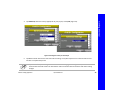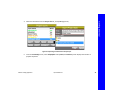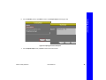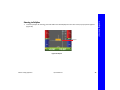
1
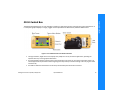
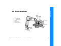
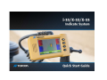
i-33/X-33/X-32 Quick Start Guide Part Number 1003052‐01 Rev A ©Copyright Topcon Positioning Systems, Inc. October, 2013 All contents in this manual are copyrighted by Topcon Positioning Systems, Inc. All rights reserved. Terms and Conditions Thank you for buying this Topcon product. This manual has been prepared to assist you with the care and operation of the product and its use is subject to these Terms and Conditions and those more fully set forth in the Operator’s/User’s Manual. Usage and Safety This product is designed for use by professionals. Always use safety precautions when operating this or any Topcon product. See “Safety Warnings” on page x for details. Copyrights and Trademarks The information in this manual is a copyright of Topcon and is for use only with the product. i‐33 ™, X‐33 ™, X‐32 ™, 3D‐MC, GX‐30, and Topcon are trademarks or registered trademark of Topcon Positioning Systems, Inc. Windows and the Windows CE icon are registered trademarks of Microsoft Corporation. Other product and company names mentioned herein may be trademarks of their respective owners. Disclaimer of Warranty and License Agreement Please see the Operator’s/User’s Manual for detailed information on warranties and the license agreement which may apply to the Product. Except for such warranties and licenses provided with the product, this manual and the product are provided “AS‐IS”. Topcon and its distributors shall not be liable for technical or editorial errors or omissions contained herein; nor for incidental or consequential damages resulting from the furnishing, performance or use of this material or the Product. Use of any computer programs or software supplied by Topcon or downloaded from the Topcon website in connection with the Product implies acceptance of the Terms and Conditions here and in the Operator’s/User’s Manual. Introduction •••••• Getting to know the i-33/X-32/X-33 Systems Topcon’s X‐32™ and X‐33™ systems for excavators are indicate grading systems providing 2D (X‐32) and 3D (X‐33) elevation grade control. The 3D system uses GNSS technology to precisely locate the bucket position (or cutting edge) of the machine in real time anywhere on the construction site. The 2D system uses a compass to achieve similar results. Both systems reduce the need for costly stakeout and survey. Topcon’s i‐33™ system provides similar 3D functionality for dozers and scrapers, and is available in two configurations (single and dual GPS). The Single GPS configuration uses one GPS antenna, and the dual GPS configuration uses two GPS antennas. System Components Table 1 lists the components of the X‐32, X‐33, and i‐33 systems: Table 1. X‐32/X‐33/i‐33 Components Machine Components GX‐30 Control Box Cables Mounting Hardware TS‐i3 Tilt Sensors (X‐32/X‐33 Only) Compass (X‐32 Only) Introduction GNSS Components Radio Antenna MC‐i3 GNSS Receiver GNSS Antenna and Radio P/N: 1003052‐01 1 Introduction GX-30 Control Box The GX‐30 Control Box (Figure 1) is the operator’s interface, as well as the primary control for the system components. It is a computer graphic display in a single, rugged unit that provides three‐dimensional, stakeless GNSS control. Figure 1: Front and Back View of the GX‐30 Control Box • The high‐resolution, bright touch screen display easily adapts to a variety of machine applications, providing the operator with easy‐ to‐view graphical information. • A mounting bracket and one side clamp secure the Control Box in the cab or you can mount system with suction cup. • The clamps provide easy attachment at the beginning of the day and easy removal for storage in the carrying case at the end of the day. One cable is attached in the back and can be easily removed with quick‐disconnect connectors. Getting to know the i‐33/X‐32/X‐33 Systems P/N: 1003052‐01 2 Introduction MC-i3 GNSS Receiver The MC‐i3 GNSS Receiver (Figure 2) attaches to the machine with shock isolated magnetic mounts. It can be easily removed at the end of each day for storage. The MC‐i3 combines Topcon’s GNSS receiver module and a radio module into a single, rugged housing. When used in conjunction with a base transmitter, this combination provides the control box and operator with Real Time Kinematic (RTK) measurements. The control box processes these real time measurements to compute grade and graphical mapping information. Figure 2: MC‐i3 GNSS Receiver Getting to know the i‐33/X‐32/X‐33 Systems P/N: 1003052‐01 3 Introduction PG-S3 GPS Antenna For GNSS indicate applications, the PG‐S3 GPS Antenna (Figure 3) can be affixed to the top of the mounting pole. The rugged antenna is specially designed to perform on earth‐moving equipment. Figure 3: PG‐S3 Antenna With and Without Mount Getting to know the i‐33/X‐32/X‐33 Systems P/N: 1003052‐01 4 Introduction X-32 Machine Configuration Boom Sensor Radio Antenna • • • • • GX‐30 Control Box TS‐i3 Tilt Sensors (x4) Compass Radio Antenna MC‐i3 GNSS Receiver Stick Sensor Compass Body Sensor Bucket Sensor Getting to know the i‐33/X‐32/X‐33 Systems P/N: 1003052‐01 MC-i3 GX-30 5 Body Radio Antenna Boom Stick Introduction Sensor Terminator TS-i3 Tilt Sensors Bucket GX-30 7.5 Amp In-Line Fuse Required MC-i3 CAN Compass Serial Figure 4: X‐32 Components Getting to know the i‐33/X‐32/X‐33 Systems P/N: 1003052‐01 6 Boom Sensor Radio Antenna • • • • • GX‐30 Control Box TS‐i3 Tilt Sensors (x4) Radio Antenna GPS Antennas (x2) MC‐i3 GNSS Receiver Introduction X-33 Machine Configuration GPS Antennas Stick Sensor Body Sensor MC-i3 Bucket Sensor Getting to know the i‐33/X‐32/X‐33 Systems P/N: 1003052‐01 GX-30 7 Introduction TS-i3 Tilt Sensors Main Aux GPS GPS Antenna Antenna Radio Antenna Body Boom Stick Bucket 7.5 Amp In-Line Fuse Required GX-30 MC-i3 CAN Serial External Radio Modem Figure 5: X‐33 Components Getting to know the i‐33/X‐32/X‐33 Systems P/N: 1003052‐01 8 Introduction i-33 Machine Configuration GPS Antennas • GX‐30 Control Box • Radio Antenna • GPS Antennas (Dual GPS Optional) • MC‐i3 GNSS Receiver MC-i3 Radio Antenna GX-30 Getting to know the i‐33/X‐32/X‐33 Systems P/N: 1003052‐01 9 Introduction Main Optional Aux Radio GPS GPS Antenna Antenna Antenna 7.5 Amp In-Line Fuse Required GX-30 MC-i3 CAN Serial External Radio Modem Figure 6: i‐33 Components Getting to know the i‐33/X‐32/X‐33 Systems P/N: 1003052‐01 10 Features & Functions •••••• Component Functions The X‐32, X‐33, and i‐33 components constantly communicate with each other to provide accurate, real‐time measurements. Each component has a specific function, which provides the operator with control, graphical job site displays, or GNSS measurements for quick and easy grading. Topcon Menu Button The Topcon Menu Button is located at the top right corner of the GX‐30 Control Box. When pressed, 3D‐ MC displays a list of four menus: File, Control, Tools, and View (Figure 7). The menus disappear if not used for ten seconds Figure 7: Topcon Logo Menus Features & Functions P/N: 1003052‐01 11 Features & Functions File and Control Menus The File menu (Figure 8) contains all of the functions needed to create new and edit existing 3D‐MC project files. The Control menu contains options for machine setup, blade control, and as‐built functions. To access the File or Control menus, press the Topcon Menu Button and tap either File or Control on the screen. Figure 8: File Menu and Control Menus Component Functions P/N: 1003052‐01 12 With the Tools menu (Figure 9) you can configure the radio, check the machine position, connect to Sitelink3D (OAF option), and perform data logging (OAF option). The View menu lets you change what is displayed on the left and right of the screen of the control box as well as enter authorization codes. To access the Tools or View menus, press the Topcon Menu Button and tap either Tools or View on the screen. Figure 9: Tools and View Menus Component Functions P/N: 1003052‐01 13 Features & Functions Tools and View Menus Features & Functions Elevation Control Key Figure 10: Elevation Control Key Component Functions P/N: 1003052‐01 14 Features & Functions Adjust Elevation ŝƐƉůĂLJƐƚŚĞĞůĞǀĂƟŽŶŽĨ ƚŚĞďůĂĚĞ͛ƐůĞŌĞĚŐĞ͘ ŝƐƉůĂLJƐƚŚĞĞůĞǀĂƟŽŶŽĨ ƚŚĞďůĂĚĞ͛ƐƌŝŐŚƚĞĚŐĞ͘ Sets the ůĞǀĂƟŽŶƐĞƚƉŽŝŶƚ ǀĂůƵĞƚŽnjĞƌŽ͘ ŝƐƉůĂLJƐƚŚĞĐƵƌƌĞŶƚ ĐƵƚͬĮůůŽīƐĞƚ͘ ^ĞƚƐƚŚĞĐƵƌƌĞŶƚĚĞƐŝŐŶƐƵƌĨĂĐĞƚŽ ƚŚĞĐƵƫŶŐĞĚŐĞĞůĞǀĂƟŽŶ͘ Displays the 'W^ŝŶĨŽƌŵĂƟŽŶ ĚŝĂůŽŐďŽdž͘ Figure 11: Adjust Elevation Screen MC‐i3 units with either FH915+ or Digital UHF2 will not have the second GPS info... button. Component Functions P/N: 1003052‐01 15 Getting Started •••••• Creating a Machine Configuration File (X-32/X-33 Only) The following briefly describes creating a machine configuration file and calibrating a bucket for X‐32 and X‐33 systems only. For a detailed procedure, see the 3D‐MC Reference Guide P/N 7010‐0911. Machine Setup 1. 2. 3. 4. 5. 6. On the GX‐30, press the Topcon Menu Button and tap ControlMachine setup in 3D‐MC. Tap New to begin creating a machine configuration file. The Configuration name/type screen appears. Set up the machine name and type, and tap Next (Figure 12). Set up the position and sensor inputs of the machine, and tap Next. Configure the antenna mounting position and heights, and tap Next. Set up the sensors for the frame, stick, dog‐ bone, and bucket, and tap Next. The Excavator Buckets screen appears. Getting Started P/N: 1003052‐01 Figure 12: Machine Configuration 16 Getting Started . Bucket Calibration 1. 2. 3. 4. 5. 6. Tap New to begin creating a new bucket. The Excavator Bucket Setup screen appears (Figure 13). Input the dimensions of the bucket and tap Next. Calibrate the bucket edge and base, and tap Finish. The Excavator Buckets screen appears. Select your bucket, and tap Next. Set up the GPS information. On the Configuration Complete! screen, tap Finish. Your machine configuration file is now finished. Figure 13: Excavator Buckets Creating a Machine Configuration File (X‐32/X‐33 Only) P/N: 1003052‐01 17 You can copy any of the 3D‐MC file types to and from a flash drive. The examples below use the Project Files screen, but any control point, surfaces, alignment, linework, points, or machine configuration file can be copied. 1. Insert a flash drive into the USB slot on the back of the control box, and power on the unit. 2. 3. 4. Press the Topcon Menu Button and tapFileProjects. On the Project Files screen tap Copy. The Copy files screen appears. In the From: drop‐down menu, select F: to 3DMCi folder. Note that the letter of the flash drive may be different (Figure 14 on page 19). Creating a Machine Configuration File (X‐32/X‐33 Only) P/N: 1003052‐01 18 Getting Started Copying Files Getting Started Figure 14: Copying Files From a Flash Drive 5. 6. Select the desired files to copy and tap OK. When the Project Files screen appears, tap OK to return to the main screen. Creating a Machine Configuration File (X‐32/X‐33 Only) P/N: 1003052‐01 19 The blade control function selects the point on the blade that will be the cutting edge. Note that the Automatic best‐fit selection is not active for i‐33 systems. Setting Blade Control You can set the blade control point using either the Section view or the Blade Control menu. To change the blade control point using the Section view, follow the steps below. 1. 2. 3. Press the Topcon Menu Button and tap ViewLeft windowSection. The Section view appears on the left side of the screen. Press and hold the edge of the blade for one second. On the pop‐up menu, tap Move control left or Move control right. The blade control arrow moves accordingly (Figure 15). Blade Edge Figure 15: Setting the Blade Position With Section View Blade Control P/N: 1003052‐01 20 Getting Started Blade Control 1. 2. 3. 4. Getting Started To change the blade control point using the Blade Control screen, follow the steps below. Press the Topcon Menu Button and tap ControlBlade control. Select Control using single point on blade, and press and hold the slider button. Move the slider button left or right to select the point from the side of the blade (Figure 11). Tap OK to apply this point to the machine file. Figure 16: Blade Control Menu For i‐33 systems, the Best‐fit (whole blade) option will appear on the screen, but will not be selectable. Blade Control P/N: 1003052‐01 21 Getting Started Indicate Grading Application Once you have your system set up, most grading operations remain the same. While grading, you can: • • • • • • • copy files change cut/fill offsets change the grade indicator scale check the blade position change radio channels Steer and grade to a polyline change the display units Changing the Cut/Fill Offset The cut/fill offset can be manually adjusted, on the fly, relative to the design surface. After each pass, the cut/fill offset can be updated as necessary while approaching the final design surface. Indicate Grading Application P/N: 1003052‐01 22 The grade indicator acts as an infinitely scrolling grade tape, displaying the amount of cut or fill in regards to the design surface. To view the grade indicator, press the Topcon Menu Button and tap ViewLeft windowGrade indicator (Figure 17). Grade Indicator Figure 17: Grade Indicator Indicate Grading Application P/N: 1003052‐01 23 Getting Started Changing the Grade Indicator Scale Getting Started To change the On‐grade (green zone) or Extents (unit spacing), press and hold the Grade indicator for one second, then tap the desired menu option (Figure 18). • On‐grade – displays the current on‐grade zone • width. Tap to display the numeric pop‐up keyboard to change the on‐grade zone. Extents – displays the current scale for the grade indicator. Tap to display the numeric pop‐up keyboard to change the unit spacing. Figure 18: Changing On‐grade and Extents Indicate Grading Application P/N: 1003052‐01 24 The position check option provides a daily benchmarking tool to verify that the calculated elevation and position are repeatable. 1. 2. To check the position of the blade, press the Topcon Menu Button and tap ToolsPosition check. On the Position Check screen, select the Point (left, middle, or right), and tap Measure (Figure 19); the Measuring dialog box displays. Figure 19: Checking the Blade Position Indicate Grading Application P/N: 1003052‐01 25 Getting Started Checking the Blade Position 4. 5. Getting Started 3. When finished, the Position Check screen displays the point on the job of the selected edge of the blade. Tap Save; the Position Details screen appears (Figure 20). Select the appropriate options from the Layer and Point Description drop‐down lists, and tap OK; the Position Check screen appears. Tap Cancel to return to the main screen. Figure 20: Position Details Screen Indicate Grading Application P/N: 1003052‐01 26 Getting Started Changing Radio Channels If needed, you can use the control box to change the radio channel of Digital UHFII and other types of radio modems. The MC‐i3 GNSS Receiver stores radio settings, including the radio channel. Follow the steps below to set up or change the radio channel settings. 1. 2. Press the Topcon Menu Button, and tap ToolsConfigure Radios. On the GNSS Radio Setup screen, select your radio type and tap Configure (if available) to run the radio setting program (Figure 21). The configuration screen for your board type appears. Figure 21: Configuring Your Radio Channel Indicate Grading Application P/N: 1003052‐01 27 Getting Started It may take anywhere from few seconds to a few minutes to connect to the radio module, and check the current setting. When the current setting is confirmed, the radio’s channel and frequency information displays. 3. On the configuration screen, tap the Channel drop‐down list box and select the desired channel number. The frequency of the channel changes automatically depending on the selected channel (Figure 22). Figure 22: Setting the Channel number Indicate Grading Application P/N: 1003052‐01 28 Tap Advanced, select the country appropriate to your project, and tap OK (Figure 23). Getting Started 4. Figure 23: Setting the Country for the Project 5. Tap Set to activate and save the new radio channel setting. It may take anywhere from a few seconds to a few minutes to complete the process. If you have difficulty connecting to the radio module when changing radio configurations, disconnect the radio antenna cable at the MC‐i3 Box. The base station radio can interfere with the machine radio when making changes. Indicate Grading Application P/N: 1003052‐01 29 Polylines are part of a linework, which are contained in layer files. The polyline represents features or objects such as building pads, curbs, sidewalks, top and toe of slopes, or any boundary on the project. The control box can control a machine to steer and cut to a polyline. You can select three‐dimensional information at each transition point of a polyline to steer the machine to a particular area. Polylines can also represent design elevation to control the cutting edge. Loading a Linework from a Project Layer 1. 2. 3. Press the Topcon Menu Button, and tapFileLayers. Select a layer file from the Project Layers screen, and tap Import. In the Import Project Data screen, select Linework from project file (TP3) and 3DMC folder from the What: and Where: drop‐down lists. Indicate Grading Application P/N: 1003052‐01 30 Getting Started Steering and Grading to Polyline Select the desired file from the Project files list, and tap OK (Figure 24). Getting Started 4. Figure 24: Importing a Linework from a Project Layer 5. From the Linework(s) screen, select All polylines and tap Next; the Summary screen displays the number of polylines imported. Indicate Grading Application P/N: 1003052‐01 31 On the Summary screen, tap Finish to return to the Project Layers screen (Figure 25). Getting Started 6. Figure 25: Importing Linework and Polylines 7. On the Project Layers screen, tap OK to return to the main screen. Indicate Grading Application P/N: 1003052‐01 32 1. To select a polyline for steering, press and hold on the desired polyline on the main screen; a pop‐up menu appears. (Figure 26). Polyline Figure 26: Polyline Indicate Grading Application P/N: 1003052‐01 33 Getting Started Steering to Polyline On the pop‐up menu, tap PolylineSteer to; graphical cross lines display along the selected polyline (Figure 27). Getting Started 2. Figure 27: Selecting and Steering to a Polyline Indicate Grading Application P/N: 1003052‐01 34 4. 5. 6. Getting Started 3. To change the steering indication, press the Topcon Menu Button and tapControlSteer indication; enter the desired changes and tap OK.(Figure 28). To select another polyline, repeat steps 2 and 3. To change the alignment file, press the Topcon Logo Button and tapFileActiveAlignment. The current polyline displays in the list with a check next to it. To choose a new alignment, select it from the list. Figure 28: Changing the Steer Indication Indicate Grading Application P/N: 1003052‐01 35 1. To select a polyline for grading, press and hold on the desired polyline on the main screen; a pop‐up menu appears. 2. Tap PolylineExtend grade; graphical cross lines display along the selected polyline (Figure 29). Figure 29: Grading to Polyline Indicate Grading Application P/N: 1003052‐01 36 Getting Started Grading to Polyline Getting Started Changing the Display Units On the Display Units screen, you can change the type of units displayed on the screen, or update preset units in the files currently being used without affecting grade accuracy. You can choose among the following: • Distances – select either Meters, US survey feet, or International feet • Angles – select either DDº MM’SS”, NDDº MM’SS”, or Gons • Grades – select either Percent (%) or Run : Rise • Stations – select either 100.000, 1+00.000, or 10+0.000 • Volumes – select either Cubic meters or Cubic yards • Coordinates – select either North‐East‐Elev, East‐North‐Elev, or X‐Y‐Z To set the type of units used in the job, press the Topcon Menu Button and tapViewDisplay optionsDisplay units. The Display Units screen appears (Figure 30). Indicate Grading Application P/N: 1003052‐01 Figure 30: Changing the Display Units 37 Getting Started Slope Profiles (X-32/X-33 Only) The following section is a brief description of how to enter slope profiles in 3D‐MCi for X‐32 and X‐33 systems. For a detailed description, see the 3D‐MC Reference Guide P/N 7010‐0911. Known Slope 1. 2. On the GX‐30, press the Topcon Menu Button and tap ToolsKnown Slope. Enter the Grade percentage or the Rise and Run values, and tap OK (Figure 31 on page 39). Known Dual Slope 1. 2. On the GX‐30, press the Topcon Menu Button and tap ToolsKnown Dual Slope. Enter the X/Y Slope percentage or the X/Y Rise and Run values, and tap OK (Figure 32 on page 39). Slope Profiles (X‐32/X‐33 Only) P/N: 1003052‐01 38 Getting Started Figure 31: Setting a Known Slope Figure 32: Setting a Known Dual Slope Measured Slope 1. 2. 3. On the GX‐30, press the Topcon Menu Button and tap ToolsMeasured Slope. Set the bucket teeth on the slope to be measured, and tap OK at the prompt to measure the first point. Move the bucket teeth to another location on the slope, and tap OK at the prompt to measure the second point. Slope Profiles (X‐32/X‐33 Only) P/N: 1003052‐01 39 1. 2. 3. 4. Getting Started Complex Slope On the GX‐30, press the Topcon Menu Button and tap ToolsComplex Slope. Name the slope, and tap Add (Figure 33). Enter the slope element values, and tap OK (Figure 34). Repeat steps 1‐3 to add more slope elements. Figure 33: Add a Complex Slope Figure 34: Enter Slope Elements Normal to Surface To indicate a surface cut/fill that is perpendicular (normal) to the surface model of an excavator, tap ControlElev. ReferenceNormal to surface. Slope Profiles (X‐32/X‐33 Only) P/N: 1003052‐01 40 Getting Started Referencing Zero to Bucket 1. In 3D‐MC, tap the Elevation Control Key. The Adjust Elevation screen appears. 2. Tap Zero to Bucket (Figure 35) The bucket teeth are now used as the height reference for Known, Measured, and Complex Slope profiles. Figure 35: Zero to Bucket Referencing P/N: 1003052‐01 41 Getting Started Reverse Slope Direction To reverse the slope direction, tap ToolsReverse slope direction (Figure 36). Figure 36: Reversed Slope Direction Reverse Slope Direction P/N: 1003052‐01 42